119. Ground Pyrotechnics are designed to give warning of enemy marauders or infiltrating hostile troops, to illuminate the ground in front of entrenched or advancing troops, and for communication by signaling. Pyrotechnic items used in ground operations include tripwire flares, parachute flares, pyrotechnic grenades, and a variety of ground signals.
Trip-Wire Flare Mk 1 Mod 0
120. Trip-Wire Flare Mk 1 Mod 0, Fig. 53, is an alarming device which an approaching enemy unconsciously sets off. It also gives illumination for some 65 seconds. It burns with a bright yellow flame of 75,000 candlepower, resulting in illumination of an area within a radius of approximately 75 feet. The flare is packed in a watertight mailing tube container, which includes the accessories that go with it; namely, 80 feet of wire, two screw eyes, and a belt for attaching the flare to a stake or tree. The flare itself consists of a steel tube 5.5 inches long and 2.5 inches in diameter. Fixed to one end is the firing mechanism, consisting of a pull-type spring to which the trip wires are attached, a primer, and a firing pin. Included in the kit is an instruction sheet outlining the procedure for mounting the flare. When properly mounted, the flare, with its safety pin removed, is fired when the trip wire is pulled. The wire is attached to a plunger with a notched end, which, when pulled, disengages itself from the firing pin. The firing pin, under spring pressure, then strikes the primer which ignites a 0.3-gram charge of black powder. The flash from the black powder ignites the pyrotechnic candle. The candle, on burning, creates sufficient pressure to blow off the closure disc on the flare case, and thus exposes the flame.
Operation
121. Some amount of ingenuity is necessary for the most efficient operation of Trip-Wire Flare Mk 1. Like a booby trap, its concealment
is desirable. The 80 feet of wire can be halved so that two 40-foot lengths can be attached to the plunger, stretching both ways from the flare, and parallel to the enemy lines. The following steps should be taken:
(a) Secure the flare to a tree or stake by means of the belt and belt loop. It should be mounted about three feet from the ground.
(b) Attach the trip wires to a tree or stake just less than 40 feet on either side of the tree or stake to which the flare is attached.
(c) A screw eye is fixed to the tree or stake on which the flare is mounted. This screw eye should be about six inches from the ground, directly beneath the plunger.
(d) The free ends of the trip wire or wires are then passed through the screw eye and secured to the pull ring on the plunger of the firing mechanism. The wire or wires should be affixed so that there is no sag in the 40- or 80-foot length, but not so taut that it will actuate the plunger.
(e) After the wires and flare are installed, set the device by pressing up on the plunger and carefully withdrawing the safety pin.
(f) Release. the upward pressure on the plunger slowly and note its travel downward. This should not be more than 0.25 inch. If, at that point, further downward pressure is felt on the finger holding the plunger, return it to the up position and replace the safety pin. Then slack off on the trip wires. Normally the plunger will not move downward more than 0.125 inch.
(g) If at this point it has been found necessary to replace the safety pin, repeat steps (e) and (f) with caution, each time the safety pin is removed.
(h) After the flare is set, free the plunger from any paint or other substance which may seal it to the wall of the flare. This is done by carefully turning the plunger through a 90-
70
Figure 54.-Trip-Wire Flare M48
71
degree arc without allowing it to travel downward.
Packing
122. Each flare, with its accessories, is packed in a watertight container. Ten such containers are packed in a wood case. Each case contains an instruction sheet for using Trip-Wire Flare Mk 1 Mod 0.
Storage
123. General rules for storing pyrotechnic ammunition as outlined in paragraphs 9 to 12, inclusive, apply to Trip-Wire Flare Mk 1. Although the flare and its container are waterproofed, long periods of exposure to rain or excess moisture may result in malfunctioning. Deteriorated flares should be disposed of as outlined in paragraph 20.
Safety Precautions
124. In mounting Trip-Wire Flare Mk 1, the following safety precautions must be taken:
(a) A steel helmet should be worn while mounting and setting the flare. The head must be kept below and away from the flare as far as possible.
(b) When two trip wires are used, each must be attached to the plunger independent of the other, although both may be passed through the same screw eye.
(c) To prevent self-illumination, the flare should be mounted at least 125 yards in advance of the defense position.
(d) It should be remembered that the plunger of the flare is actuated by a pull of six pounds. The plunger should be freed by turning it 90 degrees, after removing the safety pin.
Flare, Trip, Parachute M48
125. Parachute Trip Flare M48, listed as above, is, in effect, a one-shot mortar fired by a trip wire. It projects an illuminating flare to an altitude of 300 to 500 feet, where a parachute-borne candle ignites when expelled from the shell case. The candle burns for about 20 seconds with a yellow-white light of approximately
110,000 candlepower, and illuminates an area with a radius of 300 yards. The complete flare consists of a base, on which the flare and parachute unit is contained in a steel tube, 2.4 inches inside diameter. In the base of the tube is the propelling charge of 75 grains of propellant powder. Above the propelling charge is a fuze of approximately three seconds' delay. This fuze ignites the expelling charge in the shell as it attains the proper altitude. The expelling charge then ejects the candle and parachute, igniting the candle by means of a second fuze which is threaded through a felt pad that separates the candle from the expelling charge. The entire flare is fired by a trip wire attached to the firing mechanism which is contained in a 0.25-inch pipe mounted on the base parallel to the steel tube containing the flare unit. The firing mechanism consists of a firing pin, actuated by a spring, a primer, an igniter, and a relay charge. See Fig. 54. The flare is held in safe condition by a double safety: a cotter pin which holds the pull ring in place and a safety screw. The flare may be fired either by a four-to six-pound pull on the trip wires or by 20 to 30 pounds' pressure on a pressure cap. The flare is hidden by burying it so that the top of the shell is three inches below the ground.
Operation
126. The proper use of Parachute Trip Flare M48 requires the following steps:
(a) The entire flare should be placed in a hole so that the top of the shell is approximately three inches below grade. Arrange the cord on the safety cotter pin so that it will not be buried.
(b) The earth should be tamped down on top of the case.
(c) The trip wire or wires should be attached to a tree or stake in the direction or directions parallel to the enemy lines, or nearly so, and hidden so well as ground conditions permit.
(d) Attach the trip wire or wires to the pull ring of the firing mechanism.
(e) Straighten the safety cotter pin so that it may be withdrawn with a steady pull on the cord, and remove the safety screw.
(f) Test the safety cotter pin for binding.
72
Figure 55.-Trip Wire Flare M49
73
Should it bind when the safety screw has been removed, the trip wire may be too tight, or the fuze may be defective. In either case, replace the safety screw before correcting the defect.
(g) When the safety cotter pin moves freely, leave it in place and cover the flare with loose earth, camouflaging if necessary. Then withdraw the safety cotter pin by drawing gently on the cord.
(h) When leaving the flare set, care must be taken not to step on the pressure cap at the top of the firing mechanism, nor to contact the trip wire.
(i) Record the location of the flare.
Packing
127. Parachute Trip Flare M48 is packed in an individual carton, with one firing device and the required length of suitably colored trip wire. Four such cartons are shipped in a wood box. The housing of the flare is painted and marked in black type, indicating the name of the flare, the lot number, and the date of loading.
Storage
128. General rules for storing pyrotechnic ammunition, as outlined in paragraphs 9 to 12, inclusive, apply to Parachute Trip Flare M48. Deteriorated flares should be disposed of as outlined in paragraph 17.
Safety Precautions
129. In addition to the steps taken in paragraph 126, covering the operation of Parachute Trip Flare M48, the following precautions should be taken:
(a) The flare should be planted so that it will not endanger friendly personnel, and so that the illumination of 300-yard radius will not expose defense positions.
(b) The housing of the flare should be carefully inspected for tight joints before planting. The flare should not be planted in swampy or wet ground so that moisture seeping into the flare housing will cause malfunctioning.
Flare, Trip, M49
130. Trip Flare M49, designated as above, resembles a hand grenade in size and shape, but is subject to instantaneous ignition, instead of delayed action as are hand grenades. It is used as a warning and illuminating signal to detect or combat marauding or infiltrating enemy troops. The flare consists of a cylindrical body of laminated paper, 2.5 inches in diameter and 3.8 inches long, closed at both ends by metal caps. The percussion cap, striker and safety lever, and pin protrude from the head, the safety lever extending around and down the side of the body to the trigger. See Fig. 55. The flare is mounted on a stake, post, or tree by means of a hold plate and anchor clip in which three keyhole slots fit over nail heads on the object to which it is attached. When the safety pin is pulled with the safety lever cocked in safety position by the spring loaded trigger, the trigger must be in the vertical position. The flare is fired when the trigger is thrown out of the vertical position, either by a pull on the trip wire sending it one way, or a cutting of the wire allowing the spring to go the other way, releasing the safety lever. The flare burns with approximately 40,000 candlepower.
Operation
131. Trip Flare M49 is mounted on a stake, post, or tree, to the right of the field or area to be illuminated, when looking toward the enemy. It is mounted between 15 and 18 inches from the ground by placing three nails in the post, stake, or tree, and leaving the nail heads extended so that they will fit into the keyhole slots in the mounting plate. Then take the following steps:
(a) Attach the trip wire to a rigid object approximately 40 feet to the right and 15 to 18 inches above ground when facing the flare.
(b) Loosen the thumb nut on the trigger. Press the safety lever on the fuze against the body of the flare and rotate the trigger counterclockwise against the spring, until the thumb nut is down at six o'clock and the finger at the other end of the trigger restrains the fuze lever.
74
Figure 56.-Hand Illuminating Grenade Mk 1
(c) Pull the trip wire until it does not sag, and wrap it once around the thumb nut. Then tighten the thumb nut. At this point the trip wire should not sag and the trigger should be vertical. Have the fuze lever restrained by its upper end, so that it will continue to hold the lever after the safety pin is withdrawn.
(d) Holding the safety lever with one hand, carefully withdraw the safety pin from the fuze, making certain that the trigger will not turn and fire the flare.
(e) Should it be necessary to remove the flare, reverse the steps above.
Packing
132. Trip Flare M49 is packed in wood boxes containing 16 flares, each with three nails and a 45-foot length of olive drab colored trip wire. Each flare is marked to indicate the type and model, lot number, manufacturer's initials, and date loaded.
75
Storage
133. General rules for the storage of pyrotechnics as outlined in paragraphs 9 to 12, inclusive, apply to Trip Flare M49.
Safety Precautions
134. In addition to the operating instructions in paragraph 131 above, the following safety precautions should be taken when using or setting Trip Flare M49:
(a) In regular installations, the safety pin of the fuze is removed only after the flare is in place and adjusted so that the trigger restrains the safety lever.
(b) When used as a hand grenade, the pin may be removed only while the safety lever is held restrained by the throwing hand, and care must be taken to keep the lever restrained until the flare is thrown.
(c) The incendiary characteristics of Trip Flare M49 must be continuously borne in mind.
Hand Illuminating Grenade Mk 1
135. Hand Illuminating Grenade Mk 1 is used for illuminating areas in night operations. It is similar in size and weight to the fragmentation hand grenade, and may be fired by hand launching or throwing, or by rifle or carbine, provided the small arms are equipped with Adapter, Grenade Projection, Ml. The hand illuminating grenade burns for 25 seconds with approximately 55,000 candlepower. It consists of two steel cups joined together by force fit and sealed with Petman Cement to provide water-proofing.
The upper half of the grenade body contains a fuze of the Bouchon Type (see Fig. 56) , which is similar in action to that used in the fragmentation hand grenade. A safety lever is held restrained in safety position by a safety pin, the pin being removed just prior to launching and while the lever is held firmly against the side of the body of the grenade. The body of the grenade is 4.3 inches long and has a maximum diameter of 2.1 inches. The lower half contains the illuminating compound and a charge of black powder, which is ignited by the primer flash. On release of the safety lever the delay unit is ignited, and after a delay of seven seconds the grenade body is blown apart and the pyrotechnic is ignited.
Hand Operation
136. To launch Hand Illuminating Grenade Mk 1 by hand, hold it firmly in the throwing hand, with the safety lever firm against the side of the grenade body. When ready to throw, withdraw the safety pin with the other hand. Still holding the safety lever firm against the side of the grenade body, draw the throwing arm back and then throw the grenade. The safety lever must not be released until the grenade leaves the throwing hand.
Rifle Launching
137. When launching Hand Illuminating Grenade Mk 1 from a rifle or carbine, care must be taken to use the proper rifle or carbine and the prescribed combination of launcher and cartridge. The following combinations may be used:
RIFLE OR CARBINE
GRENADE LAUNCHER
CARTRIDGE
Rifle, U. S., Cal. 30, M 1903 and M 1903A3
Launcher M1
Cartridge, Rifle Grenade, Cal. 30, M3.
Rifle, U. S., Cal. 30, M 1917
Launcher M2
Cartridge, Rifle Grenade, Cal. 30, M3.
Rifle, U. S., Cal. 30, M1
Launcher M7
Cartridge, Rifle Grenade, Cal. 30, M3.
Carbine, Cal. 30, M1, M1A1, or M1A2
Launcher M8
Cartridge, Grenade Carbine, Cal. 30, M6.
76
Figure 57.-Adapter, Launcher, and Cartridge for use with Hand Illuminating Grenade Mk 1 Mod 0
In launching the grenade by rifle or carbine, take the following steps:
(a) Place the grenade in the adapter by inserting the safety lever into the arming cup and forcing the joint bead of the grenade between the claws of the adapter, Fig. 57.
(b) Place the adapter, with grenade, on the launcher and position it in accordance with the desired range; see range table.
(c) Rotate the adapter on the launcher so that the safety lever is down or to one side of the sight.
(d) Open the bolt and insert the cartridge in the magazine, taking care that it is the proper cartridge for the rifle or carbine to be used.
(e) Close the bolt and aim the rifle or carbine at the target; then elevate the barrel to` an angle of 45 degrees and fire.
(f) It is recommended that the butt of the rifle or grenade be rested on the ground or a suitable buttress. Do not fire the rifle from the shoulder when in the prone position, or in other positions that do not permit the body to move and absorb the recoil.
(g) Varying range may be obtained by using a positioning clip on the launcher, or on the rifle or carbine when either of the latter is held at varying elevation. The following table may be used for reference:
RANGE IN YARDS
ENGAGEMENT ON LAUNCHER
ELEVATION OF BARREL
90
5 rings show
45 degrees
100
4 rings show
45 degrees
115
3 rings show
45 degrees
140
2 rings show
45 degrees
160
1 ring shows
45 degrees
285
0 ring shows
45 degrees
(h) When firing without using the positioning clip, the following table may be used as a guide:
77
RANGE IN YARDS
ELEVATION OF BARREL
GRENADE POSITION ON BURSTING
205
15 degrees
Ground
220
20 degrees
Ground
240
25 degrees
Ground
260
30 degrees
Ground
280
35 degrees
10 feet altitude
285
40 degrees
10 feet altitude
280
45 degrees
20 feet altitude
240
50 degrees
25 feet altitude
215
55 degrees
50 feet altitude
200
60 degrees
75 feet altitude
160
65 degrees
100 feet altitude
115
70 degrees
125 feet altitude
Both the tables above are computed for use with Rifle, U. S. Cal. 30, M1903 only. At ranges of less than 160 yards the use of the positioning clip is recommended, so that the grenade will burst on or near the ground.
Packing
138. Hand Illuminating Grenade Mk 1 is packed in an individual bag of laminated cellophane, heat sealed at both ends so as to be waterproof. Each such package is then packed in a mailing tube container. Twenty-five such containers are shipped in a wood box.
Storage
139. General rules for storing pyrotechnic ammunition as outlined in paragraphs 9 to 12, inclusive, apply to Hand Illuminating Grenade Mk 1. These grenades must be protected from excess moisture and should not be subjected to direct rays of the sun. Faulty or deteriorated grenades should be disposed of as in paragraph 17.
Safety Precautions
140. When using Hand Illuminating Grenade Mk 1 on soggy or swamp land, it may embed itself and result in little, if any, illumination. This is a physical limitation of the item and should be borne in mind. Other precautions to be taken with it are as follows:
(a) As the grenade bursts with considerable force, it must be fired so that it explodes more
than ten feet from the nearest friendly personnel.
(b) The pyrotechnic candle burns with a hot flame and will ignite dry leaves or straw.
(c) Once the grenade has been inserted in the adapter, it must not be removed without first re-inserting the safety cotter pin.
(d) When hand launched, the grenade must be thrown immediately after the safety cotter pin is removed.
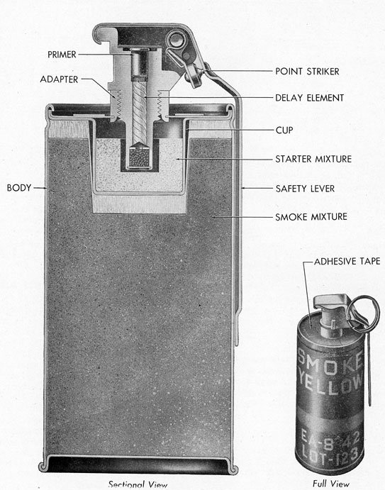
Grenade, Smoke, White (HC) AN-M8
141. White Smoke Grenade (HC) AN-M8, Fig. 58, designated as above, is used for marking, signaling or concealing details in tactical operations on the ground. It is launched by hand, and two seconds after launching emits smoke which reaches maximum output in three seconds and continues for approximately 2.5 minutes. The grenade is a cylindrical container six inches long and 2.5 inches in diameter. The fuze, with a safety lever and its safety pin, protrudes 0.75 inch from the head end. It is assembled complete as Fuze, Igniting, Grenade M200A1, which is similar in appearance to a Bouchon firing mechanism as used on other pyrotechnic ammunition. A new fuze, designated as M201, is currently under procurement, but no attempt must be made to refuze those grenades already issued.
Operation
142. To operate White Smoke Grenade (HC) AN-M8, hold it in the throwing hand with the
78
Figure 58.-Smoke Grenade (HC) ANM8 and M18
79
safety lever pressed firmly against the side of the case. Withdraw the safety pin with the other hand, draw the throwing arm back, and throw. Do not release the safety lever until the grenade leaves the throwing hand.
Packing
143. White Smoke Grenade (HC) ANM8 is packed in an individual moisture-resistant fiber container, and 25 such containers are shipped in a wood box. The grenade is painted gray and is marked in yellow on one band, showing "HC" which is the type of smoke, and the word "SMOKE" to indicate the effect.
Stowage
144. General rules for the storage of pyrotechnic ammunition as outlined in paragraphs 9 to 12, inclusive, apply to White Smoke Grenade (HC) ANM8. In stowage aboard ship, however, this item should be stowed in cool and dry locations above decks, because of the difficulty in combating the smoke in case of fire.
Safety Precautions
145. In using White Smoke Grenade (HC) ANM8, the following safety measures should be taken:
(a) The safety lever must not be released until actual ignition is desired. The delay after the release of the safety lever is only two seconds.
(b) The grenade may be thrown with a full arm swing, or it may be placed on the ground. It should never be put within five feet of other inflammable material.
(c) All personnel should remain more than five feet from the grenade as it ignites and emits its smoke. The smoke, though harmless, is evolved with considerable force and with a tendency to give off hot particles of residue.
Grenade, Smoke, Colored, M16
146. Colored Smoke Grenade M16, designated as above, is similar to White Smoke Grenade (HC) ANM8, except that it emits colored smoke. It is available in RED, YELLOW, GREEN or VIOLET colors, and the color should be
requested when ordering. Instructions for use of this item are the same as those given in paragraphs 141 to 145, inclusive. Only a small quantity of this signal is available.
Grenade, Smoke, Colored, M18
147. Colored Smoke Grenade M18, designated as above, is similar to Colored Smoke Hand Grenade M16 in paragraph 146, except that the burning time of grenade M18 is reduced to one minute. It thus produces a larger and denser cloud of smoke than the Grenade M16. Grenade M18 is designed to supersede Grenade M16 eventually. Instructions for use are the same as those for White Smoke Hand Grenade (HC) ANM8, as described in paragraphs 141 to 145, inclusive.
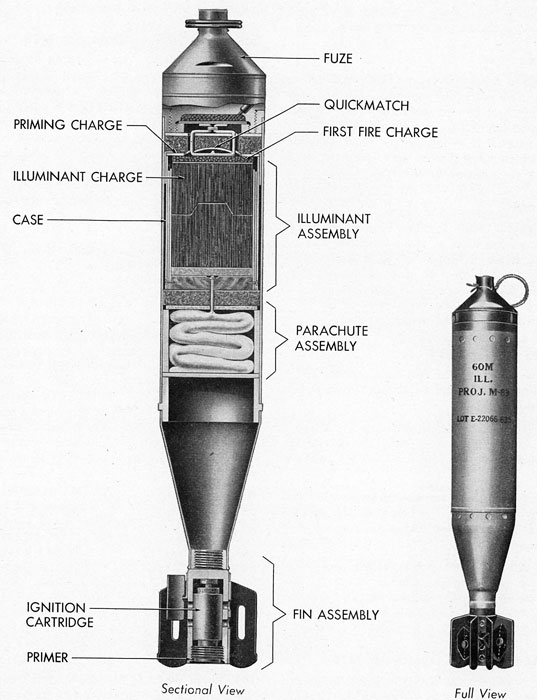
Shell, Illuminating, 60-mm, M83, With Fuze, Time (Fixed) M65, (Army Ordnance)
148. The 60-mm Illuminating Shell M83, designated as above, is used by ground troops to illuminate objectives beyond the range of other pyrotechnic ammunition. It is fired from a 60-mm mortar and furnishes 145,000 candlepower from a parachute-borne pyrotechnic candle. The shell is 14.28 inches in length, 2.33 inches in diameter, weighs 3.7 pounds, and has four fins spaced about a hollow tail stem which contains the initial ignition charge and primer. Nested in the four fins are pellets of propelling increments in bundles of square powder flake. See Fig. 59. The escape of gases generated by the initiating and propelling charges is provided by 16 vent holes. The Fixed Time Fuze M65 in the nose of the shell functions approximately 14 seconds after the shell leaves the mortar. It expels the candle and parachute, igniting the candle at the same time. The time fuze is held in safety position by a pull-ring safety pin, which is withdrawn immediately before loading it in the muzzle of the mortar.
Operation
149. When ready to fire the 60-mm Illuminating Shell M83, the safety pin is pulled and the shell dropped fins first down the muzzle of the mortar. The loader must withdraw his hands and immediately step back, as the shell slides
80
Figure 59.-Illuminating Shell M83
81
down the mortar barrel by gravity and strikes the firing pin to ignite the propelling charge. At the instant of firing, a setback element in the fuze ignites the black powder time train in the nose of the shell. This burns for 14 seconds and then ignites the expelling charge, dividing the shell and ejecting and igniting the pyrotechnic candle suspended on its parachute. The candle burns for 25 seconds and descends at a rate of about ten feet per second. The ballistic properties of the illuminating shell are markedly different from those of the standard 60-mm service shell. The illuminating shell will thus not illuminate the target of the high explosive shell used in the same mortar at the same elevation.
Packing
150. 60-mm Illuminating Shell M83 is packed in individual fiber containers. Six containers are packed in one outer container, and three outer containers are shipped together, totaling 18 rounds per bundle. Each shell is painted gray and is marked in black to indicate the type and model, the mortar from which it is to be fired, the filler, and the lot number. The fuze flange on each shell is stamped to indicate the type and model, the manufacturer's symbol, the lot number, and the date of loading.
Storage
151. General rules for the storage of pyrotechnic ammunition as given in paragraphs 9
to 12, inclusive, apply to 60-mm Illuminating Shell M83. Misfired or deteriorated shells should be disposed of as detailed in paragraph 17.
Safety Precautions
152. In firing 60-mm Illuminating Shell M83, the following safety measures must be taken:
(a) The safety pin in the fuze is to be removed only as the shell is loaded into the mortar and at no other time. Should the round misfire and the shell be removed from the mortar, the safety pin must be replaced immediately.
(b) The shear wire just beneath the safety pin must not be disturbed. This fine wire passes through the fuze and has its ends twisted on the outside. If the wire is broken or missing, the round should be discarded.
(c) Not more than the four propelling increments are to be used under any circumstances.
Signals, Ground (Army Ordnance)
153. The variety of ground signals used in Naval pyrotechnics produce signal stars (parachute borne), clusters of five stars which fall free, and other special effects. Each signal consists of a cylindrical signal case six inches long and 1.6 inches in diameter, equipped with a tail and fins to stabilize it in flight. They
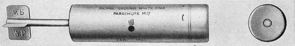
Figure 60.-Signal, Ground, White Star, Parachute, M17
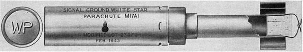
Figure 61.-Signal, Ground, White Star, Parachute, M17A1
82
are fired from a ground signal projector or a rifle grenade launcher, and the proper firing mechanism must be used with each signal. The signal is projected to about 600 feet altitude, where the expelling charge ignites and ejects the signal contained in the cylindrical case. A time fuze, with a delay of six seconds, is provided so that the case may attain the altitude as the expelling charge ignites. Signals are of two types, one for use with Ground Signal Projectors M3 and M4, and one for use with service rifles or carbines equipped with the proper grenade launchers. The firing mechanism for each type will be found following the description of the type.
Signal, Ground, Series M17 to M22
154. Ground Signal M17 to M22, inclusive, is shown in Figs. 60 and 61. Each signal is for use with Ground Signal Projectors M3 and M4. The signal is nine inches long, including the tail assembly on which the initials indicating the content of the six-inch body are embossed. The expelling charge within the body ignites and ejects the pyrotechnic approximately six seconds after it is fired. The signal list and marking for the series is as follows:
(a) Ground Signal M17 produces a parachute-borne WHITE star of 20,000 candlepower for 20 to 30 seconds. The tail vanes are painted WHITE and embossed with the letters "WP", indicating a white star parachute load.
(b) Ground Signal M18 produces five freely falling WHITE stars in cluster, each star of 18,000 candlepower. The cluster burns for five to seven seconds. The tail vanes are painted WHITE and are embossed with the letters "WS", indicating a white star cluster loading.
(c) Ground Signal M19 produces a parachute-borne GREEN star of 5,000 candlepower which burns for 20 to 30 seconds. The tail is painted GREEN and is embossed with the letters "GP", indicating a green star parachute load.
(d) Ground Signal M20 produces five freely falling GREEN stars in cluster, each star burning for five to seven seconds with 7,000 candlepower. The tail is painted GREEN and embossed with the letters "GS", to indicate a GREEN star cluster loading.
(e) Ground Signal M21 produces a parachute-borne AMBER star of 4,000 candlepower for 20 to 30 seconds. The tail is painted YELLOW and embossed with the letters "AP", indicating an AMBER parachute load.
(f) Ground Signal M22 produces five free-falling AMBER stars in cluster, each star burning for five to seven seconds with 2,000 candlepower. The tail is painted YELLOW and embossed with the letters "AS", to indicate an AMBER star cluster load.
Projector, Signal, Ground, M3 and M4
155. Ground Signal Projectors M3 and M4, resemble small mortars in that they consist of open-end tubes, with closing caps at the opposite ends that hold a firing pin which ignites the primer of the ground signal when the mortar is struck against the ground. The signal is inverted and loaded into the muzzle of the projector. Leaving the projector tail first, the signal reverses itself after attaining about 100 feet altitude. It then proceeds nose first until it reaches an altitude of 600 feet, where the expelling charge ejects and ignites the contents of the signal body.
Signal, Ground, Series M17A1 to M22A1 and Series M17A1B2 to M22A1B2, Inclusive
156. Ground Signals of Series M17A1 to M22A1 and of Series M17A1B2 to M22A1B2, inclusive, are respectively designed to produce the same signals as those of Series M17 to M22, inclusive. However, they are for use with rifles or carbines equipped with appropriate grenade launchers; so the proper firing device must be used. Both the series of signals are identical, except that those marked with the last two letters B2 are of steel construction. Both these series of signals are 10.4 inches long, including the tail assemblies, and the hollow stem supporting the tail is of larger diameter than the M17 to M22 series. These signals, when launched with the proper devices, rise nose first to the required altitude, instead of starting tail first and reversing at 100 feet, as is the case with series M17 to M22. They are identified as to type and color by the same code as series M17 to M22, but the paint and embossed
83
lettering are on the head of each signal instead of on the tail vanes. See Fig. 61.
Operation With Rifle or Carbine
157. Current models of Ground Signals M17A1 to M22A1 and M17A1B2 to M22A1B2 are for use with service rifles or carbines equipped with the appropriate model grenade launcher. Early lots of the above signals contained in the tail a special cartridge known as CARTRIDGE, RIFLE GRENADE, CAL. 30, M3 and are for use with RIFLE, U. S. M1917, M1903 and Ml. No attempt should be made to fire the above signals from CARBINE CAL. 30, M1 or M1A1, unless the Cartridge M3 is removed from the tail and replaced with CARTRIDGE, CARBINE, GRENADE, CAL. 30, M6. This is accomplished by removing the cork and clip from the tail of the signal and substituting the cartridge M6 for the original Cartridge M3. In more recent lots the signals are packed in assortment. The assortment includes 48 signals in a wood box, which also contains 50 Cartridges M3 for use with the Rifle M1917, M1903 or Ml, and 50 Carbine Grenade Cartridges M6, for use with Carbines M1 and M1A1. When the special cartridge is fired, it ignites the propelling charge in the signal, which is reduced to compensate for the cartridge charge. The combined charge in the cartridge and signal then projects the signal head first to the required altitude.
With the proper cartridge and grenade launcher the following steps should be taken to fire Ground Signals M17A1 to M22A1 and their counterparts of series M17A1B2 to M22A1B2:
(a) Unseal the fiber container and examine the signal to see that the case is not dented and that the tail is straight and attached firmly to the case.
(b) Remove the cork and clip from the tail and place the signal on the launcher.
(c) If the signal is of the earlier lots, remove the cartridge from the cork assembly and load the rifle. If it is from the newer lot, use the appropriate cartridge, which is separately packed.
Storage
158. General rules for the storage of pyrotechnic ammunition detailed in paragraphs 9
to 12, inclusive, apply to ground signals. Faulty Dr deteriorated signals should be disposed of as detailed in paragraph 17.
Safety Precautions
159. The use of the proper firing mechanism for firing ground signals cannot be too fully stressed. The following facts must be remembered:
(a) Use only CARTRIDGE, RIFLE, CAL. 30, M3, when firing with RIFLE, U. S., CAL. 30, M1917, M1903 or Ml.
(b) Use only CARTRIDGE, GRENADE, CARBINE, CAL. 30, M6, when firing with CARBINE, CAL. 30, M1 or M1A1.
(c) In handling signals, the primers should be protected against sharp blows or from contact with sharp instruments which might cause them to fire.
(d) Discard signals with dented or cracked cases, and with bent or deformed fins and tail supports.
(e) When firing, care must be taken to keep all personnel clear of the muzzle of the projector, rifle, or carbine and below the level of the signal when it is placed on the launcher. Care must also be taken to aim the signal so that it, or its parts, will not fall on friendly personnel or ammunition stores. Where practicable, some measure of cover should be taken to avoid falling signal cases.
Pistol Rocket Signal Mk 1 Mod 2
160. Pistol Rocket Signal Mk 1 Mod 2 is similar in construction to Pistol Rocket Signal Mk 1, Comet, as described under Submarine Pyrotechnics in paragraph 95. Signal Mk 1 Mod 2 produces a chameleon signal consisting of three parachute-borne stars which burn successively in three colors. Each star burns for approximately seven seconds before the next color ignites, resulting in a total burning time for the signal of 21 seconds. The signal is fired from Pyrotechnic Pistol AN-M8, or Submarine Rocket Pistol Mk 1, full instructions for which will be found in paragraphs 101 to 105, in the section on Submarine Pyrotechnics. Fig. 62 shows a cross section of Pistol Rocket Signal Mk 1 Mod 2.
84
Figure 62.-Pistol Rocket Signal Mk 1
85
Figure 63.-Pistol Rocket Signal Mk 2
86
Pistol Rocket Signal Mk 2 Mod 1 (Smoke)
161. Pistol Rocket Signal Mk 2 Mod 1, Fig. 63 is a smoke signal used for identification between ground troops and air forces. It is similar in construction and operation to Pistol Rocket Signal Mk 1 Mod 2 above, except that it produces a parachute-borne smoke signal
instead of the chameleon signal of the Signal Mk 1 Mod 2. Instructions for firing, and the details of storage, packing, and safety measures will be found in the section on Submarine Pyrotechnics in paragraphs 95, and 101 to 105, covering Pistol Rocket Signal Mk 1, Comet, Pyrotechnic Pistol ANM8, and the Submarine Rocket Pistol Mk 1.
Figure 64.-Snowflake Rocket Flare and Projector (British)
87
Chapter 8 MERCHANT SHIP PYROTECHNICS
Description
162. Merchant Ship Pyrotechnics include snowflake rocket flares, marine-type rockets, and pistol rocket signals. Descriptions of the items and instructions for use, details of packing, and safety precautions for each are given in the following paragraphs.
Snowflake Rocket Flare
163. Snowflake Rocket Flares, Fig. 64, are of British design formerly furnished for distribution to U. S. merchant ships to provide illumination for the location of submarines at night. No distribution is being made at present. Each flare furnishes some 300,000 candlepower for approximately 65 seconds at an altitude of 1200 feet, where the flare ignition takes place. The burning flare descends with parachute suspension. The flare is projected from a special projector which is fired either electrically or by percussion. The rocket consists of a tube, 36 inches long and 3.3 inches in diameter. It weighs approximately nine pounds and contains the illuminating element in the head and a propelling charge and stabilizing fins at the base. A canvas skirt extends from the head, part way down the tube. It protects the flare and the projector, when the flare is placed in it, from rain or spray. The skirt is pulled over the outside of the projector, when loading. The propelling charge is of black powder, and the illuminating element is a star of the usual type. After the rocket is fired from the projector, it rises for about six seconds before the expelling charge ejects the star and its supporting parachute. The burning star descends at the rate of approximately 20 feet per second.
Operation
164. Snowflake rocket flare is carried loaded in the special projector provided for it. This projector, weighing 35 pounds, is a tube, fitted with a breech-loading device into which a special cartridge is loaded to ignite the rocket-propelling
charge. The tube is fitted into a base plate which is secured to the deck at an angle, to insure a trajectory clear of the ship. The firing angle also prevents the tube and fin assembly of the rocket from falling back on deck when the star and parachute are expelled. The rocket should be fired into the wind, and on most ships two projectors are loaded, so that the one to windward may be used. In order to fire the snowflake rocket flare, a cartridge is placed in the breech of the projector and the flare itself is slid down the tube from the muzzle. The canvas skirt is draped over the muzzle to keep out rain or spray until the actual firing of the projector. At the command to fire, a pull on the lanyard releases a cocked firing pin and fires the special cartridge in the breech. This ignites the black powder rocket, which raises the flare to 1200 feet, where the star and parachute are ejected and ignited by the expelling charge. The following maintenance provisions should be followed:
(a) The Snowflake Rocket Flare should be wiped along its tube with an oily rag, to insure a free fit into the projector tube.
(b) When left in the projector tube, the rocket flare should be raised and lowered in the tube each day until it is fired.
(c) Alight application of Cooper's or similar grease is recommended on the rocket, so that it will not stick in the projector and so that it will repel rain or spray.
(d) The adhesive tape on the rocket head should be kept waterproofed by painting if necessary, and the canvas skirt may also be painted for waterproofing, particularly at its joint on the rocket head.
(e) The special cartridge in the projector should be changed daily to insure positive firing.
(f) Spare snowflake rocket flares should be inspected to make sure that the tape seal at the base is not pierced. If pierced, it should be repaired by gluing on a thin paper patch.
88
Figure 65.-Rocket, White, Marine Type, Mk 1 Mod 0
89
Packing
165. Snowflake rocket flares are packed in wood boxes containing six flares each. It has often been found necessary to straighten fins which have become slightly damaged or bent in transit, or in removing them from the original box. This may be done by tapping the fins back into place. The special percussion cartridges used with the projector are packed in metal cans of ten cartridges.
Stowage
166. General rules for the stowage of pyrotechnic ammunition as detailed in paragraphs 9 to 12, inclusive, apply to snowflake rocket flares. Defective or deteriorated flares should be disposed of as stated in paragraph 17.
Safety Precautions
167. The following precautions should always be borne in mind when handling or operating the projector or snowflake rocket flares:
(a) Snowflake rocket flares always head upwind on firing. For this reason the windward projector should be used, if two are aboard the ship.
(b) Rockets which have been exposed to weather over long periods should be replaced.
(c) The firing lock of the projectors loaded with snowflake rocket flares should be left uncocked until ready for firing.
(d) Rockets of the snowflake type have been known to ignite prematurely. The operator should stand six to eight feet from the projector when firing, and other personnel in the immediate vicinity should take reasonable cover.
(e) Firing lanyards should be led through tubes and fitted with guards to prevent accidental firing of the projector, by tripping over the lanyard.
(f) Care must be taken that the cartridges do not get damp. They should be changed daily, and the retrieved cartridges should be wiped dry before being stowed away.
Marine Type White Rocket Mk 1 Mod 0
168. Marine Type White Rocket Mk 1 Mod 0, Fig. 65, is used for emergency signaling purposes
by merchant ships. It is a standard shower rocket and weighs two pounds. It is fired by a quickmatch when the rocket is mounted on a stave. When it rises to a height of about 250 feet, the shower of approximately 20 white pellets appears in a burst. The burning time of the shower is approximately five seconds. The rocket body is 12 inches long and 1.5 inches in diameter. Attached to the side of the body is a socket, four inches long, which takes the rocket stave, one of which is included in the package containing the rocket. This stave fits snugly into the socket and is 48 inches long. The base of the rocket is sealed with a paper sealing disc, which covers the end of the quickmatch.
Operation
169. To fire Marine Type White Rocket Mk 1 Mod 0, place the stave in the socket and then place the assembly in a trough inclined at an angle of 80 degrees. The paper sealing disc at the base of the rocket body is then pierced and a length of the quickmatch is exposed. The rocket is fired by igniting the quickmatch.
Packing
170. Marine Type White Rockets are packaged to include the wood stave which supports them in the inclined position for firing. They are shipped in containers of 18 units.
Stowage
171. General rules for the stowage of pyrotechnic ammunition as detailed in paragraphs 9 to 12, inclusive, apply to Marine Type White Rockets Mk 1 Mod 0. In stowage it is essential that the item be kept dry and that the paper sealing disc at the base of the body is not punctured.
Safety Precautions
172. When igniting the quickmatch, it is essential that the face be kept above and away from the base of the rocket. It is also important to have the stave securely positioned in the inclined trough. Rockets left in firing position for some time should be covered by day to protect them from direct sun rays.
90
Figure 66.-Pyrotechnic Outfit Mk 2 Mod 0
Pistol Rocket Signal Mk 3 Mod 0
173. Pistol Rocket Signal Mk 3 Mod 0, Fig. 66, is a shower signal designed to supersede Marine Type White Rocket Mk 1 Mod 0. It may be fired from Pyrotechnic Pistol ANM8 or Submarine Rocket Pistol Mk 1 Mod 0. The signal is similar in appearance and construction to Pistol Rocket Signal Mk 1, Comet. When fired, Pistol Rocket Signal Mk 3 Mod 0 rises to a height of 600 feet and in bursting expels approximately 60 white pyrotechnic pellets in shower.
Operation
174. Details for loading and firing pistol rocket signals will be found in the section on Submarine Pyrotechnics in paragraphs 101 to 105, covering Pyrotechnic Pistol ANM8 and Submarine Rocket Pistol Mk 1 Mod 0.
Packing
175. Pistol Rocket Signal Mk 3 Mod 0 will be issued in kit form as described in paragraph
176. Each kit contains two Pyrotechnic Pistols ANM8 and 12 signals.
NOTE: This signal is not to be confused with Pistol Rocket Signal Mk 1 Mod 3, which is also a shower signal but has two separate bursts with a delay of five seconds between bursts. This signal is not being issued at present and is not available. Signal Mk 3 Mod 0 produces a single burst.
Pyrotechnic Outfit Mk 2 Mod 0
176. Pyrotechnic Outfit Mk 2 Mod 0 is now available. The outfit and contents are shown in Fig. 66.
91
Chapter 9 MISCELLANEOUS PYROTECHNICS
Figure 67.-High-Altitude Parachute Flare
and Mortar
Description
177. Several pyrotechnic items are on the procurement list which do not fall into any of the foregoing classifications of ships pyrotechnics, submarine pyrotechnics, etc. These include such items as high-altitude flares, mortars, salutes, and target rocket flares, which will be described hereafter as miscellaneous pyrotechnics.
High-Altitude Parachute Flare
178. The high-altitude parachute flare, Fig. 67, is used primarily to illuminate seaplane landing areas at night, so that incoming seaplanes can alight on the water within the limits of marked channels. It is also used to locate island bases when low ceilings prevent proper visibility from normal flying levels. The flare is fired from a mortar, which will be described under operational paragraph 179. The complete flare consists of a steel tube, closed at one end by a copper cup welded to it. The tube is 10.75 inches long and 2.5 inches in diameter. In the tube are the pyrotechnic candle, of 85,000 candlepower and one minute burning time, a cloth parachute, and the expelling charge. The copper cup contains the propelling charge, a mixture of 25 grams of smokeless powder and black powder, and the primer and fuze assembly. The fuze assembly delays the ignition of the expelling charge until the flare reaches an altitude of 1,000 feet by the pressure of the propelling charge.
Operation
179. The high-altitude parachute flare is fired from a special flare mortar, Fig. 67, designed for this use. The flare mortar is a steel tube which screws into a base plate, the steel tube serving as the mortar barrel. This barrel is 36 inches long and 2.8 inches in outside diameter. The steel base plate is 0.75 inch thick and one foot square, having four holes drilled for attachment to a boat deck or to a concrete base on land. The base plate has a central stud, into which a hardened steel firing pin is
92
press-fitted. This stud and pin may be removed with a socket wrench furnished with the flare mortar. The base plate is drilled with three vent holes to release air from the barrel and to allow the high-altitude parachute flare to drop freely down the barrel and against the firing pin. A special barrel wrench is clamped to the lower end of the barrel and used for removing the barrel from the base plate so that it may be cleaned. At the top end of the barrel, six inches from the muzzle, is a transverse pair of holes to permit the insertion of a release pin, which is attached to a 30-foot lanyard. To fire a high-altitude flare from the mortar, take the following steps:
(a) Remove the closing cap from the upper end of the barrel, attach the 30-foot lanyard to the release pin, and insert the pin in the transverse holes.
(b) Remove the flare from its container and insert it carefully into the muzzle so that it rests on the release pin with the copper cup end down.
(c) The flare is fired by pulling the lanyard and release pin, which allows the flare to drop sharply down the barrel against the firing pin. The firing pin ignites the primer, which flashes into the propelling charge and ignites the fuze assembly. When the flare reaches 1,000 feet altitude, the fuze ignites the expelling charge and the pyrotechnic candle. As the primer ignites the propelling charge, it also breaks the copper cup away from the flare housing. The cup fills the barrel to form a gas seal.
Packing
180. High-altitude parachute flares are packed in wood containers of 25 flares each. The flare mortar is packed in a wood case containing two mortars and the following accessories: two barrel wrenches, eight nuts, eight washers, four extra firing pins, two release pins, and two chains.
Storage
181. General rules for storage of pyrotechnic ammunition detailed in paragraphs 9 to 12, inclusive, apply to high-altitude parachute flares. The mortar must be cleaned by disassembly with the furnished tools after each use, and may be put into storage when not in use.
Safety Precautions
182. In operating the flare mortar with the high-altitude parachute flare, the following safety measures should be taken:
(a) A suitable barrier should be erected to shield the firing personnel.
(b) The tube of the mortar should be cleaned each time it is fired.
(c) The flare is subject to occasional misfire or hangfire. In such cases it is necessary to wait at least three minutes before approaching the mortar. Then the barrel may be unscrewed from the base and cleaned. Misfires are sometimes caused by a defective primer or a weak impact of the primer on the firing pin. The weak impact may be caused by sluggishness in the fall of the flare down the barrel. In order to correct this, the barrel should be cleaned by swabbing with cloth dipped in acetone or other solvent. Misfires are also caused by chips of
Figure 6B.-One-Inch Salute
copper base cups from previous rounds, which remain in the bottom of the barrel and prevent the next round from striking the firing pin normally.
One-inch Salute Mk 1 Mod 0 (also labeled 1 1/4-inch Salute Mk 1 Mod 0)
183. The One-Inch Salute Mk 1 Mod 0, Fig. 68, has been standardized for use by Marine Corps construction battalions and amphibious training commands. It is used in training to
93
Figure 69.-Target Rocket Flare Mk 1 Mod 0
94
simulate actual battle sounds of a loud report and a bright flash. The One-Inch Salute Mk 1 Mod 0 is 1.75 inches long and 0.75 inch in diameter. It consists of a spirally wound paper tube, closed at both ends by strong paper cups which are pressed on and glued. The tube contains the salute charge, which is ignited by a 1.75-inch length of firecracker fuze inserted through the side of the tube and sealed with a suitable adhesive.
Storage
184. General rules for storing pyrotechnic ammunition detailed in paragraphs 9 to 12, inclusive, apply to One-Inch Salutes Mk 1 Mod 0.
Target Rocket Flare Mk 1 Mod 0
185. Target Rocket Flare Mk 1 Mod 0, Fig. 69, is for use attached to the nose of target rockets and is used together with 3.25-inch target rocket motors for night practices. The flare consists of a steel tube in two sections, eight inches long and 3.25 inches in diameter. Separated by 0.5 inch, the two sections are held together by four steel strips welded to each section. Contained in the lower section of the tube is a wood spacer, which carries the pyrotechnic candle. The candle is approximately three inches long and 1.5 inches in diameter, resting in a cavity in the wood spacer and extending to the top of the lower section of the tube. An electric squib with two leads is located over the starter composition of the candle and is covered with kraft paper through which the lead wires, four feet in length, extend. The lead wires are attached to two brass cotter pins and are coiled and fixed in place between the upper and lower sections of the steel tube, with the brass cotter pins tied to one of the connecting strips. For stowage, a copper cup covers the upper section of the tube and the space between the upper and lower sections. It is sealed to the lower section by a strip of adhesive to prevent moisture absorption by the pyrotechnic candle. The lowest portion of the lower section of the steel tube is empty for a depth of 2.25 inches, at which point the wood spacer is positioned. This end of the tube has four slots which are for loading the flare on the nose of the target rocket.
Operation
186. In order to assemble the flare on the nose of the target rocket, the following procedure should be followed:
(a) Remove the adhesive and the copper cup from the flare body.
(b) Attach the flare to the nose cap of the target rocket by forcing it over the steel nose cap until it seats on the shoulder at the base of the cap.
(c) Detach the brass cotter pins and lead wires from the connecting strip between the sections of the flare, pull out the lead wires, and attach them to the electric cord leading from the launcher receptacle by means of the brass cotter pins.
(d) Secure the receptacle box wire so that it will remain in place as the round leaves the launcher rail.
Inasmuch as the flare lead wires are attached to the same receptacle as are the rocket motors, the flare will ignite and the motor will ignite simultaneously. As the rocket is ignited, the electric squib ignites the pyrotechnic candle and the flame shoots out between the two sections of the steel tube of the flare. The flare burns for approximately 25 seconds, with an average of 8000 candlepower.
Packing
187. Target Rocket Flare Mk 1 is enclosed in a vinylite bag and packaged in a paper mailing tube container. Twelve such containers and two lead wires, for attachment to the receptacle box in launching, are shipped in a wood case.
Storage
188. General rules for storing pyrotechnic ammunition detailed in paragraphs 9 to 12, inclusive, apply to Target Rocket Flare Mk 1. The copper sealing cap should not be removed from the flare until immediately prior to assembling it on the nose of the rocket flare.
Safety Precaution
189. In case of misfire, the target rocket flare will burn on the nose of the target rocket on the launcher for its full 25 seconds. Personnel should be kept clear of the assembly until the pyrotechnic burns out.
95
APPENDIX
Table 1-Shipping Data Table
2-Technical Data
96
ASSEMBLY NAME
MARK
SINGLE ROUND
INNER CONTAINER
LENGTH
DIAMETER
NO. RODS
TYPE
Ships Emergency Ident. Signal
1
5.12
2.50
None
None
Ships Emergency Ident. Signal
2
6.374
2.50
None
None
Ships Emergency Ident. Signal
3
9.124
2.50
None
None
Ships Emergency Ident. Signal
4
5.125
2.50
None
None
Depth Charge Marker
1-1
12"
3.5
1
Mailing Tube
Depth Charge Marker
2
7.12
5.0
1
Corrugated Paper
Signal Light
2
2.43
0.92
10
Corrugated Paper
250
Corrugated Paper
Navy Red Lights
1
9.53
1.50
6
Metal Can
12
Navy Blue Lights
1-1
9.53
1.50
6
Metal Can
12
"Abandon Ship" Signal Kit
1
6.51
4.25
None
None
Submarine Emer. Ident. Signal
2-2
18.612
3 3/8
None
None
Submarine Emer. Ident. Signal
3
18.612
3 3/8
None
None
Submarine Emer. Ident. Flare
10
10"
4 1/4"
None
None
Submarine Emer. Ident. Flare
10-1
10"
4 1/4"
None
None
Submarine Emer. Ident. Flare
10-2
10"
4 1/4"
None
None
Submarine Emer. Ident. Flare
11
10"
4 1/4 "
None
None
Submarine Emer. Ident. Flare
11-1
10"
4 1/4"
None
None
Submarine Emer. Ident. Flare
11-2
10"
4 1/4"
None
None
Submarine Emer. Ident. Flare
12
10"
4 1/4"
None
None
Submarine Emer. Ident. Flare
12-1
10"
4 1/4"
None
None
Submarine Emer. Ident. Flare
12-2
10"
4 1/4"
None
None
Submarine Float Signal
1-l
18.61
3 3/8
None
None
Pistol Rocket Signal, Comet
1
14"
1.68
1
Mailing Tube
Float Flare
15
3.2
6.5
1
Mailing Tube
Aircraft Double Star Cartridge
3-3
3.85
1.520
10
Pasteboard
Aircraft Double Star Cartridge
AN-M28
3.02
1.56
6
Pasteboard
Aircraft Double Star Cartridge
AN-M29
3.02
1.56
6
Pasteboard
Aircraft Double Star Cartridge
AN-M30
3.02
1.56
6
Pasteboard
Aircraft Double Star Cartridge
AN-M31
3.02
1.56
6
Pasteboard
Aircraft Double Star Cartridge
AN-M32
3.02
1.56
6
Pasteboard
Aircraft Double Star Cartridge
AN-M33
3.02
1.56
6
Pasteboard
Aircraft Double Star Cartridge
AN-M37
3.85
l.537
12
Pasteboard
Aircraft Double Star Cartridge
AN-M38
3.85
1.537
12
Pasteboard
Aircraft Double Star Cartridge
AN-M39
3.85
1.537
12
Pasteboard
Aircraft Double Star Cartridge
AN-M40
3.85
1.537
12
Pasteboard
Aircraft Double Star Cartridge
AN-M41
3.85
1.537
12
Pasteboard
Aircraft Double Star Cartridge
AN-M42
3.85
1.537
12
Pasteboard
Trip-Wire Flare
Mk 1
7.937
4.00
1
Mailing Tube
Trip Flare
M48
7.3
5.25
1
Mailing Tube
Trip Flare
M49
4.
2.5
None
Hand Illuminating Grenade
1
4.3
2.1
1
Mailing Tube
HC Smoke Grenade
AN-M8
5.7
2.4
1
Mailing Tube
Colored Smoke Grenade
M16
5.7
2.4
1
Mailing Tube
Colored Smoke Grenade
Ml8
5.7
2.4
1
Mailing Tube
Ground Signal Mk17 to Mk22
9
1.63
1
Mailing Tube
White Star Signal Parachute
Ml7A1
10.4
1.88
1
Mailing Tube
White Star Signal Cluster
M18A1
10.11
1.88
1
Mailing Tube
Green Star Signal Parachute
M19A1
10.4
1.88
1
Mailing Tube
Green Star Signal Cluster
M20A1
10.l
1.88
1
Mailing Tube
Amber Star Signal Parachute
M21Al
10.4
1.88
1
Mailing Tube
Amber Star Signal Cluster
M22A1
10.1
1.88
1
Mailing Tube
Red Star Signal Parachute
M51A1
10.4
1.88
1
Mailing Tube
Red Star Signal Cluster
M52A1
10.1
1.88
1
Mailing Tube
Shell, Illuminating, 60mm
M83
14.2
2.37
1
Mailing Tube
Pistol Rocket Signal, Smoke
2-l
14"
1.68
1
Mailing Tube
British Snowflake Rocket Flare
36"
3 5/16"
None
White Rocket Marine Type
ME1
12"
1 1/2"
None
High-Altitude Flare
10 3/4"
2 1/2"
None
1" Salute
Not Available
Target Rocket Flare
1
Not Available
97
PACKING BOX
TOTAL RDS.
TYPE
DIMENSIONS (IN.)
SQ. FT.
CU. FT.
WT.
12
Wood
8 1/4 x 9 1/2 x 13 1/2
0.9
0.61
21
12
Wood
8 1/4 x 9 1/2 x 13 1/3
0.9
0.61
23
12
Wood
12 3/4 x 9 1/2 x 13 1/2
0.9
0.94
35
12
Wood
8 1/4 x 9 1/2 x 13 1/2
0.9
0.61
21
10
Wood
14 x 23 x 29.5
4.7
5.5
60
10
Pasteboard
25 3/4 x 10 3/4 x 8
2.54
1.65
38.2
1000
Wood
24 x 15 9/16 x 12 3/16
2.53
2.6
96.1
96
Pasteboard
11 x 18 x 18
2.06
2.06
50
144
9 1/2 x 16 x 21 1/2
2.00
53
76
Pasteboard
11 x 18 x 18
2.06
2.06
50
144
9 1/2 x 16 x 21 1/2
2.00
53
16
7 x 18 x 18
1.41
43
25
Wood
20 1/2 x 22 x 19 1/2
2.98
5.1
101
25
Wood
20 1/2 x 22 x 19 1/2
2.98
5.1
101
20
Wood
11 1/2 x 14 3/4 x 23 7/8
2.45
2.35
82
20
Wood
11 1/2 x 14 3/4 x 23 7/8
2.45
2.35
82
20
Wood
11 1/2 x 14 3/4 x 23 7/8
2.45
2.35
82
20
Wood
11 1/2 x 14 3/4 x 23 7/8
2.45
2.35
82
20
Wood
11 1/2 x 14 3/4 x 23 7/8
2.45
2.35
82
20
Wood
11 1/2 x 14 3/4 x 23 7/8
2.45
2.35
82
20
Wood
11 1/2 x 14 3/4 x 23 7/8
2.45
2.35
82
20
Wood
11 1/2 x 14 3/4 x 23 7/8
2.45
2.35
82
20
Wood
11 1/2 x 14 3/4 x 23 7/8
2.45
2.35
82
25
Wood
20 1/2 x 22 x 19 1/2
2.98
5.1
113
50
Wood
12 x 16 1/4 x 25 3/4
3.0
2.9
85
1
Wood
9 x 9 x 40
1.85
43
200
Wood
19 1/2 x 22 1/2 x 10 3/4
2.95
88
72
Wood
9 x 8 x 18
0.75
36
72
Wood
9 x 8 x 18
0.75
36
72
Wood
9 x 8 x 18
0.75
36
72
Wood
9 x 8 x 18
0.75
36
72
Wood
9 x 8 x 18
0.75
36
72
Wood
9 x 8 x 18
0.75
36
144
Wood
28 1/8 x 13 9/16 x 12 19/32
2.81
87.5
144
Wood
28 1/8 x 13 9/16 x 13 19/32
2.81
87.5
144
Wood
28 1/8 x 13 9/16 x 13 19/32
2.81
87.5
144
Wood
28 1/8 x 13 9/16 x 13 19/32
2.81
87.5
144
Wood
28 1/8 x 13 9/16 x 13 19/32
2.81
87.5
144
Wood
28 1/8 x 13 9/16 x 13 19/32
2.81
87.5
10
Wood
Not Available
10
Wood
2.7 x 1.0 x 0.9'
2.94
2.68
88
1.79 x 1.26 x 0.81'
2.25
1.82
59
10
Wood
25
Wood
8 1/2 x 16 1/2 x 18 1/2
1.59
62
25
Wood
8 1/2 x 16 1/2 x 18 1/2
1.59
62
25
Wood
8 1/2 x 16 1/2 x 18 1/2
1.59
62
50
Wood
1.97 x .93 x 1.07'
1.83
1.95
67
50
Wood
2.12 x 1.05 x 1.11'
2.22
2.47
99
50
Wood
2.12 x 1.05 x 1.11'
2.22
2.47
99
50
Wood
2.12 x 1.05 x 1.11'
2.22
2.47
99
50
Wood
2.12 x 1.05 x 1.11'
2.22
2.47
99
50
Wood
2.12 x 1.05 x 1.11'
2.22
2.47
99
50
Wood
2.12 x 1.05 x 1.11'
2.22
2.47
99
50
Wood
2.12 x 1.05 x 1.11'
2.22
2.47
99
50
Wood
2.12 x 1.05 x 1.11'
2.22
2.47
99
88
Metal
2.69 x 1.19 x 1.11'
3.1
3.5
1.12
50
Wood
12 x 16 1/4 x 25 3/4
3.0
2.9
8.5
6
Wood
9 1/2x 12 1/2x 39 1/2
2.72
85
18
Wood
8 x 14 x 23
1.49
35
25
Wood
17 1/4 x 15 3/4 x 13
1.89
118
98
Table 2- Technical Data
ASSEMBLY NAME
MARK
ASSEMBLY DWG. No.
SPEC. No.
WEIGHT (LBS.)
BURNING TIME (SEC.)
IGNITION DELAY (SEC.)
APPROX. CANDLE- POWER
Ships Emergency Identification Signal
1
181796
2175
1.1
25±5
4.5
25,000
Ships Emergency Identification Signal
2
181797
2175
1.4
5±1
4.5
Ships Emergency Identification Signal
3
181798
2175
2.2
25±5
4.5
Ships Emergency Identification Signal
4
181796
2175
1.1
29±3
4.5
25,000
Depth Charge Marker
1-1
344487
2675
3.5
15
Depth Charge Marker
2
344505
2825
2.75
55
60
150
Signal Light Mk 2
2
344512
2703
0.06
6
None
350
Navy Red Lights
1
344438
2660
0.5
150
200
Navy Blue Lights
1-1
344438
2668
0.5
60
250
"Abandon Ship" Signal Kit
1
2604
Submarine Emergency Identification Signal
2-2
163608
573
3.5
13
2.5
15,000
2604
Submarine Emergency Identification Signal
3
163608
573
3.5
13
2.5
15,000
2604
Submarine Emergency Identification Signal
3-1
163608
573
3.5
13
2.5
15,000
2406
Submarine Emergency Identification Flare
10
242003
2404
3
120
None
15,000
2406
Submarine Emergency Identification Flare
10-1
242003
2404
3
120
None
20,000
2404
Submarine Emergency Identification Flare
10-2
242003
2406
3
120
None
30,000
2404
Submarine Emergency Identification Flare
11
242003
2406
3
55
None
2404
Submarine Emergency Identification Flare
11-1
242003
2406
3
55
None
2404
Submarine Emergency Identification Flare
11-2
242003
2406
3
55
None
2404
Submarine Emergency Identification Flare
12
242003
2406
3
55
None
2404
Submarine Emergency Identification Flare
12-1
242003
2406
3
55
None
2404
Submarine Emergency Identification Flare
12-2
242003
2406
3
55
None
Submarine Float Signal
1-1
217566
1070
3.5
23
15
Pistol Rocket Signal, Comet
1
344418
2600
1.1
17
45,000
Pistol Rocket Signal (Smoke)
2
1.2
21
Float Flare
15
344565
2901
26
300
300
150,000
Float Flare
15-1
27
Variable
Aircraft Double Star Cartridge
3-3
Army Ord.
0.33
7
0
20,000
Aircraft Double Star Cartridge
AN-M28
Army Ord.
0.31
7
0
9,000
Aircraft Double Star Cartridge
AN-M30
Army Ord.
0.34
7
0
6,000
Aircraft Double Star Cartridge
AN-M31
Army Ord.
0.31
7
0
9,000
Aircraft Double Star Cartridge
AN-M32
Army Ord.
0.32
7
0
9,000
Aircraft Double Star Cartridge
AN-M33
Army Ord.
0.32
7
0
6,000
Aircraft Double Star Cartridge
AN-M37
Army Ord.
0.35
7
0
25,000
Aircraft Double Star Cartridge
AN-M38
Army Ord.
0.42
7
0
12,000
Aircraft Double Star Cartridge
AN-M39
Army Ord.
0.35
7
0
20,000
Aircraft Double Star Cartridge
AN-M40
Army Ord.
0.39
7
0
25,000
Aircraft Double Star Cartridge
AN-M42
Army Ord.
0.39
7
0
20,000
99
ASSEMBLY NAME
MARK
ASSEMBLY DWG. No.
SPEC. No.
WEIGHT (LBS.)
BURNING TIME (SEC.)
IGNITION DELAY
APPROX. CANDLE- POWER
2868
Trip-Wire Flare
Mk 1
344540
2867
3.5
65
0
55,000
Trip Flare
M48
20
3
110,000
Trip Flare
M49
60
0
40,000
Hand Illuminating Grenade
1
344573
2751
0.60
25
7
50,000
HC Smoke Grenade
AN-M8
Army Ord.
1.75
120-150
2
Colored Smoke Grenade
M16
Army Ord.
1.12
10-150
2
Colored Smoke Grenade
Ml8
Army Ord.
1.1
60
2
Ground Signal Mk 17 to Mk 22
Mk17-22
Army Ord.
Same as equivalent A1 signals (below)
White Star Signal Parachute
M17A1
Army Ord.
1.04
20-30
6
20,000
White Star Signal Cluster
M18A1
Army Ord.
1.1
5-7
6
18,000
Green Star Signal Parachute
M19A1
Army Ord.
1.02
20-30
6
5,000
Green Star Signal Cluster
M20A1
Army Ord.
1.1
5-7
6
7,000
Amber Star Signal Parachute
M21A1
Army Ord.
1.0
20-30
6
4,000
Amber Star Signal Cluster
M22A1
Army Ord.
1.06
5-7
6
2,000
Red Star Signal Parachute
M51Al
Army Ord.
1.02
20-30
6
20,000
Red Star Signal Cluster
M52A1
Army Ord.
1.09
7
6
35,000
Shell, Illuminating, 60-mm.
M83
Army Ord.
4.19
15.01
14.4 to 17.2
120,000
British Snowflake
British
9
65
6
300,000
White Rocket Marine Type
1
344475
2673
2
5
High Altitude Flare
Int. Flare Co. HAPF-1
5
60
85,000
1' Salute
344600
3114
0.1
2
Target Rocket Flare
1
344634
3138
1.3
25
0
8,000
100
DISTRIBUTION
Additional copies of OP 1177 may be obtained by submitting requests on NAVORD FORM 1, ORDNANCE PUBLICATIONS AND FORMS REQUISITION to the nearest Ordnance Publications Distribution Center: Navy Yard, Wash. 25, D. C.; Adak, Alaska; Mare Island, Calif.; Espiritu Santo, New Hebrides; Pearl Harbor, T. H.; Manus Island, Admiralty Islands. Distribution Center mailing addresses should be obtained from the Standard Navy Distribution List, or from the reverse side of NAVORD FORM 1.
DISTRIBUTION:
Standard Navy Distribution List No. 29
1 copy unless otherwise noted.
1. a-1; 2. a, c-f, h, i, k, m, n, q-u, w; 3. a-g, i, j*, k-r (1), t-yy, aaa-ccc; B3. (5 copies), LIONS, CUBS, ACORNS; 4. a-f, h, i, j*, k-n, p-rr, tt-yy, aaa, bbb; 5. b (London only); 6. a, c; 7. a-f, h-1, q-t, x, z, dd, ee; 7. (3 copies), p; 8. a*, b, f, h*, i, n (SPECIAL LIST K, BB), r, u, v, hh; 10. f*, g*, i, j, m*, s, t, u, kk, qq, ss; 10. (50 copies), nn; 11. a (BuShips, BuAer, BuDocks, CNO, ComdtMarCorps); 12. a, b; 13. f-h, r, x, aa, cc, dd, ee, hh, nn, pp, ww; 14. a-e, g, h, q
* Applicable Addressees.
* U. S. Government Printing Office: 1945-610947-55
1
RESTRICTED
NAVY DEPARTMENT BUREAU OF ORDNANCE WASHINGTON 25, D. C.
To all holders of Ordnance Pamphlet 1177 insert change; write on cover 'Change 3 inserted' Approved by The Chief of The Bureau of Ordnance
OP 1177 CHANGE 3
9 August 1945
2 Pages - Page 1
ORDNANCE PAMPHLET 1177
is changed as follows:
SURFACE PYROTECHNICS AND PROJECTORS
Add the following at the end of Paragraph 64, after the paragraphs already added by Change 1 to O.P. 1177 dated 1 May 1945.
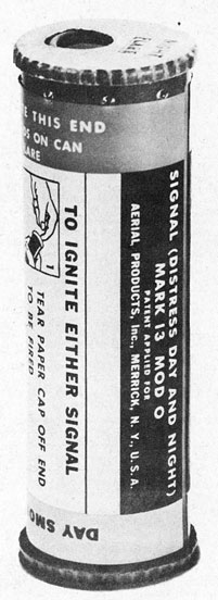
Signal (Distress Day and Night) Mk 13 Mod 0:
The Signal, Mk 13 Mod 0 1s a combination distress signal for use under day or night distress conditions, or both. Because of its small size it can be carried conveniently in pockets of life-vests, flight suits or life rafts. It is particularly adapted for use by aircraft pilots downed at sea.
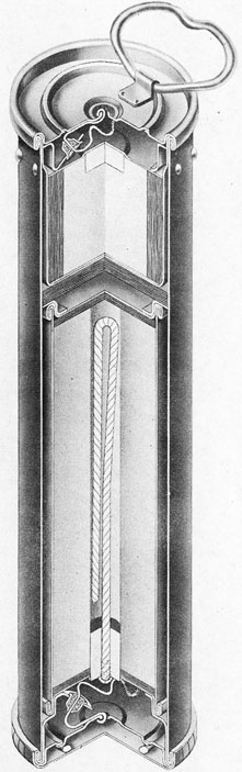
General: This signal is similar in appearance and operation to the Signal, Distress, Smoke, Hand, AN Mark 1 Mod 1. Whereas the Signal AN Mark 1 Mod 1 is a smoke signal for use only under daytime distress conditions, the Signal Mk 13 Mod 0 contains the same orange smoke canister in addition to a pyrotechnic flare pellet for use under night distress conditions. The signal consists of a metal cylindrical outer case 5-1/8 inches long and 1-5/8 inches in diameter. Weight of the signal is 6.4 ounces. Both ends of the metal tube are closed by a soldered cap to which is attached a pull ring for insertion of the index finger. Upon removal of the soldered closing cap, a brass wire attached to the bottom thereof is pulled through a small cup coated with a friction igniting composition. This action results in igniting the pyrotechnic flare or the smoke composition depending on which pull ring is removed. Smoke emission time is approximately 18 seconds. Flare burning time is 18 to 20 seconds. Average candle power of the burning flare is 3,000 candles. The soldered caps on both ends of the signal are covered with a paper cap in order to prevent the possibility of an accidental pull on the pull rings. These paper caps should be removed sometime before actual use in order that the pull ring will be readily accessible when desired.
Operation: The signal body carries an illustrated decalcomania which shows in detail the method of operation. The flare end of the tube (for night use) can be identified by a series of embossed projections extending around the case approximately 1/4" below the closure.
The following steps should be followed in the operation of this signal:
(a) Having determined which end of the signal it is desired to use (smoke for day, flare for night) remove the paper cap which is glued to the signal body. (This cap should ordinarily be removed before the time of actual use, )
(b) Point signal away from face and give a quick pull on the pull ring which will come away from the can, thereby igniting the composition.
NOTE; If unable to remove the soldered cap in this manner, bring the pull ring down over the rim of the can and press down, using the ring as a lever to break the seal.
(c) Hold signal at arm's length at an angle of about 30° from the horizontal to prevent the possibility of hot drippings or discharge falling on the hand.
After one end has been used, the signal should immediately be doused in the water in order to cool the metal parts. The signal should then be retained for use of the opposite end when required. Each section of the signal is well waterproofed and insulated against transfer of heat from one section to the other.
Stowage: The Signal, Mk 13 Mod 0 should be stowed in a cool, dry place, in accordance with standard pyrotechnic stowage rules.
Packing: These signals are shipped from the place of manufacture in wooden boxes containing 100 signals.
Weight of the box containing the 100 signals is approximately 70 pounds. It is contemplated that a metal can to carry four (4) Signals, Mk 13 Mod 0 suitable for stowage on life boats, floater nets etc. will also be made available at a later date.
Safety Precautions:
(a) When igniting the signal, it must be pointed away from the body and face at all times.
(b) Signals should not be subjected to rough handling.
(c) Never attempt to ignite both ends of the signal at the same time.
(d)If possible, the signal should be doused in water immediately after using one end, before using the opposite end.
DISTRIBUTION
Requests for additional copies of OP 1177 Ch. 3 should be submitted on NAVORD FORM 1, ORDNANCE PUBLICATIONS AND FORMS REQUISITION, to the nearest Ordnance Publications Distribution Center: Navy Yard. Wash. 25, D.C.; Adak, Alaska; Mare Island, Calif.; Pearl Harbor, T.H.; Guam Island, Marianas; Manus Island, Admiralty Islands. Distribution Center mailing addresses should be obtained from List 10nn of the Standard Navy Distribution List, or from the reverse side of NAVORD FORM 1.
Standard Navy Distribution List No. 29 (C) and 32 (R) 1 copy unless otherwise noted.
1.; 2. a, c, d, f, h, i, 1, n, o, r, s, t, u; 3. except kk; B3. (5 copies), LIONS, CUBS, ACORNS; 5. b (London only); 6. a, b, c; 7. a-1, q-t, x, z, dd, ee; 7. (3 copies), p; 8. a*, b, f, 115, 1, n, (SPECIAL L1STS K, BB), r, u, v, hh; 10. f*, g*, i, j, m*, s, t, u, nn*, qq, ss; 11. (BuShips, BuAer, BuDocks, CNO, ComdtMarCoris) 12. a, b; 13. a(1), (2), (15), b(1), (5), (6), c(1), (3), (4), (6), (8), (10); 14, a-e, g, h, q.
* Applicable addressees.
2
FIG. 1. SIGNAL (DISTRESS DAY AND NIGHT) MK 13 MOD. 0
1
RESTRICTED
NAVY DEPARTMENT BUREAU OF ORDNANCE WASHINGTON 25, D. C.
To all holders of Ordnance Pamphlet 1177 insert change; write on cover 'Change 4 inserted' Approved by The Chief of The Bureau of Ordnance
OP 1177 CHANGE 4
25 August 1945
2 Pages - Page 1
ORDNANCE PAMPHLET 1177
is changed as follows:
SURFACE PYROTECHNICS AND PROJECTORS
After Paragraph 78, add the following:
When firing this signal from the new Hydraulic Type Air-operated Signal Ejector, the following operating procedure should be followed:
(a) Load the signal in the barrel and push it forward toward the muzzle until the spring loaded de-tent drops down behind the signal. The detent is located about 9" from the breech end of the ejector.
(b) The safety pin should not be removed from the signal until the signal has been pushed into the tube past the detent, and the breech door is about to be closed.
(c) For convenience in removing the safety pin ring, a lanyard may be attached to the ring prior to loading the signal in the tube.
After Paragraph 79b, add the following:
(c) When firing this signal from the new Hydraulic Type Air-operated Signal Ejector, the safety pin should not be removed until the signal has been loaded into the tube to a point beyond the spring detent.
Insert attached page 42a (Figure 30a).
42a
Figure 30a
SIGNAL (DISTRESS DAY AND NIGHT)
MARK 13 MOD 0