70. Pyrotechnic equipment issued to submarines include: submarine emergency identification signals, submarine float signals, submarine identification flares, pistol rocket signals, submarine rocket pistols, Pyrotechnic Pistols AN-M8, and Navy blue lights. Descriptions and instructions for the use of each of the above items will be found in the paragraphs following.
Submarine Emergency Identification Signal, Star, Mk 2 Mod 2 and Mk 3 Mod 0
71. These signals are for either day or night use. They are for use exclusively with the submarine signal ejector and are ejected by compressed air. On rising to the surface of the water, Submarine Emergency Identification Signals Mk 2 Mod 2 and Mk 3 Mod 0 project a Single Star Grenade Mk 5 to a height of 250 feet, where a parachute opens and supports the star, which burns for approximately 13 seconds. The complete signal is available in one of three colors, RED, GREEN or YELLOW. See Fig. 32.
(a) Submarine Emergency Identification Signals Mk 2 Mod 2 and Mk 3 Mod 0 consist of a buoyant tube of aluminum 18.5 inches long and three inches in diameter, which contains the Single-Star Grenade Mk 5 Mod 0. One end is closed with an ogive nose cap. The other end carries the ignition device, which consists of a firing pin lever and spring, a tripping lever and pin, a lock spring and pin, and a safety cotter pin which is of the ring-pull type. Above the firing-pin lever is the primer in its holder, which flashes into the combination delay unit and ejection charge. See Fig. 32.
(b) Early issues of Submarine Emergency Identification Signal Mk 2 Mod 2 contained either Smoke Grenade Mk 3, for day use, or Three-Star Grenade Mk 4, for night operation. Both these signals are now obsolete, and the current issue with the Single-Star Grenade Mk 5 is for both day and night use.
(c) Submarine Emergency Identification Signals Mk 2 Mod 2 and Mk 3 Mod 0 should not be ejected at depths greater than 160 feet, as the time required to reach the surface is limited to the 27 seconds allowed by the time fuze.
Operation
72. Complete instructions for firing Submarine Emergency Identification Signal Mk 2 Mod 2 will be found in paragraphs 77, 78, and 79, covering the use of submarine signal ejector.
Packing
73. Submarine Emergency Identification Signals Mk 2 Mod 2 and Mk 3 Mod 0 are shipped in wood containers holding 25 signals. The shipping weight of the container is approximately 100 pounds.
Stowage
74. For shipboard stowage Submarine Emergency Identification Signals Mk 2 Mod 2 and Mk 3 Mod 0 should be placed in a gasket sealed metal container, which holds 12 signals and is known as Packing Box Mk 2 for Submarine Emergency Identification Signals. Should this item not be available, a three-inch cartridge tank may be substituted.
Safety Precautions
75. These signals should be inspected frequently. Any corrosion of the safety mechanism is cause for disposal by dumping in deep water as described in paragraph 17.
(a) Should any signal be removed from submarine signal ejector without being fired, the safety cotter pin must be replaced immediately after ascertaining that the firing mechanism is undamaged, and that the firing-pin lever is in place.
(b) The signal case should be thoroughly dried, and the nose cap should be inspected to make sure that its sealing effectiveness is unimpaired.
46
Figure 32.-Submarine Emergency Identification Signal, Mk 2 Mod 2 (Similar to Mk 3 Mod 0)
47
(c) The Single Star Grenade Mk 5 is installed in Submarine Emergency Identification Signals Mk 2 Mod 2 and Mk 3 Mod 0 by the depot and should not be removed therefrom.
(d) Signals of this type now in service are expected to give only 50 per cent performance. For this reason, at least three signals should be fired in actual operations for each star required.
Alternate Signals
76. Submarine Emergency Identification Signal, Star, Mk 2 Mod 2 is gradually being replaced by Submarine Emergency Signal, Star, Mk 3 Mod 0 and Submarine Emergency Signal, Star, Mk 3 Mod 1.
(a) Submarine Emergency Identification Signal, Star, Mk 3 Mod 0 differs from Submarine Emergency Identification Signal, Star, Mk 2 Mod 2 only in the method of expulsion of the inner grenade. Procedure for operation, packing, stowage, and safety precautions are exactly as described in the paragraphs covering those details above.
(b) Submarine Emergency Identification Signal, Star, Mk 3 Mod 1 is similar to the above signals described in paragraph 71, except that it may be ejected at depths up to 285 feet. It carries a time fuze of 54 seconds' duration. Otherwise, all instructions given for Submarine Emergency Identification Signals Mk 2 Mod 2 and Mk 3 Mod 0 apply.
Submarine Signal Ejector
77. The submarine signal ejector is a device which is usually located in the control room of submarines, and extends through the shell of the vessel to the superstructure deck, so that the muzzle is flush with the deckplates. It is designed to eject, by compressed air, submarine emergency identification signals clear of the vessel, when surfaced or submerged. The ejector mechanism is similar to, but smaller than, the conventional torpedo tube. It ejects the signals by air pressure from the 200-pound air line on submarines of the newer classes and from the 100-pound air line on submarines of earlier types. An auxiliary air connection to the outboard section of the ejector permits the blowing out of water from the barrel after a
signal has been fired. This water is blown through a one-inch drain line into the control room bilge. A muzzle door and breech door are operated in the same manner as those of torpedo tubes. The muzzle door is of the swinging-gate type with circular valve discs. The breech door is also of the swinging-gate type but has a valve of the screw-down disc type and seals with a rubber gasket insert. The doors operate by a horizontal operating lever. This lever has a cam so connected that it forms a mechanical interlock which allows only one of the two doors to operate at any one time and holds the submarine emergency identification signal in place by a spring stop until the breech door closes. The ejecting valve is of the quick-opening type and interlocked with the muzzle door so that it is not possible to operate the ejector with that door closed. As the emergency identification signal passes through the barrel, the extension of its tripping lever rides in a groove which extends throughout the length of the barrel to a point just inside the muzzle. There the tripping lever is drawn back and fires the primer of the signal as it leaves the muzzle. Details of the construction of Submarine Signal Ejector will be seen in Fig. 33.
Operation
78. Before operating the submarine signal ejector, make certain that the ammunition is in perfect order, that in the removal of the signals from stowage they have not been dropped, and that the firing pin and tripping levers have not been forced, struck, or pulled. Be sure that the case of the signal is not dented and that the nose seal is intact. Place the signal carefully into the breech of the barrel, with the tripping lever in the groove. After the breech is closed, the muzzle door may be opened to flood the ejector and the signal may be fired. After firing, close the muzzle door, blow out the barrel into the control room bilge, and make ready for the next loading. Fig. 33 shows the progressive operating procedure.
Safety Precautions
79. In operating the submarine signal ejector, the following precautions must be observed:
(a) If it is found necessary to operate the ejector when the vessel is surfaced, all
48
Figure 33.-Submarine Signal Ejector
49
precautions must be taken to see that personnel on deck are well clear of the ejector muzzle, and of the deck area on which the ejected signal light or parts might fall. It should be impressed on all personnel that when the signal projects the grenade, the recoil of the signal case is violent. If a signal lands accidentally on or near the deck, all personnel should stand clear of the rear end of the case, as well as the forward end, until after the grenade has been projected.
(b) When carrying or loading the signals, care must be taken never to point them directly towards or away from other personnel, and to stand clear of the ejector breech while loading.
Submarine Float Signal Mk 1 Mod 1
80. Submarine Float Signal Mk 1 Mod 1 is for day use and is similar in appearance and operation to submarine emergency identification signals, but does not project a grenade. It is ejected from the submarine signal ejector and, on rising to the surface, floats and emits either black smoke or green smoke, for about 15 seconds. The base of Submarine Float Signal Mk 1 Mod 1 contains the same firing mechanism as submarine emergency identification signals, and the closing cap is marked to show the color of the smoke. Fig. 34 shows the arrangement of the components and the firing mechanism of the signal. The delay train within the signal has a time lag of approximately 22 seconds from the time of ejection by the signal ejector to the time when the primer is fired. Visibility in good weather is approximately six miles.
Operation
81. This signal is handled and fired in the same manner as submarine emergency identification signals, and full instructions are to be found in paragraphs 77, 78, and 79. Submarine Float Signal Mk 1 Mod 1 is designed for ejection at depths up to 170 feet and should not be fired
below that depth. A new signal to be known as Submarine Float Signal Mk 2 Mod 0 will soon be made available for ejection at depths up to 280 feet.
Packing
82. Submarine Float Signal Mk 1 Mod 1 is packed in wood containers in units of 25 signals. Each signal is marked on the closing cap to indicate the color of the smoke.
Stowage
83. The general rules for the stowage of pyrotechnics detailed in paragraphs 9 to 12, inclusive, apply to Submarine Float Signal Mk 1 Mod 1. No metal stowage boxes are supplied for this item, as is done in the case of Submarine Emergency Identification Signals Mk 2 Mod 2.
Safety Precautions
84. All precautions given for the use of submarine emergency identification signals and for the submarine signal ejector must also be taken with Submarine Float Signal Mk 1 Mod 1.
Submarine Identification Flares Mk 10 Mod 0, Mod 1, and Mod 2
85. Submarine Identification Flares Mk 10 Mod 0, Mk 10 Mod 1, and Mk 10 Mod 2 differ only as to the color of the signal they provide. All are housed in a seamless steel tube 9.75 inches long and two inches in diameter, closed by a steel cup riveted to one end and by a casting at the other end. The casting houses the closure disc and the primer, and is attached to the firing mechanism, which extends along the side of the steel tube. The flare is mounted in a bracket fixed to the conning tower of the submarine. It is fired by a lanyard and burns with a brilliant colored flame about nine inches high, which lasts approximately two minutes. The firing mechanism consists of a brass housing two inches long which contains a firing pin,
50
Figure 34.-Submarine Float Signal Mk 1 Mod 1
51
Figure 35.-Submarine Identification Flare Mks 10, 11, and 12, and Mods
52
a firing pin spring, and a brass shaft. The brass shaft is interlocked to the firing pin by a beveled keyway. A pull ring is attached to the lower end of the brass shaft, and a safety cotter pin secures the housing to it. Before firing the flare, remove the safety cotter pin. A strong downward pull on the lanyard is necessary to allow the firing pin to slip out of the keyway. The firing spring then drives the firing pin upward, firing the primer, which ignites a small charge of black powder. The resultant pressures are sufficient to blow off the steel cup at the top of the tube, exposing the colored flare. See Fig. 35.
Operation
86. Submarine Identification Flares Mk 10 and Mods are mounted to brackets fixed to the conning tower of the vessel. To fire, first remove the safety pin and then give the lanyard a sharp pull downward. When mounting, the safety pin should be straightened to facilitate its quick removal when ready to fire.
Packing
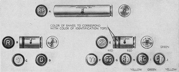
87. Twenty submarine identification flares are packed in a wood container. Each flare is marked with a colored band on the steel case to show the color of the signal.
(a) Submarine Identification Flare Mk 10 is marked with a RED band and burns with a RED flame.
(b) Submarine Identification Flare Mk 10 Mod 1 is marked with a GREEN band and burns with a GREEN flame.
(c) Submarine Identification Flare Mk 10 Mod 2 is marked with a YELLOW band and burns with a YELLOW flame.
Stowage
88. The general rules for the stowage of pyrotechnics detailed in paragraphs 9 to 12, inclusive, apply to Submarine Identification Flares
Mk 10 and Mods. Flares which have been exposed to spray should be carefully dried before returning them to ready service magazines for future use.
Safety Precautions
89. In handling and firing Submarine Identification Flares, the following safety precautions should be taken:
(a) Because of the possibility of detonation, particularly of Submarine Identification Flare Mk 10 Mod 2 (GREEN), all personnel in the vicinity of the flare should take cover immediately before firing. Some submarines of the fleet have been equipped with a shield for shielding the flare on the bracket. This shield should be obtained, if possible.
(b) A few drops of light oil should be supplied in the holes of the firing mechanism just prior to firing. If the flare is exposed to weather or spray for any appreciable time, this oil will be essential to the smooth operation of the firing mechanism.
(c) If they are not to be fired, flares should be removed from the brackets before the vessel. is submerged, whenever possible. Flares exposed to submersion below periscope depth should be detached on surfacing and cast overboard.
(d) All flares which have been exposed to weather and spray to such an extent that they show deterioration should be cast overboard. Any evidence of corrosion beneath the bracket clamps, or along the joint of the casting with the steel tube, is sufficient cause for disposal of the flare.
Submarine Identification Flares
Mk 11 and Mods 1 and 2
90. Submarine Identification Flares Mk 11 and Mods are similar in all respects to Submarine Identification Flares Mk 10 and Mods, except that the Flares Mk 11 burn intermittently, while Flares Mk 10 burn continuously.
53
Instructions for the operation, stowage, and safety precautions applicable to Submarine Identification Flare Mk 10, apply to Submarine Identification Flare Mk 11 and Mods.
(a) Submarine Identification Flare Mk 11 is marked with a RED mark and burns in four increments of ten seconds with a RED flare and with five-second blackouts between the first, second, third, and fourth ten-second periods of burning.
(b) Submarine Identification Flare Mk 11 Mod 1 is marked in GREEN and burns exactly as in (a) above, except that the signal light will be GREEN.
(c) Submarine Identification Flare Mk 11 Mod 2 is similar to those above in (a) and (b), except that it is marked in YELLOW and burns with a YELLOW flame.
Packing
91. Submarine Identification Flare Mk 11 is packed in wood containers similar to those in which Submarine Identification Flare Mk 10 is packed. Each flare is marked for identification.
Submarine Identification Flares Mk 12 and Mods 1 and 2
92. Submarine Identification Flares Mk 12 and Mods are similar in all respects to Submarine Identification Flares Mk 11 and Mods, except that Flares Mk 12 burn intermittently in alternating colors. All are similar in construction to Submarine Identification Flares Mk 10 and Mods; and the instructions for operation, stowage, and safety precautions applicable to that mark apply to Submarine Identification Flares Mk 12 and Mods.
(a) Submarine Identification Flare Mk 12 Mod 0 is marked with four colored bands; RED, GREEN, RED, and GREEN. It burns as follows; RED, ten seconds; blackout, five seconds; GREEN, ten seconds; blackout, five seconds; RED, ten
seconds; blackout, five seconds; and GREEN, ten seconds.
(b) Submarine Identification Flare Mk 12 Mod 1 is identical to (a) , except that it is marked with four colored bands; RED, YELLOW, RED, and YELLOW. It burns in the same manner as in (a) , except that the flame colors match the bands in that order.
(c) Submarine Identification Flare Mk 12 Mod 2 is identical to (a), except that it is marked with four colored bands; GREEN, YELLOW, GREEN and YELLOW. It burns in the same manner as in (a), except that the flame colors match the bands in that order.
Packing
93. Submarine Identification Flare Mk 12 is packed in wood containers similar to those in which Submarine Identification Flare Mk 10 is packed. Each flare is marked.
Alternate Signal
94. Under consideration by the Bureau is the possibility of using ships emergency identification signals on board submarines as a substitute for Submarine Identification Flares Mk 10 and Mods. A quantity of ships emergency identification signals, as described in paragraph 27, has been made available for use for submarines in an attempt to determine whether this type of signal will result in improved recognition communications between submarine and friendly aircraft. The standard Ships Emergency Identification Signal Mk 1, as described in paragraph 27a, is being issued for this purpose with the addition of a YELLOW colored signal, as will be seen in paragraph 27a. Standard Ships Emergency Identification Signal Mk 1 Mod 0 includes only RED, WHITE, and GREEN. For submarine purposes, RED, GREEN, and YELLOW signals will be available. The signals will be fired in the usual manner from the Ship's Projector Mk 1 Mod 0 as described in paragraph 32. Signals of this type
54
Figure 36.-Pistol Rocket Signal Mk 1, Comet
55
for use from submarines are being given only limited distribution and, if satisfactory, will be issued universally as a supplement to the Submarine Identification Flare Mk 10 and Mods.
Pistol Rocket Signal Mk 1, Comet
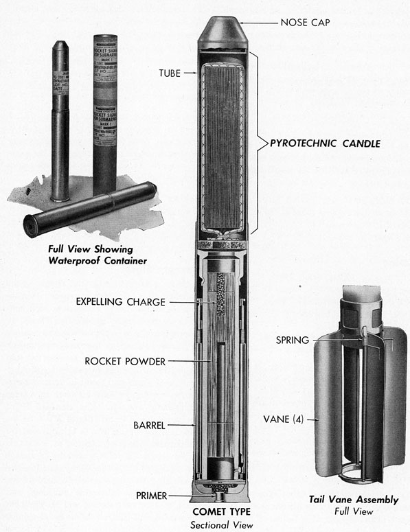
95. Pistol Rocket Signal Mk 1, Comet, is used for emergency identification by a surfaced submarine. It is fired from Submarine Rocket Pistol Mk 1 Mod 0, which is similar to Signal Pistol Mk 5 in operation. Pistol Rocket Signal Mk 1, Comet, may also be fired from Pyrotechnic Pistol ANM8. The signal consists of an aluminum case in two sections. It is 14 inches long. The lower section is eight inches long and 1.5 inches in diameter. It houses a standard Primer Mk 5, a felt pad and one-gram charge of black powder, which acts as an auxiliary expelling charge and ignites the rocket. The upper section of the signal is six inches long and of lesser diameter than the lower section. It houses the signal chamber, which carries the pyrotechnic candle, and is attached to the rocket tube, which contains a solid black powder charge of 58 grams, extending into the lower section. At the base of the rocket tube are attached four folding vanes four inches long and
0.5 inches wide. Details of the construction of the Pistol Rocket Signal Mk 1, Comet, will be seen in Fig. 36. The signal is available in three colors, RED, GREEN, or YELLOW. It burns for approximately 12 seconds as a single star while falling freely to the surface. The candlepower of the signal is rated at 45,000, giving night visibility in good weather up to ten miles.
Operation
96. Detailed instructions for firing Pistol Rocket Signal Mk 1, Comet, will be found under the paragraphs covering Submarine Rocket Pistol Mk 1 Mod 0 and Pyrotechnic Pistol ANM8. When the signal is fired, the primer ignites the one-gram auxiliary expelling charge, which projects the upper section of the signal to a height of 30 feet. There the rocket element ignites and the signal rises to 650 feet, where the pyrotechnic candle ignites, furnishing the colored star. The vanes give the rocket stability as it rises, and the rocket charge leaves a trail of white light similar to the tail of a comet, from which the signal gets its name. The single star does not have parachute suspension, but falls freely to the surface during its 12 seconds of burning.
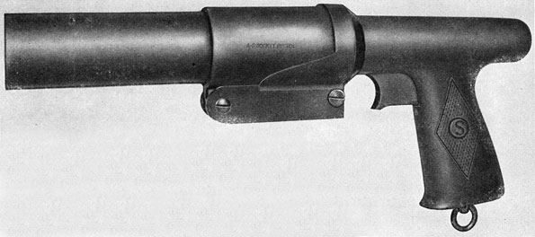
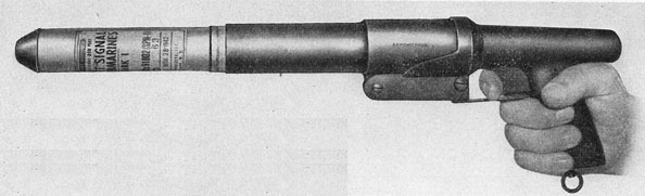
Figure 37.-Submarine Rocket Pistol Mk 1 Mod 0
56
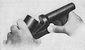
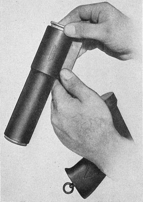
Figure 38.-Opening Breech for Submarine Rocket Pistol Mk 1 Mod 0
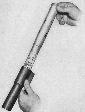
Figure 39.-Loading Submarine Rocket Signal Mk 1 (Comet)
Packing
97. Each Pistol Rocket Signal Mk 1, Comet, is packed in a waterproof mailing tube container. Fifty such containers are shipped by Naval Ammunition Depots in wood cases. A metal container holding 12 signals and their mailing tube containers is available for issue to submarines. The signals must not be removed from their individual containers until ready for use. Colors of the signal stars are marked on the paper containers.
Stowage
98. The general rules for the stowage of pyrotechnics detailed in paragraphs 9 to 12, inclusive, apply to Pistol Rocket Signal Mk 1, Comet. The special metal container should be obtained if available, and the 12 signals kept in readiness for immediate use. Signals which have been removed from their individual containers but not used, must be dried thoroughly before re-inserting them for stowage.
Safety Precautions
99. In firing Pistol Rocket Signal Mk 1, Comet, from the Submarine Rocket Pistol or Pyrotechnic Pistol AN-M8, always point the pistol slightly outboard and away from surrounding personnel or vessels. This caution should also be taken when loading new signals into the breech of the pistol.
(a) Faulty or misfired signals should never be disassembled.
Figure 40.-Ready to Fire Submarine Rocket Pistol Mk 1 Mod 0
57
Figure 41.-Extracting Expended Shell of Submarine Rocket Signal Mk 1 (Comet)
Alternate Signals
100. Prior to the issue of Pistol Rocket Signal Mk 1, Comet, small quantities of Submarine Rocket Signal, Single Star, shown in Fig. 62, were issued and may be still available at various Naval Ammunition Depots. They are no longer authorized for issue to submarines. They are similar in operation to Pistol Rocket Signal Mk 1, Comet, except that the star was suspended from a parachute. This signal is now designated as Pistol Rocket Signal Mk 1 Mod 1.
Submarine Rocket Pistol Mk 1 Mod 0
Submarine Rocket Pistol Mk 1 Mod 0 (Fig. 37) is supplied for use with pistol rocket signals only. It is a breech-loading pistol, 13 inches long, with a bore of 1.5 inches, and is made up of three main assemblies: the barrel, the breech, and the grip. Figs. 38, 39, 40, and 41 show operational sequence of loading and firing. The barrel is die-cast of light metal and hinged to the breech for loading. It includes a hinge cam which operates the cartridge ejector. The breech assembly is die-cast of the same metal as the barrel assembly and includes the breech latch and lock, which operate by pressure of the thumb. The grip assembly is of bakelite. It houses the metal parts of the firing mechanism, which includes the firing pin and springs, the trigger, etc., as shown in Fig. 42; held in place by a tang nut.
Care, Cleaning, and Lubrication
102. Submarine Rocket Pistol Mk 1 Mod 0 should be kept in serviceable condition at all times and cleaned thoroughly after each using. All parts should be wiped with a light oil impregnated cloth and exposed parts should be wiped with a dry cloth after assembly. The barrel should be swabbed with a cloth dampened with acetone or other suitable solvent to remove powder residue.
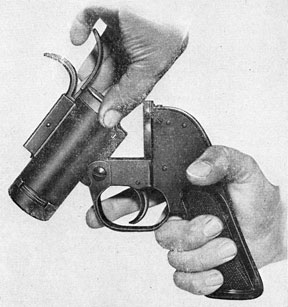
Pyrotechnic Pistol AN-M8
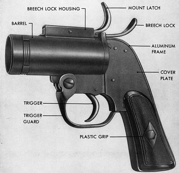
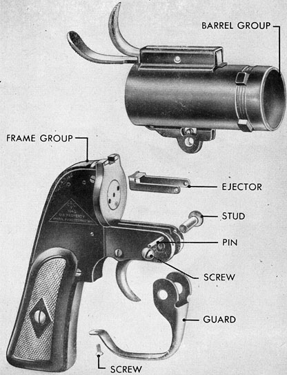
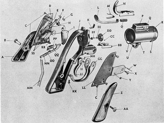
103. The Pyrotechnic Pistol AN-M8 (Fig. 43) is a breech-loading, double-action signal pistol. The barrel, hinged to the frame, is held in firing position by the breech lock. The plastic grips, back plate, and cover plate fasten to the aluminum frame and act as a housing for the
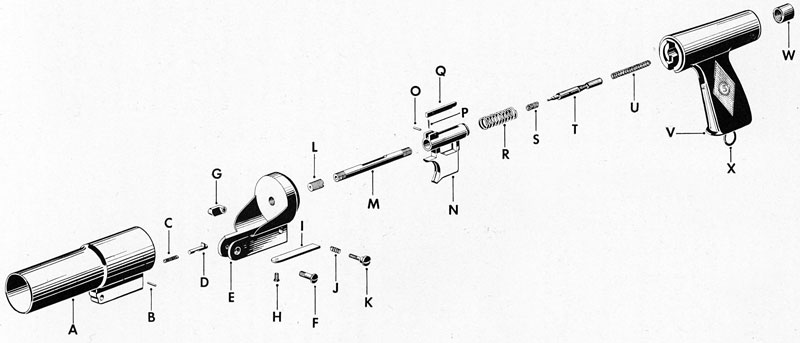
M-FIRING PIN TUBE
N-TRIGGER
O-COCKING LEVER PIN
P-COCKING LEVER SPRING
Q-COCKING LEVER
R-TRIGGER SPRING
S-RECOIL SPRING
T-FIRING PIN
U-FIRING PIN SPRING
V-PLASTIC HANDLE
W-TANG NUT
X-BUTT RING
Figure 42.-Submarine Rocket Pistol Mk 1 Mod 0 (Exploded View)
59
Figure 43.-Pyrotechnic Pistol AN-M8
firing mechanism. The principal parts of this pistol are shown in Figs. 43 and 44. For sequence of loading and firing, see Figs. 45, 46, 47, and 48.
Care, Cleaning, and Lubrication
104. Pyrotechnic Pistol AN-M8 must be kept in serviceable condition at all times. It should be cleaned thoroughly and all principal parts (see Fig. 44) wiped with a cloth impregnated with a light machine oil after each using. When assembled, the exposed parts should be wiped with a dry cloth. The barrel should be swabbed with a cloth dampened with acetone or other solvent to remove the powder residue.
60
Figure 44.-Pyrotechnic Pistol AN-MB
Safety Precautions
105. When loading and firing any pyrotechnic pistol, care should be taken never to point it in the direction of other personnel or vessels. With rocket signals, some recoil of the pistol will be encountered. Therefore, the pistol should be held so that the elbow is slightly bent, to absorb the shock of the recoil. Pyrotechnic pistols should never be used for firing any ammunition other than that prescribed for use in them.
61
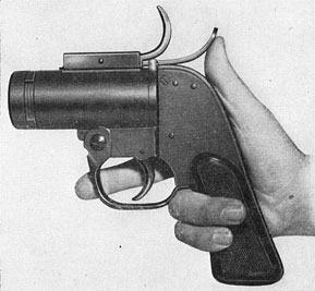
Figure 45.-Tripping Breech Lock of Pyrotechnic Pistol AN-M8
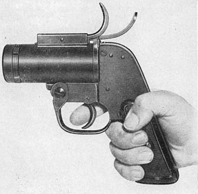
Figure 47.-Firing
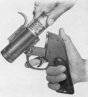
Figure 46.-Loading
Figure 48.-Extracting Expended Shell
62
A-L.H. GRIP
B-GRIP STUD
C-COVER PLATE AND BACK PLATE SCREWS
D-BACK PLATE ASSEMBLY
E-HAMMER SPRING
F-SAFETY LEVER
G-SAFETY LEVER SPRING
H-BARREL PIVOT STUD
I-HAMMER
J-FRAME
K-BARREL HINGE SPRING
L-BREECH LOCK
M-BREECH LOCK SPRING
N-MOUNT LATCH
O-LATCH SPRING
P-BREECH LOCK HOUSING
Q-BREECH LOCK PIN
R-BARREL
S-BARREL RECOIL LUG
T-BARREL HINGE
U-EJECTOR SPRING RETAINING PIN
V-EJECTOR SPRING
W-EJECTOR PIN
X-BARREL PIVOT STUD SCREW
Y-TRIGGER SCREW Z-R. H. GRIP
AA-GRIP SCREW
BB-EJECTOR
CC-BUSHING RETAINER SET SCREW
DD-BUSHING RETAINER
EE-FIRING PIN SPRING FF-FIRING PIN
GG-TRIGGER GUARD
HH-BARREL HINGE SPRING SCREW
II-TRIGGER SLIDE PIN
JJ-TRIGGER
KK-TRIGGER GUARD SCREW
LL-COVER PLATE MM-TRIGGER SPRING
NN-TRIGGER SLIDE
OO-TRIGGER PAWL SPRING
PP-TRIGGER PAWL
QQ-TRIGGER PAWL PIN
RR-PAWL TRIP ROLLER
SS-PINS
106. Motor torpedo boat pyrotechnics include float flares, for silhouetting enemy targets so that other vessels can train on them, and a number of signal cartridges for identification or inter-communication between the motor torpedo boat and other vessels or aircraft.
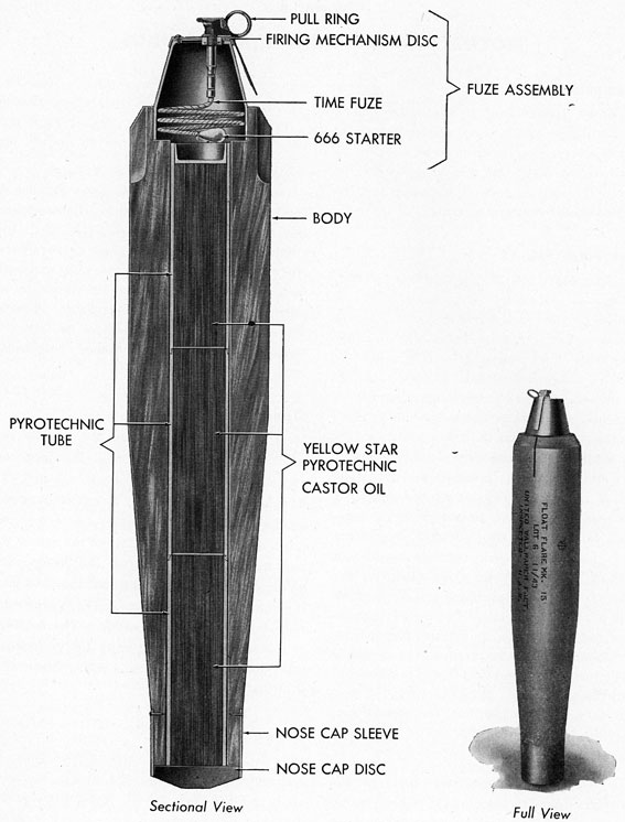
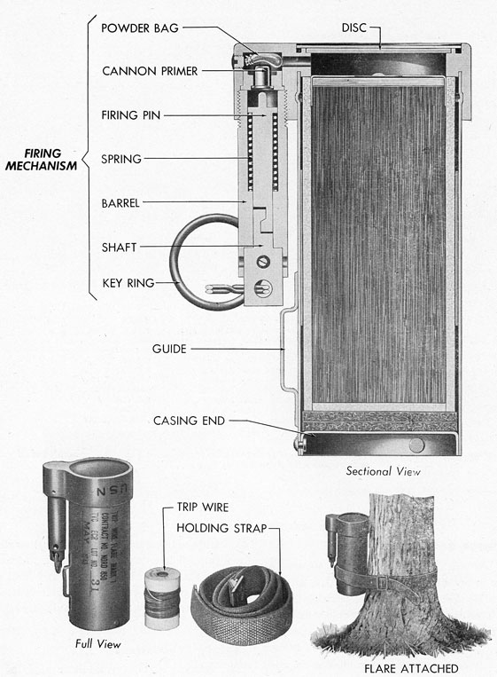
Float Flare Mk 15
107. Float Flare Mk 15, Fig. 50, is a 150,000-candlepower floating pyrotechnic.It is launched by hand, and burns five minutes with a yellowish flame some 26 inches high and four inches wide, five minutes after it is launched. The flare weighs 26 pounds, is approximately 37.2 inches long, has a maximum diameter of 6.5 inches, and is launched by two men. One pulls the safety ring as the other holds a safety lever while casting the flare overboard. The entire unit consists of a bomb-shaped pine wood body 32 inches long, closed at one end by a steel nose cap and at the other by a cone-shaped fuze housing approximately five inches long. The fuze housing carries a 3.5-foot length of time fuze, which gives a delay of five minutes between the launching and the ignition of the pyrotechnic candle. The candle, consisting of barium nitrate, aluminum, magnesium, and sodium oxalate, is contained in a plastic tube 31 inches long and 2.75 inches in diameter, within the wood body. While burning, the flare floats in a vertical position, the water level being nine inches from the top of the firing mechanism.
(a) Only limited operational tests in silhouetting ships with this flare have been made. It is established, however, that one flare placed some 1500 yards behind a torpedo boat will
silhouette that boat for another vessel, at a distance of two miles in clear night weather. It has been found that such silhouetting is more effective with slight overcast or surface haze conditions prevailing.
(b) The placing of the flares in pattern, depending on the size and shape of the target and the atmospheric conditions, has also been studied. It is believed that three or more flares, spaced at about 300-yard intervals, will satisfactorily silhouette a ship when viewed by another ship from the flank opposite. Specific details of pattern for practical use must be worked out by the various torpedo boat squadrons.
Operation
108. To launch Float Flare Mk 15, the man who is to launch it must hold the flare horizontally, with the fuze pointed outboard. The flare is held with the safety lever firmly pressed against the side of the case. A second man must then grip the pull ring of the safety pin, and withdraw it just before launching. Still holding the safety lever against the fuze housing, the first man then casts the flare overboard, to leeward whenever possible. The releasing of the safety lever will ignite the primer and the time fuze, and the flare will operate after a five-minute delay.
Stowage
109. General stowage instructions, as described herein in paragraphs 9 to 12, inclusive, apply to Float Flare Mk 15. Precautions should be taken not to expose these flares to direct sunlight or to excessive moisture.
64
Figure 50.-Float Flare Mk 15
65
Packing
110. Float Flare Mk 15 is packed and shipped in an individual wood case. It should not be removed from the shipping case until ready to use. Future issues will be in individual watertight metal cases similar to six-inch powder tanks.
Safety Precautions
111. In handling and using Float Flare Mk 15, the following safety rules must be enforced:
(a) These flares are for exclusive use by surface craft and must never be dropped from aircraft. A modification of this flare is now being designed for use by aircraft.
(b) In handling the flare, operating personnel should be instructed not to grasp it by its firing mechanism. A strong pull on the firing mechanism may detach that element from the. rest of the flare.
(c) While launching, the operator must hold the flare horizontally, with the fuze housing pointed outboard, while the safety pin is being pulled.
(d) The safety lever must be held firmly against the side of the fuze housing and released only at the moment the flare is cast overboard. Should the safety pin be pulled and it be decided not to use the flare, the pin may be replaced only if the operator is certain that the lever has not been sufficiently released to prime the fuze.
Float Flare Mk 15 Mod 1
112. Float Flare Mk 15 Mod 1, not yet under procurement, is similar in all respects to Float Flare Mk 15, except that it has a mechanical clockwork timing device which replaces the Ensign Bickford time fuze on the Float Flare Mk 15. This clock fuze allows the flare to be set so that it will ignite at any interval between one and 30 minutes after launching. Generally
speaking, Float Flare Mk 15 Mod 1 has the same weight, dimension, and use as Float Flare Mk 15, except that the cone-shaped fuze housing of the Float Flare Mk 15 is replaced by a suitable housing for the clock fuze.
Operation
113. One man can operate Float Flare Mk 15 Mod 1. In order to launch it, first set the timing device at the setting ordered, second, remove the safety pin, and then cast the flare overboard. The clock fuze will begin functioning when the safety pin is withdrawn.
Stowage, Packing, and Safety Precautions
114. Float Flare Mk 15 Mod 1 is stowed, packed, and handled with the same safety precautions as Float Flare Mk 15, as given in paragraphs 109, 110, and 111.
Aircraft Double Star Signal Cartridges
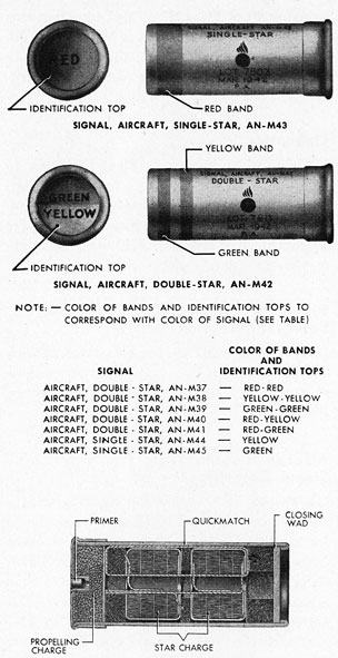
115. Three types of double star signal cartridges are now being issued to motor torpedo boats for identification to friendly aircraft or other friendly surface vessels. They are the Signal Cartridge Mk 3 Mod 3, Aircraft Double Star Signals ANM28 to ANM33, inclusive, and Aircraft Double Star Signals ANM37 to ANM42, inclusive. All are used with Pyrotechnic Pistol ANM8, which is described in the section of this manual under Submarine Pyrotechnics, paragraphs 103 to 105. The signal cases and their internal contents will be seen in Figs. 51 and 52. All these signals are 1.5 inches in diameter and between three and four inches long. Some have shell cases of aluminum, and others have paper or plastic shell cases. It is recommended that the aluminum shell cases be saved after firing, and returned to the nearest ammunition depot or air station, when possible. The aluminum shell signals all have bases
66
Figure 51.-Aircraft Star Signals
grooved to fit the ejector of Pyrotechnic Pistol AN-M8. See Fig. 44.
(a) Signal Cartridge Mk 3 Mod 3, Fig. 51, is made up of a standard 1.5-inch shotgun-type case with a brass base to hold the primer. Two colored bands around the shell indicate the colors of the two stars, in order of appearance as read from the closing wad toward the base.
The colors are also indicated on the closing wad. The signals are available in color combinations shown in Fig. 51. No means of color identification in darkness have been provided.
(b) Aircraft Double Star Signals AN-M28 to AN-M33, are differentiated by number to show the color combination of the stars within them. They are made in aluminum shell cases with standard primers. Around the base is a groove which fits the ejector of Pyrotechnic Pistol AN-M8. The series is marked with colored bands or triangular dots on the aluminum cases, and colored closing discs, to identify the color combinations. In addition, the closing discs are embossed in capital letters, which abbreviate the colors of the star signal. The series, color combinations, and abbreviations are shown in Fig. 52.
(c) Aircraft Double Star Signals AN-M37 to AN-M42 are made of standard rocket paper shells with brass bases. They are differentiated by number to show color combinations and also identified as to color by bands around the shell corresponding in color and firing order as read from the closing wad toward the base. For series and color combinations see Fig. 51. It is expected that eventually Aircraft Double Star Signals AN-M37 to AN-M42 will be the only signals issued for the above purposes.
Operation
116. All the signals listed in paragraph 115 above are for use with Pyrotechnic Pistol AN-M8. Aircraft Double Star Signals AN-M28 to AN-M33, with aluminum shell cases, are muzzle-loaded into the pistol, and unloaded from the breech. All others are breech-loaded. Instructions for use of Pyrotechnic Pistol AN-M8 will be found in the section of this manual under Submarine Pyrotechnics, paragraphs 103 to 105. See Figs. 46 to 49.
67
IDENTIFICATION TOP FOR:
COLOR
A-SIGNAL, AIRCRAFT, PARACHUTE, RED STAR, MI 1
RED
B-SIGNAL, AIRCRAFT, SINGLE STAR, AN-M34
RED
C-SIGNAL, AIRCRAFT, SINGLE STAR, AN-M35
YELLOW
D-SIGNAL, AIRCRAFT, SINGLE STAR, AN-M36
GREEN
E-SIGNAL AIRCRAFT, DOUBLE STAR, AN-M28
RED-RED
F-SIGNAL, AIRCRAFT, DOUBLE STAR, AN-M29
YELLOW-YELLOW
G-SIGNAL, AIRCRAFT, DOUBLE STAR, AN-M30
GREEN-GREEN
H-SIGNAL, AIRCRAFT, DOUBLE STAR, AN-M31
RED-YELLOW
I-SIGNAL, AIRCRAFT, DOUBLE STAR, AN-M32
RED-GREEN
J-SIGNAL, AIRCRAFT, DOUBLE STAR, AN-M33
GREEN-YELLOW
X-ALUMINUM (MARKING IN BLACK)
Figure 52.-Aluminum-Case Aircraft Star Signals (Muzzle-Loaded and Breech-Extracted when used with Pyrotechnic Pistol AN-M8)
Stowage and Packing
117. General rules for pyrotechnic stowage as given in paragraphs 9 to 12, inclusive, apply to all double star signals. Signal Cartridges Mk 3 Mod 3 are packed in paper cartons which contain ten cartridges each. Five such cartons are packed in a carton container of paper, and four such carton containers are shipped in a wood packing box. Aircraft Double Star Signals AN-M28 to AN-M33 are packed in paper cartons
containing six cartridges, and 12 such cartons are shipped in a wood packing box. Aircraft Double Star Signals AN-M37 to AN-M42 are packed in cartons containing 12 cartridges, and 12 such cartons are shipped in a wood packing box.
Safety Precautions
118. General safety precautions applying to small-arms ammunition also apply to double star signals.