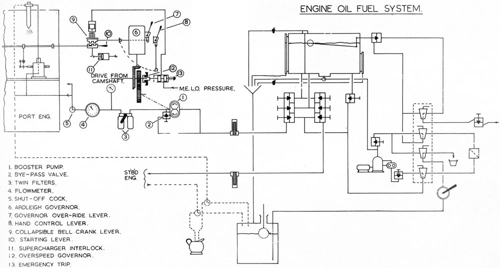
Fuel is admitted to the system from the subsequent line, via a valve (operated by a float in the gravity tank), and a centrifuge. Both or either of these can be by-passed if necessary. The outlet from the gravity tank is led to a 6-valve chest where it can be fed to either the engines, or to the snap tank. The valve chest can also be used to by-pass the gravity tank enabling fuel to be supplied direct from the centrifuge discharge, should the booster pump fail.
Fuel passes to the engine suction rail via the following fittings:
a. Non-return check valve
b. Booster pump
c. Twin filter
d. Flowmeter
e. Shut-off cock
(a) and (b) can be by-passed.
Injector leak-offs and gravity tank drains are led to a drain tank which can be emptied by a hand pump. A cock is fitted on the leak-off line to allow measurement for trial purposes.
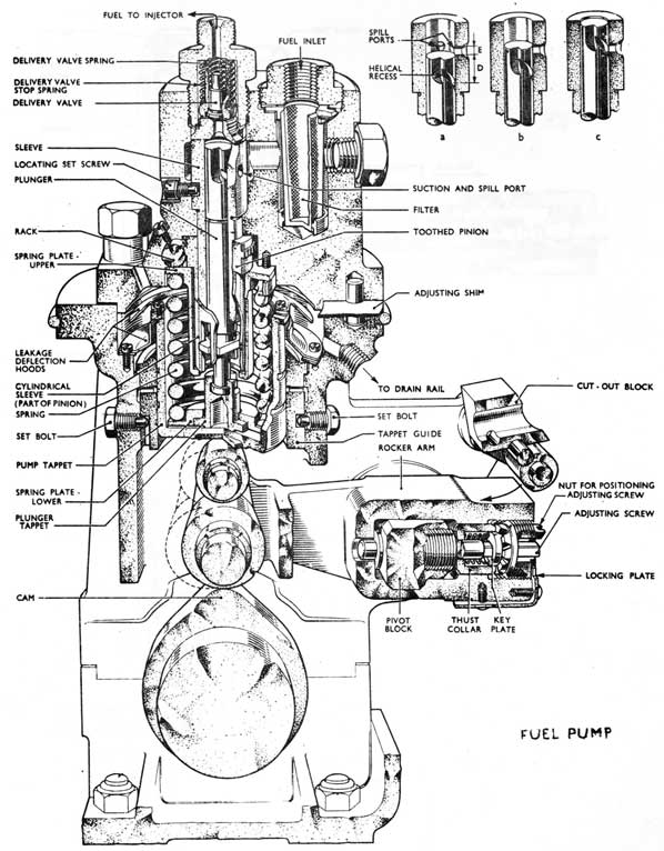
(14) FUEL PUMPS
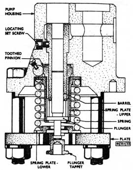
The 16 pumps are of Chatham type with Bryce elements. Each is operated by a cam on the engine camshaft, return motion being effected by a heavy spring contained within the pump tappet. Two shell bearings for the camshaft are housed in the lower part of the pump.
In fig. (a), (b) and (c) show the pump plunger at three positions on its upward stroke. As the plunger rises from positions (a) to (b) fuel will be discharged through the two suction ports until the upper edge of the plunger reaches the upper edge of the suction ports (position b).
At this point the fuel in the barrel is imprisoned and further upward motion of the plunger compresses the fuel until it lifts the spring-loaded discharge valve and passes at high pressure to the injector. Further upward travel of the plunger increases the pressure to a point at which it overcomes the resistance of the spring-loaded valve in the injector and fuel is injected into the cylinder.
13-56
13-57
The point at which fuel ceases to be supplied is governed by the incidence of the upper edge of the helical recess in the plunger. Once this edge reaches the lower edge of the spill port, the fuel pressure will be instantly released through this port (position c).
Although two ports are provided in the barrel only one governs the point at which fuel ceases to be discharged, the purpose of the other being to ensure complete charging of the barrel with fuel.
It will be apparent that the 'mechanical' stroke of the pump remains unaltered, but the 'effective stroke will be subject to the relative positions of the 'upper edge of the spill port and the upper edge of the helical recess. In the Fig. the effective stroke is D minus E.
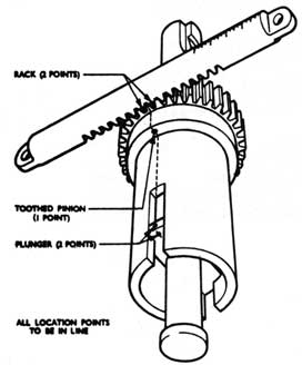
Pump output is dependent upon the radial position of the plunger which can be varied by means of a control sleeve. This sleeve is slotted at the lower end to engage a rectangular flange formed near the lower end of the plunger, and has a pinion machined on the upper end to engage a rack. All racks are connected to a common control shaft.
Discharge Valve
The spring-loaded discharge valve is flat-seated and works in a valve guide also spring-loaded. As the pump plunger rises the initial pressure lifts the valve until it contacts a shoulder inside the guide. Resulting from this the available area subject to fuel pressure is increased and further upward movement of the valve is sharper. The fuel pressure in the chamber outside the valve is also sharply increased.
Similarly, on the return stroke of the plunger a sharp decrease in the fuel pressure is obtained. The sharp increase and decrease in the fuel pressure results in a 'snap' action of the injector valve, thus producing 'anti-dribble conditions at the injector orifice.
Timing Gear
Fitted to each pump to enable the point of fuel injection to be adjusted as necessary. Consists of a rocker arm pivoted at one end on a block which is free to oscillate
13-58
Fuel Pump
13-59
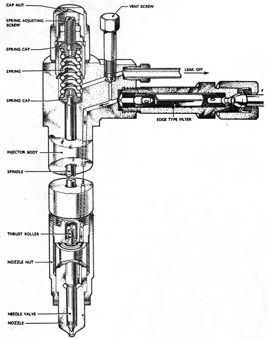
FUEL INJECTOR
13-60
13-61
on two bearings. The other end is forked to carry two rollers one of which bears on the fuel cam and the other on the pump tappet. The pivot block is threaded internally to receive an adjusting screw, which is positioned axially by a positioning nut screwed to the rocker arm. The outer end of the screw is squared to take a 'T' shaped adjusting handle, and the screw can be retained in any of eight positions by a spring-loaded key-plate which engages in 'V' shaped slots on the underside of the positioning nut. Adjustment is made by compressing the spring until the key-plate is clear and then turning the adjusting screw as necessary. This constrains the rocker arm to move laterally.
Note: The pivot block has no lateral movement but only oscillates.
Variations of Timing
One turn of adjusting screw = plus or minus 4° (on crank angle basis).
The maximum variation obtainable is 6° either side of mid position.
Note: The pump must be cut-out to alter timing.
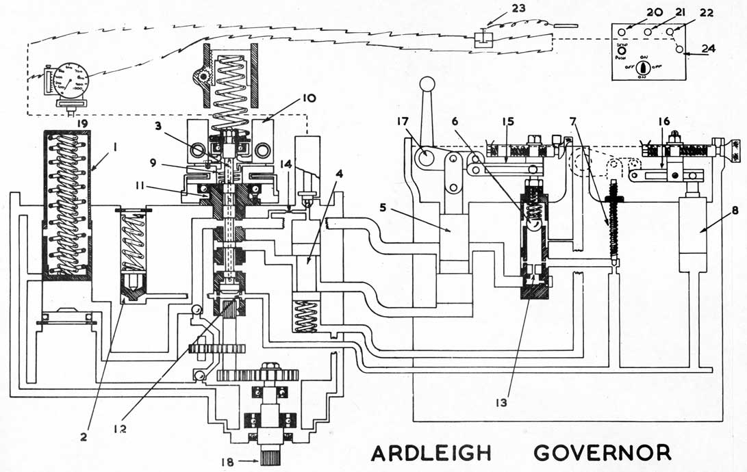
(15) Ardliegh Governor
The Ardleigh governor is of the centrifugal flyweight type and operates through a hydraulic servo-mechanism, the oil reservoir, gear type pump and two spring-loaded accumulators for which, are contained in the governor casing. The flyweights are driven from the right hand bank camshaft through gearing, a rotor sleeve and a rotor spring, the latter assisting in dampening out the cyclic variations in the drive.
The power piston of differential area type is linked to the fuel pump control shaft. It is also linked to the stabilising feedback piston and the droop control valve, these links being adjustable so that the amount of stabilising feedback and/or droop can be varied as necessary. In the S/M application of the governor the setting of the droop control valve is kept constant. A droop restrictor allows high pressure oil to pass to the feedback system, and an adjustable restrictor, in the form of a screw, controls the flow. Any excess pressure is relieved to drain through the droop control ball valve.
13-62
1 PRESSURE ACCUMULATOR
2 FEEDBACK PISTON
3 PILOT VALVE
4 SOLENOID SHUT DOWN VALVE
5 POWER PISTON
6 DROOP CONTROL BALL VALVE
7 FEEDBACK ADJUSTABLE RESTRICTOR
8 STABILISING FEEDBACK PISTON
9 ROTOR DRIVE SPRING
10 FLYWEIGHTS
11. ROTOR SLEEVE
12 RESTRICTOR 'FOR PILOT VALVE FEEDBACK
13 RESTRICTOR FOR DROOP VALVE
14 RESTRICTOR TO SHUT DOWN VALVE
15 DROOP LEVER
16 STABILISING FEEDBACK LEVER
17 OUTPUT SHAFT
18 DRIVE FROM R.H.B. CAMSHAFT
19 DRIVE FROM L.H.B. CAMSHAFT
20 GREEN LAMP ON WHEN L.O. PRESS. ABOVE 15 P.S.I.
21 GREEN LAMP ON WHEN L.O. TEMP BELOW 170 deg F
22 GREEN LAMP ON WHEN SOLENOID IS ENERGISED
23 SHUT DOWN DIST WATER REACHES 200 deg F
24 SOLENOID RESET SWITCH
13-63
Shut down is effected by means of a solenoid-operated ball valve, which, when the solenoid is de-energised directs the pressure oil above the shut-down valve to drain, resulting in the shut-down valve being moved upwards by its spring and so opening the underside of the power piston to drain. This allows the power piston to be moved downwards by the pressure oil above it and so move the fuel pump control shaft.
Operation
Load Increase. Any increase in load will cause
the speed of the engine to drop and the flyweights will
move inwards because the force of the speeder spring will
be greater than the force exerted by the flyweights plus
the pressure in the feedback system. The pilot valve will
move downwards, permitting high pressure oil to pass to
the underside of the power piston which will therefore be
moved upwards to increase the fuel supply to the engine.
Simultaneously the stabilising feedback piston will be
moved downwards by the links and the oil on its underside
will be displaced in the feedback system causing the feedback
piston to rise against its spring action, thus increasing
the pressure in the system. This increased pressure acting
on the bottom of the pilot valve plus the flyweight force
tends to raise the pilot valve to cut off the flow of pressure
oil to the underside of the piston.
Due to increased output of the fuel pumps, the drop in speed will first be checked, then increased to the original rev/min. This will cause force of flyweights to return to its original value, but as this occurs, oil pressure in the feedback system also returns to its original value through the adjustable restrictor and the droop ball valve, thereby keeping the pilot valve in a state of balance, in its neutral position.
Load Decrease. As the load is decreased the speed of the engine will rise causing the flyweights to move outwards and lift the pilot valve to release the control oil trapped below the power piston. The high pressure oil acting on the upper surfaces of the power piston will force it down and so decrease the fuel supply. Simultaneously the stabilising feedback piston will rise causing the pressure in the feedback system to drop and this will tend to bring the pilot valve down to close the control oil port.
13-64
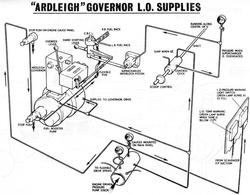
Ardleigh Governor L.O. Supplies
13-65
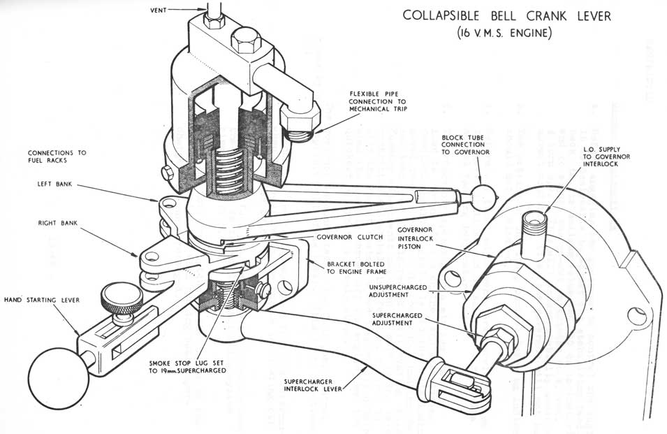
Collapsible Bell Crank Lever
(16 V.M.S. Engine)
13-66
General Instructions
a. Before engaging the governor to control the engine it is desirable to adjust the stabilising feedback to its maximum value (No. 10 on indicator), and to adjust the re-set restrictor to approx. 1/2 turn open. This will ensure stability under all normal conditions (i.e. the governor will not hunt).
b. The setting of the droop control (zero on indicator) should not be altered.
c. Before any final adjustments are carried out on the governor it should be allowed to reach its normal running temperature.
d. To reduce overspeeding to a minimum when the load is thrown off the engine, the stabilising feedback should be gradually decreased (indicator moved towards zero) until continuous hunting occurs and then gradually increased until hunting ceases. Further adjustments may then be made to the re-set restrictor and stabilising feedback control to give the lowest maximum speed temporarily obtained when the load is thrown off the engine, and the quickest return to a steady state.
The governor is connected to the fuel pump control racks by a Collapsible Bell Crank Lever. This lever functions to:
a. Disconnect the fuel pump racks from the governor when the pressure in the engine lubricating oil system falls below 10 p.s.i.
b. Connect the fuel pump racks to the governor when the pressure in the engine lubricating system rises above 10 p.s.i.
c. Limit the fuel consumption of the engine to the maximum permissible when running both supercharged and unsupercharged.
13-67
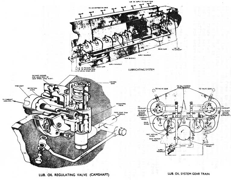
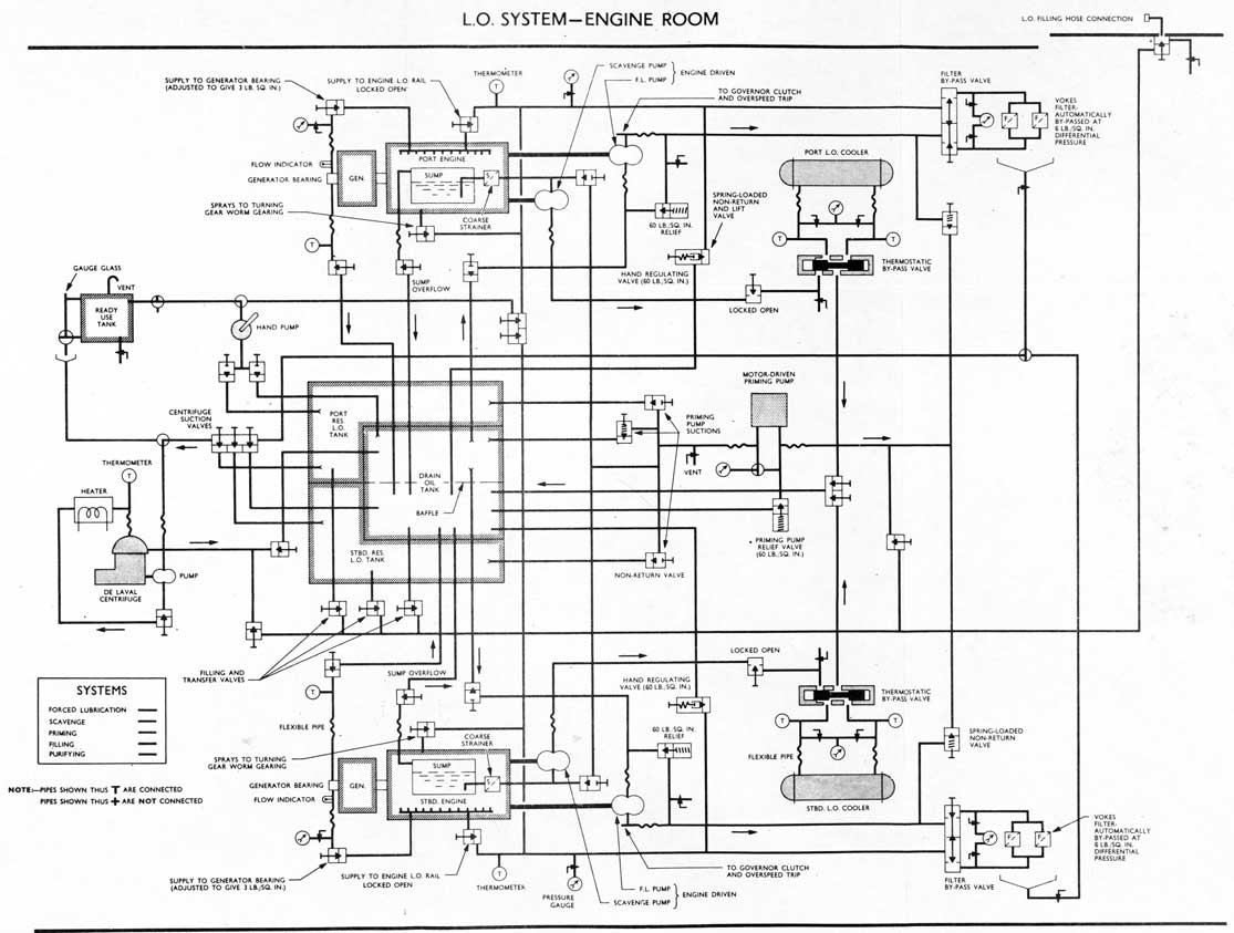
(16) LUBRICATING OIL SYSTEM
(a) General
Clean reserve lubricating oil is stored in two tanks constructed beneath the engine beds. Tank capacities - port 2603 gal. starboard 2200 gal. 011 in these tanks is used to replenish the D.O.T. (capacity 780 gal.), built between the reserve tanks.
The D.O.T. functions as an oil reservoir common to both engines. It is split into port end starboard sections by a baffle which has a number of limber holes cut through it.
Not oil drained from the engine bearings collects in a sump from which it is extracted by an engine-driven scavenge pump and discharged to the starboard side of the D.O.T. via an oil cooler. Oil then flows through the limber holes into the port side of the tank where it provides suction to the engine-driven pressure pump. The pressure pump supplies the engine L.O. manifold via a parallel flow twin Yokes filter. One branch from the manifold supplies the generator end bearing which drains direct to the D.O.T.
Clean oil for general purposes is stored in a ready-use tank which is filled by a hand pump from the port reserve tank. This pump can also be used to prime the engine from the D.O.T. or P.R.L.O. tank.
A motor-driven priming pump provides pre-starting circulation of oil. It can be used to discharge oil through the filling line, and has a suction from all tanks.
A centrifuge is provided which can suck from or discharge to any selected tank. All tanks have a dip rod and a combined vent and blow.
Oil is embarked through a portable gooseneck No. 2 connection on the casing.
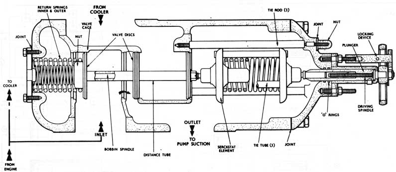
(b) Scavenge System. Warm oil from the engine sump is extracted by an engine-driven gear type scavenge pump. The pump discharges to a Serck cooler via a thermostatically controlled by-pass valve which is set to maintain a temperature of 145° at the engine inlet. The by-pass valve (Serckstat) is set by the manufacturer and should not be altered.
13-68
13-69
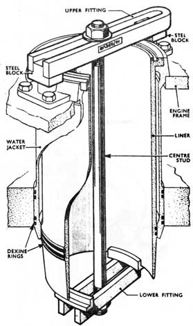
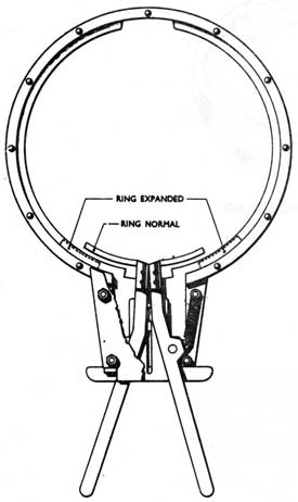
The oil cooler is of conventional Serck type consisting of a straight tube nest supported between two tube plates. One tube plate is free to move to allow for the expansion of the tubes. Oil and water sealing at this end is obtained by fitting an expansion ring with a rubber ring on each side of it, around the tube plate and clamping the three rings between the adjacent flanges of the cylinder and the end box. On assembly the rubber rings are compressed only sufficiently to withstand the water pressure tests of the oil and water spaces.
Oil flows around the outside of the tubes in a single pass, and baffle plates are fitted to increase the effective length of the cooling pass. The water flows through the tubes in a two pass arrangement. Vent plugs are provided for the oil and water spaces.
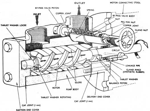
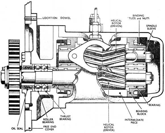
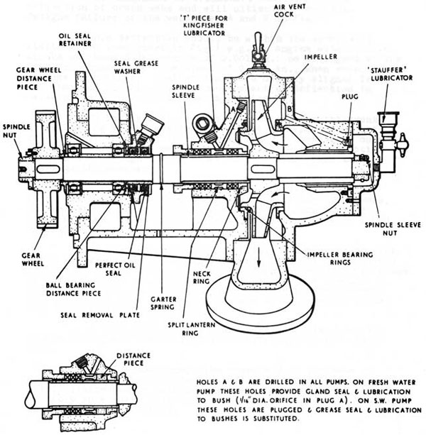
Pumps. The scavenge and pressure pumps are similar in design differing only in dimensions. They are driven from the spring wheel drive at the free end of the engine. The pumps are of the Drysdale Horzoil type, the two rotors (driver and driven) of each consisting of a pair of opposite handed double helical gearwheels. The rotors are keyed to the shafts and work in an intermediate piece which ha s suction and delivery ports cut in it. The shafts are supported in whitemetal lined bearing bushes and the whole assembly is located axially by a ball thrust bearing fitted to the driving shaft.
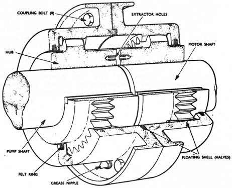
The priming pump, of Imo type, is driven through a Crofts type coupling by an electric motor, the armature shaft of which is extended at the other end to form the driving spindle of the engine distilled water cooling pump. A hand-operated, spring-loaded by-pass valve normally set to 60 p.s.i. is fitted across the suction and delivery passages in the pump body.
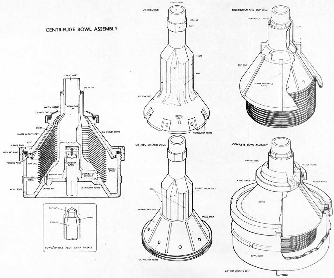
(17) PURIFIER
If a liquid is allowed to settle in a tank, the heavy particles suspended in the liquid will fall to the bottom. If the liquid is subjected to centrifugal force many times greater than gravity, this separation will be accelerated and rendered more complete.
13-70
IMO LUB OIL PRIMING PUMP
CROFT'S COUPLING
13-71
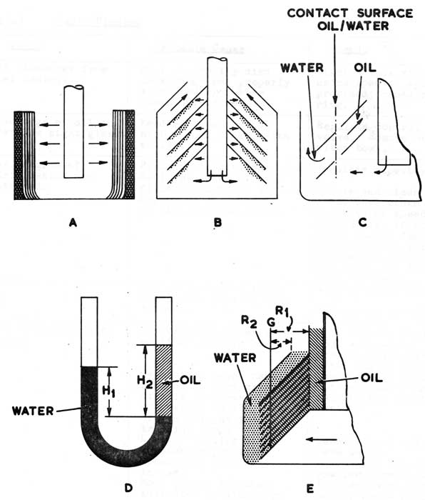
Fig. a shows a bowl containing a liquid revolving at high speed around a vertical shaft. Due to the action of centrifugal force, the suspended particles will settle out rapidly at right angles to the axis of rotation, i.e. towards the periphery of the bowl.
The degree of separation obtainable depends on the velocity of the particles in the liquid and on the distance they have to travel before being separated.
The introduction of conical discs over the vertical
shaft enabled a small bowl to be used run at reasonable
speed, this gave a high efficiency and output. Fig. b shows
the effect of using these discs. Liquid is supplied through
the central tube and is distributed between the discs, which
are fitted very close together and divided the liquid into
a number of thin layers. Separation takes place between the discs,
the heavy particles moving towards the periphery of the bowl
under the action of centrifugal force. They soon reach the
underside of a disc and so are separated from the stream of
liquid.
Fig. c shows an enlarged section of the bowl, containing conical discs used for the separation of oil, dirt and water. Water and dirt being heavier move towards the periphery of the bowl following the underside of the discs. The water and the discs form a seal through which the oil cannot escape. As more liquid is supplied the oil will be forced to move towards the centre of the bowl against the action of centrifugal force. The mixture of oil, water and dirt passes down the distributor tube to the distributor chamber and enters the set of discs through the distributor ports. Here separation starts, water and dirt moving towards the sludge space in the periphery of the bowl, and the oil towards the centre. The water passes through the water outlet ports, which are grooves formed between the top disc and the cover. The purified oil passes through the oil outlet ports to the oil outlet.
Fig. d shows a 'U' tube containing a mixture of oil and water. These two lipids will settle out, the relation between the levels 'hl' and 'h2' above the line of contact 'G' adjusting itself to correspond to the relation between the S.Gs. of the two liquids as follows: -
h1/h2 = S.G.2/S.G.1.
13-72
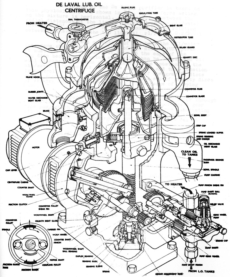
De Laval Lub. Oil
Centrifuge
13-73
The action of the De Laval purifier is based on this physical law. As shown in Fig. e, the force acting on the mixture is horizontal. The relation between the radial distances of the liquid outlets from the oil/water interface 'G', 'r1' and 'r2' corresponds to the relation between the S.Gs. of the two liquids: rl/r2 S.G.2/S.G.1
For correct operation of the bowl the oil/water interface should be in the line of the distributor ports. It must not reach further out than to the edge of the top disc because the water seal will then be broken and oil will discharge from the water outlet. The location of the oil/water interface is therefore important and this location is controlled by the internal diameter of the gravity discs used. Each purifier is provided with a set of gravity discs of varying internal diameters to cover a range of varying S.Gs.
The purifier is driven by an electric motor through a friction clutch and worm gearing. It incorporates a gear type pump which can suck from either of the three lubricating oil tanks and discharges via an oil heater to the distributor tube. Purified oil discharged from the centrifuge can be directed to either of the three oil tanks.
Operational Data
Speed of bowl
7000 rev/min.
Speed of wormwheel
1450 rev/min.
Speed of counter
77-83 rev/min.
Capacity
210 gal/min.
Temperature of oil for purification
160°F.
Acceleration time for bowl
2-3 min.
Mountings (centrifuge and motor)
250 lb. type 'L'
13-74
PRINCIPLE OF CENTRIFUGAL SEPARATION
13-75
(17a) Fault Finding
Fault
Probable Cause
Remedy
Oil discharge from bowl casing.
Bowl or gravity disc lock rings not properly tightened or rubber rings defective.
Tighten lock ring using special spanner provided; renew rubber ring.
Discharge of oil in overflow sight glass.
Feeding capacity too high. Bowl choked with solids.
Regulate control valve. Remove and clean bowl.
Max. degree of purification not obtained.
Feeding capacity too high. Sediment space of bowl filled with solid matter. Separator not running at its designed speed.
Regulate capacity.
Remove and clean bowl. Check bowl brake clear. Check motor speed with tachometer, if correct: check clutch for oil, clutch blocks for freedom on their spindles, and Ferodo pads for wear.
Oil at incorrect temp. Wrong size gravity disc in use.
Adjust heater switches.
Select and fit new disc.
Oil discharges with water.
Insufficient quantity of sealing water in bowl.
Separating temp. has changed so that gravity disc in use does not correspond to the S.G. of the oil, at the treating temp.
Loss of sealing water through evaporation. Wrong size S.G. disc in use.
Bowl joints leaking; indicated by discharge from bowl casing drain.
Shut off oil feed and pour warm water gradually through water filler plug. Temp. of oil should not be allowed to fall to any great extent.
Re-seal bowl with warm water.
Select and fit next smaller size disc. Tighten locking rings and/or renew rubber rings as necessary.
13-76
Fault
Probable Cause
Remedy
Centrifuge does not function satisfactory.
Bowl has been wrongly assembled.
Solids have settled unevenly in bowl.
Components of bowl damaged or corroded.
Strip bowl and re--assemble.
Clean bowl thoroughly before attempting to re-start. Fit spare bow.
Gear pump does not function correctly.
Taper pin securing pinion to wormwheel shaft sheared. Relief valve leaking or incorrectly set. End clearance of rotors too great.
Examine gears, fit new taper pin.
Refit and reset to 10 lb/sq.in. Adjust clearance to 0.0015 in.
(17b) Sea Water Contamination of Engine Lubricating Oil
The possibility of contamination of the main engine lubricating oil by salt water cannot be entirely eliminated in S/Ms. Contamination can, however, be checked by frequent test of the oil, end the resulting damage (corrosion, bearing failures, etc.) can be obviated by prompt treatment.
The importance of early discovery of contamination and the correct operation and maintenance of lub. oil separators cannot be too highly stressed.
The falling off in performance of the separator is most frequently due to one or more of following factors:
a. An unsuitable gravity disc.
b. Oil temperature too low.
c. Presence of emulsion in the oil.
The most frequent cause is (b). The oil should be heated to 160°F. in normal use, and up to 190°F. for short periods, of up to 8 hours, when excessive water contamination is present. The S.G. of the oil in use is to be checked weekly at 160°F. and 190°F. and the results noted. (The S.G. correction fareset is 0.0004 per °F change of temperature).
13-77
Should contamination be discovered and subsequent to the action taken below, a full report should be forwarded to CANCOMSUBRON ONE This report should include details of the cause of contamination, action taken, and also the manner in which the separator was operated during the period of contamination, e.g. times of starting and stopping, routine cleaning, amount of sludge removed from the bowl and temperature input, both before and during remedial action.
In order that the instruction below can be fully implemented, separate action is being taken to:
a. Provide means of drainage for any pocket in the lub. oil system that is not already provided with drainage.
b. Provide where possible larger heaters for the separators.
The treatment has been divided below into two sections, in harbour and at sea.
( 17c) Contamination Limits and Treatment - In Harbour
Each week a sample should be drawn off the D.O.T. whilst the engines are running, using the hand pump, and the following tests made:
a. Water content using the speedy moisture tester.
b. Specific gravity test.
c. Salinity test using the Boiler Feed Water Test Set.
Satisfactory Oil Condition
If tests in para. 7 show a water content not greater than 1% and/or salinity not greater than 10 grain/gal., then the oil may be considered satisfactory provided:
a. Engine lub. oil consumption, as shown by make up of the D.O.T., is not less than 2% of fuel consumption (i.e. there is sufficient additive replenishment to deal with this degree of contamination).
b. The separator is operating efficiently.
13-78
c. Any source of contamination is investigated and eliminated or controlled.
d. Known pockets or system low points, e.g. filters, coolers, pumps, pipe loops, etc., are checked clear of water at regular intervals.
Moderate Contamination
If tests in pars 7 show a water content between 1% and 5A and/or salinity between 10 grain/gal. and 30 grain/gal. the following action should be taken as soon as possible:
a. Stop engines and check all known pockets and filters clear of water. Repeat at intervals.
b. Ascertain sources of contamination and eliminate or control them.
c. Run the purifier continuously, preferably with the engine running at about half full power loading, at a throughput temperature of 190°F. until contamination is down to an acceptable limit.
d. If with the contamination sources located and checked, there is no significant improvement, particularly of salinity, then action should be taken as below.
Gross Contamination
If the tests in pare 7 show a water content above 5% and/or salinity above 30 grain/gal. action should be taken as below:
Stage 1
a. Drain down the lub. oil system, clear all pockets and filters, remove felt filters, insert temporary filters, discharge and mop out D.O.T. using butning or rags.
b. Ascertain and eliminate or control the source of contamination.
13-79
c. Charge the D.O.T. with the minimum amount of clean oil, to maintain adequate circulation.
d. Switch on D.O.T. heaters, where fitted, to maintain a temperature of 120°F. in the D.O.T., end circulate the oil through the engines and system for 1 hour, using the priming pump, with the engine turning up and the separator running with a throughput temperature of 190°F.
e. Draw off a sample from the D.O.T. using the hand pump and carry out test as in para 7(a), 7(b) and 7(c).
f. If the tests show that the oil is still contaminated repeat (a), (c) and (d) above as many times as necessary until the results show a 'satisfactory oil condition', pare 8.
Stage 2
g. When (f) above has been completed, drain down the system, clear pockets, wipe out D.O.T., remove temporary filters and replace the felt filters. charge the D.O.T. with 400-500 gals. of clean oil. Circulate for 4 hrs. with the engine running at about 2/5 to 3/5 full power and the separator running at 190°F. throughout temperature. Check water content and salinity on completion.
h. Top up D.O.T. to working level.
j. Revert to normal operating conditions.
Treatment at Sea
Each week at sea the following test is to be carried out:
A sample of oil drawn from the D.O.T. by the
hand pump is to be diluted with 100 times its
volume of pure distilled water. The addition
of silver nitrate will just show a cloud if
the salinity of the D.O.T. sample is 10 grain/gal.
13-80
Should contamination exist it is important to take action as quickly as possible. Obviously the positive action is limited. The following should be carried out:
a. Investigate source of contamination and eliminate or control it.
b. Stop engines. Drain down system, clear pockets and filters. On completion top up D.O.T. to maximum working level.
c. Ensure separator is working correctly. Run separator continuously at throughput temperature of 190°F.
d. If possible the engines should then be run at about 1/2 full power loading whilst the salt contamination remains above 10 grain/gal.
e. On return to harbour commence full treatment immediately.
NOTE: The Silver Nitrate test used with detergent oils is known to be unsatisfactory. 'Cloudiness' or 'Turbidity' is detectable in contaminated oil samples, when treated as detailed. A slight cloud in a sample from the D.O.T. should therefore be treated with reserve. A comparison test with a known clear sample will be the best guide. If a doubt exists then every effort should be made to obtain a check using the Boiler Feed Water Test Equipment at the earliest possible opportunity. (This equipment too is suspect when used with detergent oils, but no superior laymans' equipment is yet available).
13-81
(18) INSTRUCTIONS FOR FLUSHING A.S.R.1. 16 VMS SUBMARINE DIESEL ENGINE LUBRICATING Oil, SYSTEMS
The procedure detailed below is to be adopted to ensure the cleanliness of the lubricating oil systems. Once started the process is to be progressively continued until both engine systems and their associated external systems have been cleaned and flushed through.
Only one engine system is to be flushed through at a time. The Lub. Oil Purifier is to be run continuously on the D.O.T. during the flushing process, and the Priming Pump pressure is to be maintained at the maximum available. Temperature of the oil is to be maintained as near as possible to, but not exceeding, 160°F.
a. Clean engine sumps including scavenge pump suction boxes and strainers.
b. Clean Filter bodies and check Vokes Filter elements in place.
c. Check suction pipes from D.O.T. to Priming Pump and Engine Driven Lubricating Oil Pumps clean. See Note (v).
d. Clean D.O.T. and R.L.O. tanks. On completion, and immediately before closing up, these are to be inspected.
e. Fill D.O.T. with 600 gallons of 3 GP , 903b grade 30 (or oil normally used) using 100 mesh gauze during filling. Check pipe length external to hull filling valve clear of water and dirt.
f. Check Filter by-pass valves for tightness.
g. Check calibration of Lub. Oil Filter differential gauges.
NOTE: All cleaning is to be done with lint free cloth.
Shut and lock the supply valve to the engine L.O. Bail. Break the supply pipe to this valve at the nearest point to it and connect the supply pipe to the Scavenge Pump discharge flexible pipe using a temporary flexible pipe. This isolates the engine system during initial flushing of the external system. The operation is to be carried out with minimum delay and with careful attention to ensuring that no dirt enters the system.
13-82
Fit 100 mesh gauzes in the suction of the Lubricating Oil Priming Pump, the inlet to the Filter, at the flexible pipe Scavenge Pump discharge to the Lub Oil Cooler and in the return line at the inlet to the D.O.T. Where fitted in a pipe of greater bore than 1 1/2" the gauzes should be backed by a perforated plate of open area. The gauzes are to be examined and cleaned at frequent intervals during the flushing procedure. Check bypass valve "open" to filter. All sections of the external system are then to be flushed through by means of the Priming Pump, blanks and flexible pipes being used where necessary to facilitate flushing of pipe lengths not catered for by arrangements detailed in paragraph 4. Particular care should be taken with the section through which oil flows when the Filter is bypassed. Flushing of each section is to continue until no further foreign matter is collected by the 100 mesh gauze and the D.O.T. inlet or for four hours whichever is the longer. On completion check the Filter bypass valve
open" to Filter.
On completion of the process in paragraph above unblank the external system, and, after flushing through the previously blanked dead end, reconnect it to the engine supply rail. Open crankcase doors and disconnect all main bearing lubricating oil supply pipes at the bearing end. Shut the camshaft supply regulating valves and disconnect the supply pipes to the valves controlling the supply of
oil to the valve gear. Fit 100 mesh gauze over the ends of
the open pipe connections. Circulate hot oil for 2 hours or until gauzes show clean oil to be circulating, whichever period is the longer, with Purifier and heaters in use.
On completion reconnect bearing supply pipes and valve gear supply pipes. Disconnect the oil supply
connections to each valve lever bracket and camshaft bearing and flush through with hot oil on each bank of cylinders in turn.
Keeping oil temperature as near 160°F. as possible and with filters and heaters in use, flush through complete engine lubricating oil system for 6 hours using the Priming Pump. The purifier is to be running continuously on the D.O.T. during this process and turn the engine by hand for 1/2 revolution every 15 minutes.
13-83
On completion remove and examine all gauzes. Run the engine at no-load idling speed for 5 minutes and then at no-load full speed for a further 10 minutes.
Allow engine to drain. Pump out sumps and D.O.T. discharging flushing oil as dirty waste. Clean sumps and D.O.T. and refill with 600 gallons fresh 3GP903b. Thoroughly clean Filter bodies and renew Filter elements. Examine and clean gauges and serckstat elements.
NOTES:
(1) Particular care is to be taken that the
differential pressure of the lubricating oil filter does not exceed 6 p.s.i. during the flushing procedure, as bypassing of the filter will occur above this figure. This has been known to occur on initial firing due to sudden choking.
(ii) Purifiers are to be cleaned before commencing the procedure laid down in each of paragraphs
5, 6, 7, 8 and 9.
(iii) Particular care is to be taken to ensure that lubricating oil purifiers are run during the whole of the generator trials and during any preliminary running and trials. Purifiers are to be opened up on completion of any running for examination of centrifuged solid matter. Purifiers are to be fully used and cleaned frequently during Sea Trials and during intervals when machinery is not running.
(iv) The flushing of the external systems should only be undertaken when the degree of disturbance during a refit or major repairs warrants it. The flushing of the engine lubricating oil systems need only be done when the degree of disturbance of the engine warrants it i.e. not normally at top overhauls.
(v) Cleaning of suction pipes from D.O.T. to the Priming Pump and Engine driven lubricating oil pump, and of other pipes associated with the lubricating oil system but not specifically covered by the above instructions, is only to be undertaken if these pipes have actually been disturbed during the repairs or refit. The refitting authority has discretion in deciding the amount of work undertaken in this respect.
13-84
CENTRIFUGE BOWL ASSEMBLY
13-85
FORCED LUBRICATION PUMP
13-86
L.O. SYSTEM-ENGINE ROOM
13-87
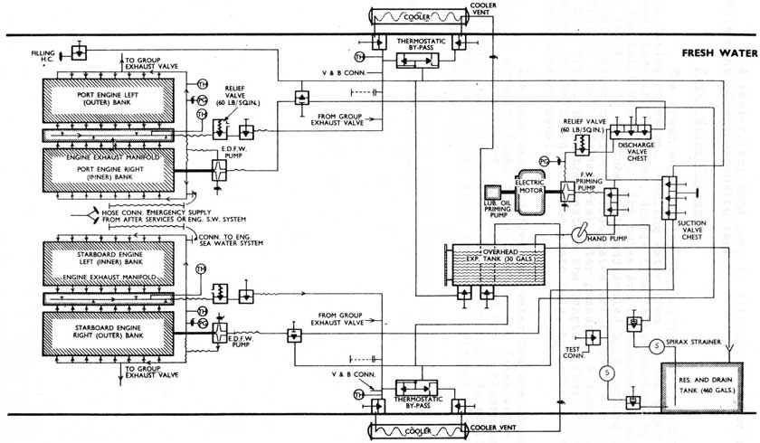
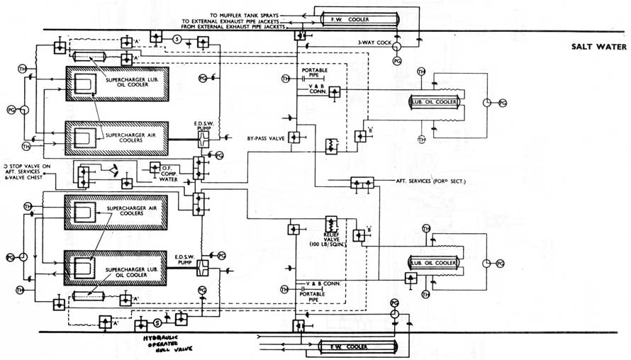
(19) ENGINE COALING WATER SYSTEMS
Two systems are provided, fresh water and sea water, each being supplied by an engine driven centrifugal pump driven by a spring drive wheel bolted to the crankshaft damper. Part of each system is outside the pressure hull, and is consequently tested to 400 p.s.i. Internal systems are tested to 150 p.s.i.
Sea Water System
Water is admitted via a hydraulically-operated hull valve, a strainer and an intermediate valve to the pump suction. The pump discharge is led to a valve chest which supplies:
a. O.F. compensating water
b. Supercharger air coolers
c. Lubricating oil coolers
d. Fresh water coolers, external exhaust pipe jackets and muffler tank sprays.
e. Godfrey (centrifugal) supercharger oil coolers.
The water flow through the L.O. cooler is controlled by the setting of the cooler by-pass valve. Under normal conditions the supply valve to the air coolers is wide open, allowing a flow of 8000 gal/hour to the coolers. As the pump output is 16,500 gal/hour, the remainder is available for L.O. cooling. The outlets from the air coolers and the L.O. coolers are led outboard via a S.D.N.R. valve to the fresh water cooler and remaining external system.
Fresh Water System
Circulation is maintained through a closed circuit by the fresh water pump. The pump sucks from the fresh water cooler via a thermostatic by-pass valve, and discharges into the engine circulating water supply manifold. From this manifold water is led to the liners, heads, exhaust bends and exhaust manifold and is collected in the outlet manifold. From the outlet manifold water is led to the cooler inlet.
An expansion tank is fitted to keep the system full. Ethelyne Glycol is added to the water in the system.
A priming pump is provided which is driven by the same motor as the L.O. priming pump. This pump can be used for the following purposes:
a. Filling the system
b. Circulating prior to starting and after stopping the engine.
c. Emptying the system and reserve tank.
13-88
Fresh Water
13-89
A semi-rotary hand pump is also provided for replenishment of the expansion tank.
Fresh Water Cooler
The fresh water cooler is constructed to withstand full diving pressure. Cooling water from the sea water service
passes through the tubes, double flow being obtained by division
of the inlet water box. The tubes are of aluminum bronze and are rolled into the tube plate and sealed by a coating of lead nickel binding metal. Baffle plates are fitted to extend the effective length of the fresh water passage. A dummy tube wall is also fitted to further extend the length. These tubes are secured to the fixed end tube plate only, by means of lead nickel binding metal.
The tube nest and free end water box are contained within a pressure tight casing in which the fresh water circulates. Expansion of tubes is allowed for by clearance between the tube nest assembly and the casing. No sealing arrangement is required since there is no passage for mixture of salt-fresh water.
In order to reduce corrosion effects, all studs are fitted with cap nuts.
13-90
SERCKSTAT FRESH WATER TEMPERATURE CONTROL VALVE
13-91
SALT WATER
13-92
ENGINE DRIVEN FRESH & SALT WATER PUMP
13-93
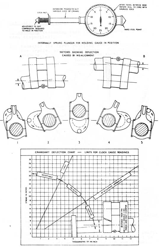
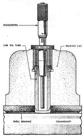
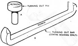
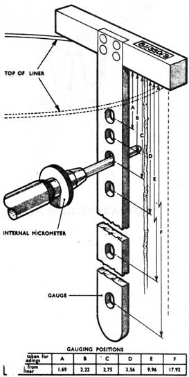
(20) MEASUREMENT OF WEB DEFLECTION AS AN INDICATION OF ALIGNMENT AND BEARING WEAR
Misalignment of crankshaft bearings causes deflection of crank webs and will ultimately result in fatigue failure of the webs (see A and B in Fig.).
This deflection should be within the acceptable limits given (see chart in Fig.) e.g. an engine with an 8 in. stroke may have a deflection of 0.001 in.: be religned at the first opportunity up to a limit of 0.003 in., when re-alignment becomes imperative. Smaller sizes are usually aligned from the wheel of the flywheel as measurement of deflection in between the crank webs may be impracticable.
While the most serious deflection in multi-crank units leading to fatigue fracture is to be expected at the driving end, where adjustment will first be necessary, care should be taken after making these to follow the deflection in sequence through to the other end, fitting spare main bearings if necessary.
The alignment of bearings at the driving end is to be checked by measuring the deflection of the crank webs, at the first opportunity after every 1,000 hours. Other crank webs are to be measured in the same manner every 2,000 hours.
In the case of angled or highly finished crank webs where the gauge may slip, a prick punch mark may be required; but, owing to the irregular contour of punch marks if the gauge is rotated about its axis to facilitate taking a reading, a false result may be obtained. It is better to use a mirror for those positions of the crank where it is possible to see the face of the gauge directly.
1 to 5 on Fig. show how readings can be taken for almost a complete revolution without dismantling the crank-head.
Should re-alignment be necessary in the case of generating sets, with a single bearing dynamo a reading within limits can be obtained by taking the weight of the armature on a screw jack before shifting the pedestal bearing to the required position.
13-94
CRANKSHAFT: ALIGNMENT AND MAINTENANCE
MEASUREMENT OF WEB DEFLECTION AS INDICATION
OF ALIGNMENT AND BEARING WEAR
13-95
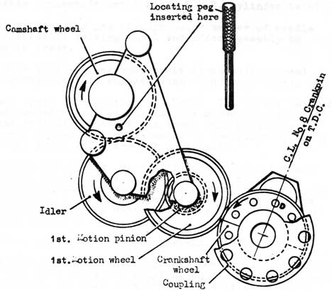
(21) CAMSHAFT DRIVING TRAIN
To assemble (assuming that the entire assembly has been dismantled).
1. Assemble the three rotating members, located in the cradle, of the R.H. train. The two free members, i.e., the 1st. motion wheel and pinion
KEY DIAGRAM - GEAR TRAIN ASSEMBLY
and the idler wheel can be freely assembled upon their appropriate spindles, the only requirement being that the 1st. motion wheel and pinion datum mark must coincide. The datum marks consist of a 'D' stamped on the side of the wheel adjacent to one of the bolt holes. Similarly the camshaft wheel is secured to its hub using identical datum marks on the side of the wheel and the flange of the hub.
2. When secured to the hub, fit wheel to stub shaft. This location is governed by a keyway fitted to the stub shaft and the bore of the wheel hub.
13-96
3. Fit crank wheel to crankshaft. This wheel is made in halves, the halves being bolted together and to a flange on the extension of the crankshaft. On the side of the wheel adjacent to one bolt hole is stamped 'D' and the wheel must be secured such that the 'D' is directly in line with the crank of No. 8 R.H.B. cylinder.
4. Rotate crankshaft until No. 8 R.H.B. cylinder is at T.D.C.
5. Insert locating peg through outer member of cradle and camshaft driving wheel and offer assembly to engine frame.
6. Remove locating peg and rotate first motion wheel slightly until it engages with crankshaft wheel.
7. Push train into position. (Note: The bottom half of the camshaft end bearing must be assembled with the gear train.) As the train moves into position, the wheels may move slightly owing to the slight angling of the teeth which are out on a helix.
8. Re-insert locating peg. If locating holes are not exactly in line, the training must be removed, a different tooth engaged on the crankshaft wheel and operations 5, 6 and 7 repeated. On completion the locating peg holes must be in line with No. 8 R.H.B. crank at T.D.C.
9. Secure cradle with stay bolts and spindle nuts.
10. Replace camshaft, ensuring that the marks on the flange of the stub shaft and coupling on the end of the camshaft coincide. In this case the marks will be 8 R.H.B.
The procedure for assembly of the left hand gear train follows identical lines, care being taken that the crankshaft remains in the same position as before, i.e. No. 8 R.H.B. at T.D.C.
Note: It is the responsibility of the senior rating present to see that the locating pegs are removed and stored in a safe place. Only the special pegs provided are to be used for timing operations.
13-97
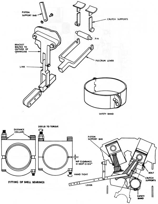
(24) ASSEMBLY OF ASRI CONNECTING ROD ASSEMBLIES
Prior to fitting in an engine, each connecting rod component is to be checked and assembled on a bench under clean conditions.
1. General Examination
a. Ensure that all items, including oilways, are completely clean and free from burrs.
b. Check that all components are identified so that they can subsequently be assembled in the same order.
If the bolts and nuts have not been identified, this should be done by marking (preferably by etching) with the engine No/cylinder line,
followed by a number from 1 to 4 (fork rod)/1 to 2 (blade rod) in an easily readable position, viz 6007/8/3 indicates that the bolt (or nut) is fitted in the No. 3 bolt hole of the fork connecting rod for No. 8 cylinder in engine No. 6007. Each bolt hole is to be marked 1 to 4 (fork end)/ 1 to 2 (blade rod).
c. Check that the 'free' length of each bolt (over gauging pallets) conforms with the decimal part of the length stamped on the side of the head of the bolt adjacent to the dowel locating slot. For the fork rod bolt, this should lie between .344 and .354 and for the blade rod bolt, between .125 and .135 Where the length is not indicated or the measured length differs from that indicated, the incorrect length marking is to be deleted and the actual length stamped on - over it.
d. Check that the parallelism and twist tolerances of small end to large end bores are within the limits on rods which have not been mated or where the small end bush is renewed (Repair Instruction No. 021 refers).
13-98
e. Try each 'Cleveloc' nut with its respective bolt. The self-locking feature should be sufficient to make it impossible to screw this portion of the nut down by hand over a standard bolt or screw thread gauge. Where the nut can be run down the full length of the bolt thread by hand, check the bolt thread by using a female gauge. If the bolt thread is satisfactory, reject the nut. If the bolt thread is unsatisfactory, reject the bolt.
f. Check that bearing shell locating dowels fitted in the Conn-rod large end bores do not fret the back of the bearing shell.
2. Assembly on a Bench
a. Assemble connecting rod components complete with large end bearing shells. Tighten nuts evenly until butt faces of the rods are just touching.
b. Zero the dial micrometer of gauge 81/355/81 to the free length of bolt No. 1 using stick micrometer and tighten the nut of No. 1 bolt until a stretch of approximately 0.014 in. is obtained. The stretch must be between 0.011 in. end 0.015 in.
Repeat for the remaining bolts, moving diagonally opposite in case of the fork rod, finally checking the stretched length of each bolt in turn.
c. With the nuts tightened to give the correct extension, mark, with a single vertical line, the centre of a conveniently placed nut face on each nut. Then mark a single radial line, coincident with the vertical line of the nut face, on the flat surface of the rod. This line is to run to the edge of the rod and a short vertical line to continue down the side of the rod. The lines must be scribed or etched on and not applied by chisel.
d. Check large end bearing shell 'nips' in normal manner, i.e. slacken nut(s) on one side and measure gap between butt faces. For fork rod shells, 'nips' should be between 0.004 and 0.014 in. and for blade rod shells, between 0.006 and 0.014 in.
e. Slacken remaining nut(s).
13-99
3. Assembly in an Engine
Assemble piston, connecting rod, large end bearing shells, etc, in the engine in the normal manner up to the point of tightening the 'Cleveloc' nuts. These should all be tightened evenly until the butt faces of the connecting rods are just touching and then tightened through another 38° (approx), when the lines on the nut land and on the rods should coincide. Check bolt extensions and, if necessary, adjust the bolt
stretch until it lies within the range 0.013 to 0.015 in.
NOTES:
1. As a rough guide the following approximate angular movements of the nuts are required to produce the associated bolt extensions, starting with the butt faces just touching:
Belt Extension (in)
Angular Movement of Nut (degrees)
Fork
Blade
Minimum extension
0.013
40
35
Required extension
0.014
43
38
Maximum acceptable
0.015
47
42
2. It must be realised that the locking properties of the 'Cleveloc' nut are only a secondary safeguard and, providing the nuts are tight and to give the correct bolt extension, no failures will occur. If the correct stretch is not applied, event with the locking properties of the nuts,
failures can and will occur.
13-100
MAIN BEARING WEAR DOWN GAUGE
MAIN BEARING EXTRACTOR TOOLS
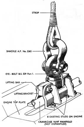
LIFTING BRACKET - ENGINE FRAMES
13-101
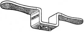
SPANNER FOR GRINDING VALVES
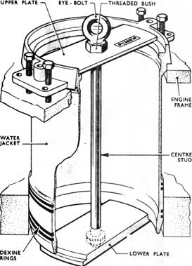
WATER JACKET EASING & LIFTING GEAR
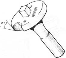
DUMMY GRINDING VALVE
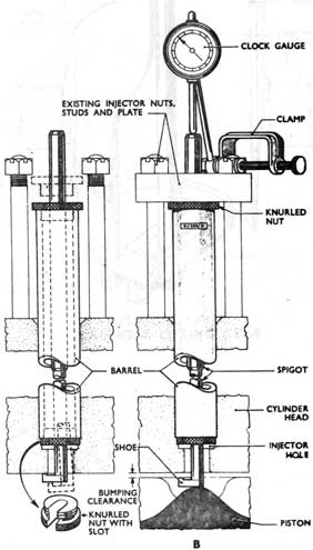
BUMPING CLEARANCE
13-102
GAUGING JIG FOR LINER
CYLINDER LINER EASING & LIFTING GEAR
13-103
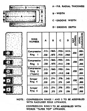
PISTON RING EXTRACTOR
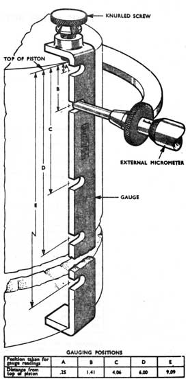
GAUGING JIG FOR PISTON
13-104
GAUGE RING FOR PISTON RINGS
PISTON RING CLEARANCES
13-105
A.S.R.I. PISTON WITHDRAWING GEAR
13-106
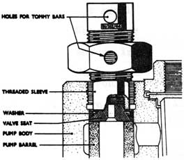
FUEL PUMP -
VALVE SEAT EXTRACTOR
FUEL PUMP ASSEMBLY GEAR
FUEL PUMP- ASSEMBLY DIAGRAM
13-107
(2) TO SPILL TEST A FUEL PUMP
1. Remove delivery valve and spring.
2. Fit small bore pipe provided on pump discharge.
3. Set pump rack at 18 mm.
4. Ensure independent timing gear in mid-position.
5. Fully open fuel supply from gravity tank; thoroughly vent suction side of pump.
6. Turn engine until pump plunger is at bottom of its stroke. Fuel will flow steadily from the small bore discharge pipe.
7. Turn engine slowly until flow ceases. This will indicate that the plunger has covered the spill ports.
8. Turn engine back until fuel flows and then repeat (7) above, stopping the engine at the exact point the flow ceases. This is the point of injection and can be read off in crankshaft degrees from the graduated scale on the damper rim. The reading should be between 26 1/2° and 27° B.T.D.C.
9. Once the point of injection has been determined the engine can be turned through the effective stroke of the pump and the point of cut-off read off when the fuel flows again. This should be 1/2 degree B.T.D.C.
A Chatham Gauge, which consists of a small bore glass tube fitted into a brass adaptor may be used instead of the pipe described in 2 above. If this is used it should be fitted in place of the vent screw of the injector.
13-108
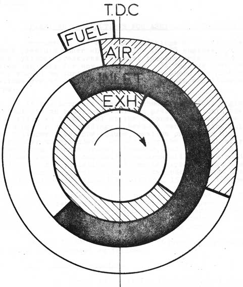
(24) TIMING DIAGRAM
FUEL VALVE
OPENS - 26 1/2° BEFORE T.D.C.
CLOSES- 1/2° BEFORE T.D.C.
AIR START VALVE
OPENS-10° B.T.D.C.
CLOSES-110° A.T.D.C.
PERIOD 120°
INLET VALVE
OPENS - 32° B.T.D.C.
CLOSES-46° A.B.D.C.
PERIOD 258°
EXHAUST VALVE
OPENS- 56° B.B.D.C.
CLOSES- 22° A.T.D.C.
PERIOD 258°
13-109
(25) OPERATING INSTRUCTIONS FOR ASR1-16 VMS ENGINES
Because of the varying conditions of Suction Depression and back pressure under which ASR1 - 16 VMS engines operate, maximum cylinder pressures, exhaust temperatures and fuel consumption can vary for any given load. It follows that the engines should be tuned under conditions where the number of variations are at a minimum, i.e. the surface condition at 920 rpm.
It has been the practice when tuning ASR1 engines to concentrate on equalizing maximum pressures within the limits laid down in BR 3601 at the expense of acceptable fuel pump, timings or rack readings. Because manufacturing tolerances affect cylinder clearance volume, maximum pressures will vary from cylinder to cylinder. In addition the Dies indicator instrument can be inaccurate. However, hot compression (individual fuel pump cut out) pressures will give a good indication of the variation that can be expected when comparing maximum pressures cylinder to cylinder. These hot compression pressures should be within ± 15 psi of the mean.
It is emphasized that the main criterion when tuning must be exhaust temperatures. High exhaust temperatures will result in burnt exhaust valves end increased maintenance
whereas the variation in maximum pressures obtained in a correctly built engine is relatively unimportant.
ASR1 - 16 VMS engines in "O" Class Submarines are to be tuned and operated as follows:
1. Tuning Procedure.
a. Check valve timing to ensure that camshaft drive gear trains are correctly phased to within ±6° of design figure.
b. Set all fuel pumps to 26.5° - 27° advance by spill test and lock. This setting must not be altered for any reason.
c. Set all fuel pumps to identical rack readings checking that racks are free from back-lash and easy to move.
d. Set the maximum fuel stop to 100% full load condition (about 19 mm but see Engine Builders trial reports).
13-110
e. Run engine at 920 rpm 400 KW unsupercharged. Check and record the hot compression (fuel pump cut out) pressure of each cylinder.
f. Run engine at chosen load (suggest 80% FP surface condition, 1024 KW at 920 rpm) and record exhaust temperatures.
g. Vent injectors, change exhaust pyrometers and/or injectors where exhaust temperatures are suspect.
h. Run engine again at chosen load and equalize exhaust temperature to within - ±50°F of the mean by adjusting the individual fuel pump racks
to within ± 1/2mm of mean. Set scale on Governor to indicate average fuel pump rack reading. Record all exhaust temperatures. Check and record all maximum pressures.
NB: The use of Metaflex joint rings (fitted in engine sets) and of reclaimed cylinder heads will not have any effect on exhaust temperatures.
Providing the recording instruments are reasonably accurate and fuel pumps are' correctly calibrated, the engine should produce the desired output with the specified rack settings for that load, and satisfactory exhaust temperatures. If the output is low for the particular rack settings, a check on fuel consumption should show whether it is the engine or the electrical instruments that are at fault. If the engine output appears satisfactory but an individual cylinder exhaust pyrometer reads exceptionally higher or lower than the average
for the others, (i.e. exceeds 50°F of the mean) the pyrometer
should be replaced. If after a pyrometer change the temperature variation persists, vent fuel system, change injector and/or pump. DO NOT change the fuel pump timing.
When tuned in accordance with the above procedure, the engine exhaust temperatures, fuel consumptions etc obtained under various running conditions should conform approximately to the curves shown in BR 3601.
13-111
(25) OPERATING INSTRUCTIONS
2.Operating Limits
The engine is subject to the following limitations, the most critical being the exhaust temperature:
Surface Condition
Snorkelling Condition
a. Max fuel lbs/hr/rpm Supercharged
.85
.77
Un-supercharged
.55
.48
b. Max mean exhaust temperatures
950°F
950°F
C. Max individual cylinder exhaust temperature above mean
50°F
50°F
d. Max permitted back pressure
8 psi
e. Max permitted suction depression (continuous)
4 in Hg.
f. Max permitted suction depression (intermittent)
6 in Hg.
g. Max speed
920 rpm
3.Preparation for Starting
a. Before attempting to start the engine, remove all loose objects which might foul moving parts.
b. (In SS 73 and SS74 when preparing to Snorkel). Check Induction Hull Valve lever is in the RESET position.
c. L.O. System - Dip Drain Oil Tank. Level is not to be below 550 gallons. Switch off DOT heaters if DOT temperature is above 120°.
13-112
(25) OPERATING INSTRUCTIONS
Note: Engine is not to be started unless lubricating oil temperature is at least 90°F at lub oil inlet (on Engine Temp Gauge). Starting with lower lub oil temperature is likely
to cause temporary oil starvation, and resultant damage to supercharger drive train bearings.
Check L.O. system is opened up to engine, with the P & S Scavenge cross connection shut. Start L.O. purifier. Oil temperature at inlet to purifier is to be maintained at 160°F.
d. Engine Coolant System (Distilled Water or Water-Glycol)
Check Coolant expansion tank level - about 3/4 full.
Check Coolant system opened up.
Vent system and pumps.
Check pump lubricators fully charged with grease 3-GP-691.
NOTE: When topping up the system, ensure that a record is made in the Engine Room Log sheet of the amount added. This is to ensure that the existence of minor coolant leaks is not overlooked when a series of small amounts are added to top up the coolant system.
a. Sea Water System
Check system opened up to Engine.
Check system opened up to heat exchangers, supercharger air coolers and Generator air coolers.
Vent system and pump.
Check After Services pump running and system opened up.
Check pump lubricators fully charged with grease 3-GP-691.
NOTES: 1. When venting the system, pay particular attention to the pipe between the hull valve and the intermediate valve.
13-113
(25) OPERATING INSTRUCTIONS
2. Whenever the LP Blower is running watch the engine salt water pump discharge pressure gauge and vent the pump at the first sign of a significant drop in pressure. Check the salt water side of the Generator Air cooler periodically for indication of air, and vent as necessary.
f. Exhaust System
Check open all indicator cocks.
Check all exhaust manifold and Group Exh. V. drains open.
On surface, release the surface muffler locks.
When snorkelling check clutch for snorkel muffler Deri-Sine motor is engaged, and open Snorkel Exhaust Mast blow hull valve.
g. Fuel System
Check Gravity Tank is at working level and free of water.
Open fuel supply to engine.
Check compensating water opened up to tank In use.
Start fuel oil purifier.
If fuel system has been distributed (i.e. injectors or pumps changed) vent system.
h. Superchargers
Check Supercharger is disengaged (scoop fully lowered)
Check oil level in supply tank (3/4 or 7/8 full)
Vent air cooler.
Check air inlet valves to normal aspiration.
1. Governor
Check oil level in governor (at least 1/2 full)
Set speed regulator to 750 or 850 rpm, as desired, for surface running (850 rpm for snorkel)
Check hand starting lever for freedom of movement.
13-114
(25) OPERATING INSTRUCTIONS
4. Starting Procedures
a. Start the L.O. Priming pump
b. Check the flow indicator to ensure a reasonable flow of oil is being passed through the rocker gear. Vent engine driven L.O. pump.
c. Check the camshaft oil pressure and the main bearing supply pressure gauges. With the Priming Pump running these will only indicate pressures of approx. 2 psi and 8-10 psi respectively. These pressures should increase, when the engine is started, to a minimum of 10-12 psi and 36-38 psi respectively.
d. Energise the starting panel for the engine required by putting the switch to ON and pressing the solenoid reset button. (In 5573 and 74). Open up air to the Group Exhaust valve, and unlock the Group Exhaust valve.
e. Check the hydraulic return and pressure valves to the turning gear OPEN, engage turning gear, and "turn up" engine slowly for at least four revolutions, checking cocks and drains clear. Open the Group Exhaust valve ensuring that it is open for at least two revolutions whilst turning up.
f. Disengage the turning gear.
g. Open up air supply to the air start system. Check the air start bottle free of water and build up starting air bottle pressure to 800 psi surfaced (1000 psi snorkelling).
h. Blow round engine (6 to 10 revolutions) and check cocks and drains clear.
i. Stop the Priming Pump - this is to prevent the engine sump filling up. Although the high level drains will cope with the excess oil it is not desirable to start the engine with the sump filled to this capacity.
13-115
(25) OPERATING INSTRUCTIONS
j. If cocks and drains are clear shut all except the drain cock on the forward end of the exhaust manifold.
NOTE: If there is a delay of more than 4 minutes before the engine is started, start the Priming Pump, "turn up" and blow round again.
k. Start the Priming Pump. Check that the piston in the mechanical overspeed trip valve has fully returned (i.e. piston is right out).
l. Move the hand starting lever on the Collapsible Bell Crank Lever (CBCL) to approximately the mid position.
m. When snorkelling - Open the Quick Acting blow to the snorkel exhaust mast and proceed with starting when the differential pressure steadies at 6 psi or less.
n. Open the air start valve and blow round until the engine fires. Sometimes it may be necessary to move the hand starting lever to the full fuel position so that the engine will fire. Under these conditions i.e. full fuel and no load, care must be taken not to overspeed the engine. Should the engine fire and accelerate, the hand control lever is to be returned immediately to the no fuel position. On starting, the engine can NOT be shut down by any of the automatic protective circuit devices.
o. The drain cock on the forward end of the exhaust manifold should be shut, the surface muffler valve (or snorkel muffler valve) opened, and the air start valve should be shut, as the engine fires.
p. As soon as the engine reaches the set revolution, 750 or 850 rpm surfaced, 850 rpm snorkelling, check that the CBCL dogs have engaged. The governor will now take over and the hand starting lever can be released. The blow to the snorkel exhaust should not be shut off until the engine is on the governor.
13-116
q. Lub oil and fuel pressure gauges should be checked immediately the engine starts. If the pressure does not build up the engine is to be stopped and the cause investigated.
r. Check coolant and sea water pressure gauges.
s. Check oil pressure to Generator pedestal bearing, 1 1/2 - 2 1/2 psi.
t. Re-check oil level in governor.
u. If oil pressures are satisfactory - stop the Priming Pump.
v. Release pressure, and shut down the air start system.
5. Engaging Supercharger
Do not engage before Supercharger oil temperature reaches 120°F This will normally involve running the engine loaded but unsupercharged until this temperature is reached. Wind the scoop out slowly and change the air inlet valve to the supercharged position. Continue winding out the scoop tube until the required boost pressure is obtained. Boost pressure at 920 rpm should be 7 1/2 psi surfaced, 6 psi snorkelling.
6. Loading
When the engine is running correctly, inform the Motor Room that the engine is ready for light load. Apply an initial load of 230 KW if engine is at 750 rpm or 460 KW if engine is at 850 rpm (normally for convenience use 500 or 1000 amps respectively). When the exhaust temperatures are steady, inform the Motor Room and increase rpm and load as indicated by the table of 'Optimum Loads' below. In normal circumstances, when running supercharged on the surface, the maximum load per Generator should be 1024 KW (4/5 full power). In normal circumstances, when snorkelling, the maximum load per generator should be 854 KW (2/3 full power).
13-117
(25) OPERATING INSTRUCTIONS
(25b) LOADING CHART Kw. LOAD PER GENERATOR (supercharged & unsupercharged)
OPTIMUM SURFACED
OPTIMUM SNORKELLING
RPM
FULL POWER S/ CH
FULL POWER UN/S/CH
4/5ths S/CH
4/5ths.UN S/CH
2/3rds S/CH
2/3rds UN/S/CH
920
1280
775
1024
620
854
516
950
1190
700
952
540
792
466
750
1063
575
848
460
NOT USED
7. Stopping
a. The Priming Pump shall always be run to supply lub oil while an engine is stopping or being "turned up". Unless operational considerations prevent it an engine should normally be 'turned' up after stopping, until exhaust temperatures have reduced to about 200°F.
b. Whenever possible engines should be allowed to cool to about 350°F by reducing the load gradually, disengaging the supercharger and changing over to normal aspiration, reducing engine speed and load to 750 rpm 500 amps (surfaced) or 850 rpm 1000 amps (snorkelling) and then running until the mean exhaust temperature reaches about 350°F. The load should then be taken off and the engine stopped. The engine should then be "turned up" with the turning gear until exhaust temperatures have reduced to about 200°F.
13-118
(25) OPERATING INSTRUCTIONS
c. Under normal conditions, the above stopping procedure should always be used in harbour and at sea. It is the normal routine for a stop ordered by the Generator Telegraph.
d. When an immediate stop of engines is carried out, i.e.:
(1) on the order "STOP SNORKELLING" by alarm and/or Main Intercom
(2) on the Klaxon
(3) on the order by Main Intercom "STOP PORT/STBD/ BOTH GENERATOR(S)"
(4) as a result of loss of depth control whilst snorkelling or on indication of equipment failure etc.
as soon as the evolution requiring this immediate stopping of the engines has passed, and a normal Patrol/Dived Routine has been resumed, permission should be granted/sought to "turn up".
e. Means of stopping an engine, in order of preference, are as follows:
(1) Breaking the governor solenoid circuit by means of the electrical switch on the control panel.
(2) Collapsing the CBCL by depressing the mechanical overspeed kick trip knob.
(3) Collapsing the CBCL by depressing the hand-push trip knob (located on the rocker box cover of No. 1 inboard cylinder of the engine) until the engine stops.
(4) Breaking the governor solenoid circuit by means of the emergency electrical switch above the door at Blkhd 77.
f. Stopping Procedure when snorkelling:
(1) (In SS73 and 74) Check open air to Group Exhaust.
(2) Open Quick Acting blow to Snorkel Exhaust Mast.
13-119
(25) OPERATING INSTRUCTIONS
(3) When engine rpm is reducing below 400 rpm, put the snorkel muffler control switch to shut. If the muffler does not operate in power, switch to "RESET" and shut the muffler by hand.
(4) Open the three exhaust manifold drains.
(5) Shut the Group Exhaust valve.
(6) (IN SS73 and 74) Lock the Group Exhaust valve.
(7) Switch the Snorkel muffler control switch to OFF (If the switch is left in the SHUT position hydraulic oil continues to flow through the HYDEL Valve and greatly reduces the valve's life).
8. Emergency Hand Control
In the case of complete governor failure the linkage between the governor and the Collapsible Bell Crank Lever can be disconnected. The engine can be run on hand control by connecting the linkage from the emergency hand control lever to the CBCL. A careful watch is to be kept on the Coolant temperature and LO pressures as the automatic protective circuit devices are not in operation when hand control is in use.
13-120
(26) MAIN ENGINE GENERAL INSTRUCTIONS
Watchkeeping Hints
The following hints for watchkeepers are not in any order of importance. It should be borne in mind that defects deteriorate fast on an engine running at high speed.
1. Ardleigh governor. Oil level should be checked at least once per hour; the sight glass is
situated at the back of the governor and is not readily visible.
2. The booster pump discharge pressure will vary with load alterations. This is a good quick check on any unexpected change of load. The pressure will rise or fall before the pyrometers will register. The pressure should be maintained at about 20 p.s.i.
3. The level in the distilled water tank should not be allowed to fall below half a glass. With a tight system the tank should not require topping up more than once in 24 hours.
4. Lub. oil filter. The filter will by-pass when the differential gauge reads 6-8 p.s.i. When by-passed the gauge will reed zero and might be misleading. It is therefore important that a good watch be kept on the gauge after the reading has reached about 4 p.s.i.
5. The side panels covering the fuel pumps and the rocker gear covers should be removed as convenient and the following checked:
a. Tightness of exactor couplings, fuel pipes and water joints.
b. Keeps and fastenings.
c. That oil is not spilling out of the push rod holes in the casings.
d. That lub. and fuel oil drains are clear.
13-121
e. That cylinder head joints are tight. Blowing can be heard quite well with ear defenders; slight leaks may possibly not be heard but can detected by hand or by the presence of oil.
f. That sufficient lub. oil is passing to rocker gear.
(27) A.S.R.I. Warnings and Shut-Downs
Warning devices:
a. Lubricating oil system - Green lamp on control panel will go out when pressure at engine manifold falls to 15 p.s.i.
b. Lubricating oil system - Green lamp on control panel will go out when temperature at scavenge pump suction rises to 170°F.
In vessels with centrifugal superchargers:
c. Supercharger lubricating oil system - Green lamp will go out when pressure falls below 30 p.s.i.
d. Supercharger scavenge oil system - Green lamp will go out when temperature at scavenge pump suction reaches 205°F.
Shut-down devices:
a. Distilled water system - To operate governor solenoid-operated shut-down valve when temperature of distilled water reaches 200°F. at engine outlet.
b. Electrical overspeed trip - To operate governor solenoid when tachometer switch is made (set to 960 rev/min.).
c. Mechanical overspeed trips - Balance weights driven off camshaft operate a piston valve which results in collapse of pressure on and disengagement of C.B.C.L. Piston valve can also be operated by hand. A second piston valve, operable by hand, is also fitted in the pressure line to the C.B.C.L. Balance weights set to operate piston valve at 1000 rev/min.
13-122
d. Lubricating oil system - To operate when pressure in system falls to 10 p.s.i. Spring in C.B.C.L. overcomes pressure resulting in dis-engagement of C.B.C.L. and movement of fuel pump racks to zero through action of rack return springs.
e. Electrical push switches - To operate governor solenoid. One fitted on the control panel for normal stopping and the other fitted on the E.R.M. bulkhead for use in an emergency.
A further device is fitted for automatically cutting off current to the snorkel head heater when the engine lubricating oil pressure falls to 25 p.s.i.
(28) Guidance Notes - Preparation for Full Power and Partial Repair Trials.
1. The relevent orders should be fully understood.
2. An adequate supply of stores for the production
of the necessary records should be carried on
board - Thermometers (long and short) to fit
all bearings, 2 outfits of Diesindicators, hydrometer
for fuel oil, 2 stop watches, spare gauge glasses
for snap tank.
3. Indicators should be tried on each indicator cock to check ease of fitting.
4. Ship's staff should be proficient in the quick operation of the snap/gravity tank valves. The valves should be eased to work freely.
5. The measuring and emptying arrangements for the fuel drain tanks should be checked.
6. D.O.T. to contain not less than 600 gal.
7. Static settings to be taken prior to trial and readings recorded for reference during actual running of trials. Readings to include point of injection and duration of fuel injection.
8. CF 381/2/3 should be examined to see nature and extent of records required, and boards manufactured for recording readings.
13-123
9. Hot compression readings required for trial may be taken prior to trial or during passage to trial area. On a steady run the pressures in a refitted engine should be uniform within ± 15 PSI of the mean.
10. The E.Hm. staff should have a thorough knowledge of the effects of adjustments to the timing and output of fuel pumps in relation to maximum pressures and exhaust temperatures.
11. Care should be taken that the requirements of trim necessary are arranged for, well in advance of full power. Consideration must be given to avoidance of using the L.P. blower during full power if this is possible, owing to the almost inevitable induction of air into the C.W. system.
12. A considerable amount of calculation can be done before hand, once the S.G. of the fuel at 60°F. is known. Detail of No. of snap tank seconds over a range of revs. up to full power in conjunction with the S.G. of fuel carried, will avoid delays during the actual trial. Fuel, power and revolution curves cannot be relied upon as they are usually produced for the class.
13. The actual figure of importance is the MAXIMUM
lb/hour allowable, bearing in mind of course that
the figure of lb/rev/min. must not at any time be exceeded.
14. E.Os. are advised to confer with their C.O.s before the trial and come to a settled arrangement regarding the use of the telegraphs during the trial.