A pump, in the ordinary acceptance of the term, is a machine for the transferring of liquids.
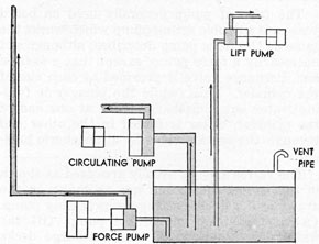
All pumps are generally classed under the three purposes for which they may be used. The sketch below shows that pumps are classed according to their purpose, and according to their position with the fluid supply.
CLASSES OF PUMPS
Pumps are used to transfer fluids from one place to another, but for clarity, it will be assumed that water is the liquid being pumped throughout this discussion.
If the pump is located at a distance above the liquid supply it is termed a lift pump. The distance that the pump is above the liquid supply is termed the "lift" of the pump. Some pumps have very little lift, and are used to discharge large quantities of water under little pressure. In this case, the pump is classed as a circulating pump.
Where a pump is to be used for discharging smaller volumes against high head pressures, it is classed as a force pump.
First, consideration is given to the lift pump. Pumps of this class, being located some distance above the liquid supply, demand more consideration on the suction side than on the discharge side.
In order to understand the operation of this class of pump, the theory of vacuum and
atmospheric pressure must be understood. First of all, there is no such thing as a drawing force, or sucking force as is ordinarily imagined. Flow of fluids is never caused by one pulling from the other, but always caused by one under a higher pressure pushing against the one with the lower pressure.
Atmospheric pressure is 14.7 pounds per square inch and the pressure of perfect vacuum is 0 pounds per square inch. It is impossible to obtain a perfect vacuum. Therefore, it is impossible to reduce pressure down to 0 pounds per square inch, and whenever the pressure is reduced below atmospheric pressure, but above a perfect vacuum, this is known as a partial vacuum. The pressure being above 0 pounds per square inch, then this partial vacuum has a small pressure, but a pressure nevertheless.
Now, the mercurial barometer operates under the fact the atmospheric pressure at sea level is capable of holding up a column of mercury approximately 30", and when the pressure rises, or falls, the column of mercury rises and falls. If water were substituted for the mercury, the water, being much lighter than mercury, could be held up by atmospheric pressure to a distance of 34'. This is only true if the water used is absolutely pure, and assuming that a perfect vacuum is maintained at the top of the column, and that there is no friction involved between the water and pipe.
The lift pump, when it begins operating, does not draw the water into the pump chamber, because, as has just been explained, this is not possible. The pump plunger, however, pumps the air out of its chamber, and displaces the air in the suction line, thereby reducing the pressure in the suction line below that of the atmosphere, causing the atmospheric pressure, acting on the surface of the water through the vent pipe, to push the water up through the suction pipe into the pump chamber, where it may be acted on by the pump plunger, and discharged.
Any pump, in order to lift water must be able to pump air. All pumps can not pump air, and those that can are capable of displacing anything in the pump chamber, and are known as positive displacement pumps.
90
RECIPROCATING PUMPS
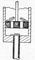
Simplex Type-All reciprocating pumps consist of a cylinder in which a close fitting plunger is moved back and forth. A simple type known as a lift pump is shown. This consists of a cylinder and plunger with a suction valve
LIFT PUMP
at the bottom of the cylinder and a valve in the plunger. The illustration shows the plunger on the down stroke, the suction valve is shown closed, the plunger valves are open, permitting air in the cylinder to flow above the plunger as it moves down. On the upward stroke, the plunger valves close, and the suction valve opens, permitting air in the suction line to flow
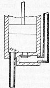
FORCE PUMP
into the cylinder. After a few strokes the air pressure in the cylinder and suction line are reduced sufficiently to allow the atmospheric pressure to force the water from the supply up the suction line into the cylinder. From here on the pump continues the same action, but moves water instead of air. This type of pump is used for lifting water only. Practically, water can be raised about 25 feet with a lift pump.
A simple sketch of a force pump is shown in
the accompanying drawing. Water is forced up into the pump cylinder by atmospheric pressure as the pump reduces the pressure in the cylinder and suction line. Instead of admitting air or water to the top of the plunger through a valve, on the down stroke it forces the water or air through the discharge valve. The height to which the water may be forced depends upon the power applied to the plunger. Both pumps described are single acting pumps as they move water out of the cylinder only on every other stroke of the plunger.
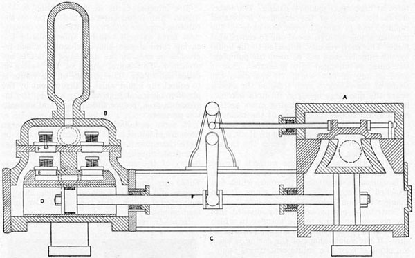
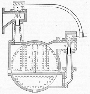
The type of pump generally used on board vessels is a double acting pump which works the same as the force pump described, although not necessarily a force pump, except that a suction and discharge valve is provided at each end of the cylinder. Thus, while the plunger is forcing water out a discharge valve at one end of the cylinder, water is forced in the other end through the suction valve by atmospheric pressure.
The valves are not usually arranged as shown in the simple sketch but are as shown in the drawing of a double acting reciprocating pump. (A) is the steam end of the pump, (B) the water end. Suction (E) and discharge decks (F) are provided above the cylinder and the suction and discharge valves are placed on these decks. The discharge deck is placed above the suction deck, a suction chamber is between the suction deck and the cylinder. The ends of the cylinder are connected by ports to the space above the suction valves and are separated by a division plate. (C) is the pump frame between the steam and water ends.
Duplex Type-The pumps which we have spoken of so far are known as simplex pumps, due to one pump cylinder being used. The discharge from this type is irregular due to the plunger reversing its direction after each stroke. For this reason a pump having two cylinders was developed, one plunger starting stroke before the other plunger has finished its stroke. This action gives a much smoother discharge than is possible with the simplex pump.
The duplex pump requires twice the number of valves used in a simplex pump, that is, at least four suction valves and four discharge valves.
In the steam reciprocating pump, the plunger is driven directly by a steam piston through a piston rod. Steam is admitted to first one end of the steam cylinder and then to the other, moving the steam piston back and forth. The
admission of steam is controlled by a slide valve, opening ports to the cylinder for steam to flow through.
The valve is controlled in a different way in the simplex pump than in the duplex pump. In the duplex pump the slide valve for one cylinder is controlled by the piston rod of the other cylinder. Thus as one piston nears the end of its stroke it causes the slide valve of the other cylinder to slide on its seat, opening ports, admitting steam, thus starting the other piston on its stroke.
For best results, in the simplex pump an auxiliary valve is controlled by the piston rod, which admits steam to one side of an auxiliary piston in the steam chest, which in moving in a cylinder, slides the main slide valve in the proper direction to admit steam to the cylinder, starting the piston on a new stroke.
Starting Reciprocating Pumps-In starting a reciprocating pump the following operations should be followed.
1. Make sure pump is clear and free to operate.
2. Open proper discharge valve.
3. Open proper suction valve.
4. Open cylinder and steam chest drains.
5. Open exhaust valve.
6. Crack steam valve, starting pump.
7. Close drains.
8. Regulate speed.
9. Lubricate.
CENTRIFUGAL PUMPS
If a pail partly filled with water is whirled in a circle, the water will stay in the bottom of the pail, in fact, the water will tend to force itself through the bottom of the pail. This action is due to what is known as centrifugal force. Centrifugal force is a force set up by whirling a body in a circle, which tends to cause that body to fly off at a tangent to the circle.
Mud guards are used around wheels because of the mud and water being thrown off the wheels due to centrifugal force.
A centrifugal pump is a pump that causes the flow of a liquid due to this force. It consists essentially of a motor or impeller which is
92
rotated at high speed inside a casing. The water enters the center of the impeller, is rotated rapidly, and is thrown from the ends of the impeller blades at high speed due to centrifugal force. This high velocity, imparted to the liquid by the impeller, can not be used for pumping, but must be changed into pressure. This is done in one of two ways. In one case, the shape of the casing is such that, as the casing nears the discharge opening, its area becomes larger and larger, or the casing cross section has a spiral shape. This shape of the casing is called volute. This volute-shaped casing causes the liquid to slow down and build up static pressure. Thus when the liquid leaves the casing, it leaves under a pressure.
In the other case, when the water is thrown from the blades of the impeller at high speed, it is caused to flow through vanes, which are attached to rings called diffusion rings. It also changes the high velocity into pressure.
Centrifugal pumps are usually divided into two classes according to the manner in which the velocity of the water is changed into pressure. If the volute shape of the casing is used, the pump is termed a volute centrifugal pump; whereas, if diffusion rings, containing diffusion vanes are used, the pump is termed a turbine centrifugal pump.
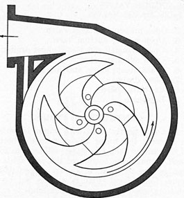
VOLUTE CENTRIFIGAL PUMP
If there is only one impeller contained in the casing, the pump is known as a single-stage pump. A single-stage centrifugal pump of the volute type class is shown in the accompanying drawing.
The impeller turns in the direction of the arrow. The liquid entering the center of the rotating impeller is thrown outwards by centrifugal force at high velocity. The walls of the casing form a spiral-shaped chamber which increases in area as the discharge outlet is approached. This spiral shape of the casing is called the volute. The purpose of the volute is to collect the liquid which is thrown out by the impeller blades at high velocity and, by the increase in area, reduce the velocity and increase the pressure.
In some installations, where the discharge pressure obtained is not sufficient, there may be more than one impeller contained in a casing. The first impeller discharges directly into the center of the second impeller, etc., each succeeding impeller building up more pressure. These are known as multi-stage centrifugal pumps and consist of more than one impeller connected in series. This type is used for boiler feed pumps.
In other installations, where a tremendous
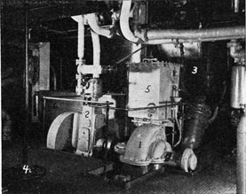
CENTRIFUGAL MAIN CIRCULATING PUMP
The above picture shows centrifugal type circulating pump (I), driven by a single cylinder reciprocating steam engine (2). The pump takes its suction from the sea through the main injection valve (4), and discharges into the cooling water side of the main condenser (3).
The steam control valve to the engine is equipped with an extension rod to the topside, as is the main injection valve. This permits stopping the main circulator and closing the main injection from outside the engine room in an emergency.
The engine cylinder drain valves are also visible. (5) is the observation tank for examining the returning condensate from the fuel oil heaters for presence of fuel oil. (6) is the feed and filter tank.
93
volume of liquid is required, such as some fire pumps, in order to reduce the size of the pump, more than one impeller is inclosed in a casing, all of them taking suction from the same suction line, and all of them discharging into a common discharge line. These are pumps in parallel, and with little effect on the pressure, are capable of discharging large quantities of liquid.
By themselves, centrifugal pumps of both classes have the disadvantage of being unable to displace air and reduce the pressure in the suction line below that of the atmosphere. They are therefore unable to lift water from a level below the pump suction. They are the only type of pump which are not positive displacement pumps.
ROTARY PUMPS
Where a service requires the lifting of small volumes of liquids, and the delivering of it with an even flow against an appreciable head pressure, rotary pumps of the positive displacement type have, to a large extent, replaced reciprocating pumps. Their pumping action is accomplished by rotating gears, screws, or tumblers inside a casing.
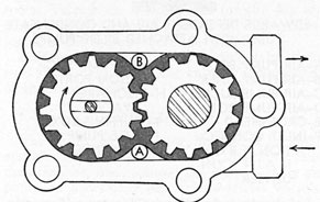
There are many types and designs of rotary pumps, the most common being the gear and screw pump. A gear pump is shown here.
GEAR PUMP
Gear Type-The gear pump usually consists of two gears, meshing together, caused to rotate within a close fitting casing. One of the gears is turned by an engine or motor, and in turn, rotates the second gear. The liquid enters at the bottom of the pump at (A), is carried between the gear teeth of each gear around the inside of the casing, and when the teeth mesh the liquid is displaced and forced out through a discharge opening, (B).
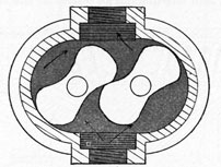
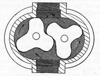
Another form of this pump uses two rotors with lobes on each rotor. The two rotors mesh together. The lobes act in the same way as the gear teeth, carrying the liquid around the inside of the casing, displacing the liquid when a lobe on one rotor meshes between two of the lobes of the other rotor. This type of rotary pump must have meshing gears on the same shafts, or timing chains to keep the lobes of both rotors spaced so that they mesh at the
TWO LOBE CYCLOIDAL PUMP
center of the pump. In the drawing of the lobe type pump, known as a cycloidal pump, the liquid enters at the bottom and is discharged at the top as indicated by the arrows.
These pumps may contain rotors of two or three lobes, and these lobes engage with a rolling motion.
THREE LOBE CYCLOIDAL PUMP
Screw Type-Screw pumps are rotary pumps using rotating screws to create the pumping effect. They consist of two shafts, each shaft carrying a left and right-hand screw. One shaft is driven by the power unit, and imparts its motion to the other shaft through a set of gears. These gears also act as timing gears.
The screws must be contained in a close fitting casing. The liquid enters the pump at the bottom, and floods the casing. The ends of the threads cut into the liquid, trapping quantities
94
of it into the spaces between the threads. The meshing of the threads prevents the escape of liquid from these spaces.
The threads, being right and left-handed, move the liquid from either end towards the center of the shafts, where it is discharged from the outlet to the line.
The accompanying sketch shows the rotating parts of the screw pump enclosed in the tight fitting casing. It shows the liquid inlet at the bottom, and the discharge outlet at the top. The
SCREW PUMP
arrows showing the flow of the liquid through the pump denote that the liquid enters at the ends of the threads and is discharged at the center.
This is an excellent type of pump for services such as the fuel oil service pump.
Rotary pumps of the gear and screw types should not be used for pumping liquids containing abrasives such as sand, grit, etc., because any wear of the pump parts will materially reduce the efficiency of the pumps.
AIR PUMPS AND VACUUM
A certain amount of air and non-condensable vapor unavoidably enters the condenser. As the condenser operates at a pressure below atmospheric pressure, this air is also at a pressure below the atmosphere; and in order to remove it, some apparatus must be furnished that will compress this air to above atmospheric pressure.
There are two mechanisms in general use for removing this air; one called an air pump and the other an air ejector.
Air pumps are divided into two general classes: wet and dry. A wet air pump handles both air and condensate. A dry air pump handles air only, with a separate pump handling condensate.
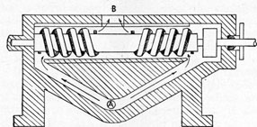
Dependent Air Pump-In marine practice, the wet air pump is more commonly used than the dry. The common method of driving the pump is to attach it to the L.P. crosshead of the main engine, of the reciprocating type. The Edwards
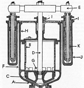
air pump is in general use and a sketch of this type is shown. In this particular pump all valves are dispensed with, except those for the discharge. The air and water, or condensate, which collects in the base of the pump is displaced and forced into the pump cylinder by the descending plunger. It is then caught above the plunger when it makes an up-stroke and is discharged through the discharge valves.
EDWARDS DEPENDENT AIR AND CONDENSATE
PUMP WITH ATTACHED BILGE PUMPS
A-AIR PUMP BODY
B-AIR PUMP LINER
C-AIR PUMP BUCKET
D-AIR PUMP ROD
E-CROSSHEAD
F-INLET CONNECTION FROM MAIN CONDENSER
G-AIR PUMP SUCTION PORTS
H-DISCHARGE VALVES
I-STUFFING BOXES
J-BILGE PUMP CYLINDER
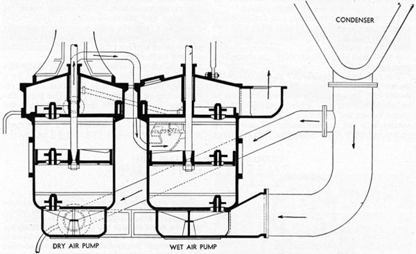
Independent Air Pump-This type, formerly used with turbine installations, has largely been replaced with air ejectors and condensate pumps as a means of removing air and condensate from main condensers. Independent air pumps consist of two pumps, one for removing the condensate and the other for air. In the cross-section view the wet air pump removes the condensate from the condenser and discharges it out of the top of the pump to the feed and filter tank as shown by the arrows. The dry air pump takes its suction higher up on the main condenser thereby taking only air. The air is discharged
95
INDEPENDENT AIR AND CONDENSATE PUMP
out of the top of the pump to the engine room. To provide a liquid seal for the dry air pump plunger, a small amount of water is injected at the bottom end of the pump.
Independent air pumps are driven by their own steam cylinders being entirely independent of the main engine.
AIR EJECTOR
The steam jet air ejector, because of its small space, weight, and economy of operation and maintenance, has replaced the reciprocating air pump on practically all turbine-driven vessels, and in some cases is used with reciprocating engine installations.
An ejector consists essentially of a steam nozzle discharging a jet of steam at high velocity across a suction chamber. The air and non-condensable vapors enter the suction chamber, are entrained by the jet of steam, and discharged into a compression tube where the velocity is reduced and the pressure increased before discharging.
This is known as a single-stage air ejector, but, since it is necessary to discharge the air into the atmosphere, the required discharge
TWO STAGE AIR EJECTOR
96
pressure cannot be economically obtained by the use of just one set of steam nozzles.
To attain higher vacuums, and for increased economy, air ejectors are usually built with two or more jets in series. They are known as multi-stage ejectors.
A two-stage air ejector is shown in the accompanying sketch.
The first-stage nozzles (A) at the top of the sketch take their suction from the main con-) denser and discharge into a chamber known as an intercondenser (B) where a portion of the steam vapors are condensed. The second-stage nozzles (C) pull the remaining air and steam vapors out of the intercondenser and discharge
them into the after condenser (D) where all vapors are condensed. The cooling water for the inter and aftercondensers is fresh water condensate from the main condenser condensate pump. The inter and aftercondensers may be of the jet or surface type. All of the condensate returns to the feed system.
When air ejectors are used, the condensate formed in the main condenser is removed by a separate pump which may be either of the reciprocating or centrifugal type. The pump discharges the condensate through the inter and aftercondenser to the open type deaerating feedwater heater. (See steam and water cycle on page 86.)
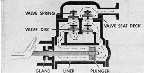
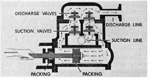
LIQUID END DOUBLE ACTING PUMP
The arrows indicate the flow of liquid as the plunger is moved forward. A partial vacuum is created behind the plunger. Atmospheric pressure is now sufficient to force the liquid through the suction valves, filling the spaces behind the plunger. At the same time liquid is pushed through the discharge valves by the plunger. This discharge pressure aids the springs in holding the suction valves closed and forces the discharge valve open.
By following the arrows the reader can see that on the return stroke the same cycle of events takes place. The hand shown on the piston rod is representative of the steam cylinder which transmits power through the piston rod to the liquid plunger. Each stroke of a double acting pump is a power stroke and the result is a steady, unbroken flow.
97
REMEMBER-BILGE WATER OIL SLICK CAN BE TRAILED
PUMPING SYSTEMS
For the ship's safety and operation the following pumping systems are needed. The pumps are usually located in the engine room.
Bilge System-Into the engine room bilges flows the cooling water discharging from the main bearings, guides and thrust bearing. Sea water also enters the bilge from the stern gland.
To remove this water and discharge it overboard, a pump known as the bilge pump is used. It is an independent pump usually of the steam reciprocating type. The pump takes its suction through a pipe line from wells in the forward and after ends of the engine room bilge. The fireroom bilge is likewise equipped. Around the open end of the suctions is placed a strainer in the form of a perforated steel plate, to prevent rags, etc., from entering the pipe. These are sometimes known as rose boxes. If the bilge pump refuses to remove the water, look at the rose boxes to see if they are not plugged.
Many reciprocating main engines have what are known as bilge rams on the side of the dependent air pump. These act as bilge pumps when the main engine is operating, the regular bilge pump being kept for port use.
Do not pump bilge water overboard except at authorized times. You may leave a trail of oil behind your ship that the enemy can follow.
Ballast System-When a ship is running without cargo it rides high in the water. Should heavy seas blow up, it will be necessary to bring the ship down further in the water in order to handle it. This is done by pumping sea water through pipe lines into the empty fuel oil storage tanks in the double bottoms. This is known as ballast. The pump for this purpose is known
as the ballast pump. On the suction and discharge sides of the pump are valve manifolds, which are simply several valves in one body. Each valve wheel has a name plate, upon which is stamped the particular tank that the pump is sucking from and discharging into. By opening and closing the different valves, ballast may be pumped from any one tank to any other.
Valve manifolds are also used with other pumps, such as the fuel oil transfer pump.
Sanitary System-To supply sea water for the various toilets aboard ship a steam pump known as the sanitary pump is provided. It takes its suction directly from the sea and is usually controlled by an automatic pressure regulator so that the pressure in the sanitary line remains constant no matter how much water is being used.
Do not flush toilets in daytime. You may give away the location of your ship to the enemy.
The cooling water for the refrigerating machine is quite often taken from this line.
Fresh Water System-For washing purposes, fresh water is pumped from the fresh water storage tanks through pipe lines to the lavatories in the crew's quarters and to the showers in the washrooms.
Water for drinking and cooking is pumped from the domestic tanks to the galley and drinking fountains. In some ships a gravity tank is provided on the boat deck, in which case the drinking water would be pumped from the domestic tanks to the gravity tank, from where it
98
would run by gravity to the galley and fountains.
Fire Main-For fire fighting purposes a special pump known as the fire pump is provided. It takes its suction from the sea and discharges it through the fire line the length of the ship. Convenient
fire hose connections are located along the fire line to permit a fire at any point in the ship being reached by the fire hose.
Fire pumps must be ready for instant service and the method of starting up should be thoroughly understood by the engine room crew.
99
ELECTRICITY
For many years American ships have been equipped with electric lights. Prior to that, oil lamps were used for running lights and illumination in crew's quarters, engine and firerooms. Electricity for these lights and to operate electric motors is produced in an electric generator which is driven by a steam engine, either reciprocating or turbine.
ELECTRO-MAGNET
The electricity produced flows to all parts of the ship requiring light and power, through copper cables in much the same manner as water flows through pipes. There is nothing complicated about the principle of electricity if it is compared with a liquid. If water is pumped through a pipe line under pressure, the amount of pressure in lbs. per sq. in. is determined by looking at the pressure gage. The pressure of electricity is known as volts and is determined by looking at the voltmeter on the switchboard.
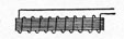
ARMATURE
The rate of flow of a liquid may be spoken of in gallons per minute. The rate of flow of electricity is known as amperes and is determined by looking at the ammeter on the switchboard.
To find the amount of work being done by an electric current, multiply the volts by the amperes. This results in watts. A thousand watts is a kilowatt, known as K.W. On the name plate of generators is stamped the maximum K.W. capacity of the generator. This should not be exceeded.
Electricity, if allowed to flow through the human body, can easily be fatal even though the voltage is low. The amount of amperes has the greatest effect on the body. When working around electricity take every safety precaution.
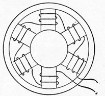
GENERATORS
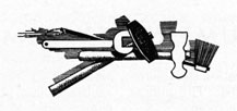
Electricity is generated by the cutting of magnetic lines of force by wires in a closed circuit. The magnetic lines of force are created by field poles, which are really electro-magnets. An electro-magnet consists of an iron core with a coil of wire around it, electricity passing through the wires of the coil.
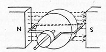
FIELD POLES
The wires which cut the magnetic lines of force are wound on the armature of the generator. The armature is connected to the engine or turbine and is rotated between the field poles, which are stationary. As the electricity is generated in the wires of the rotating element, it must be taken from it. To do this, carbon brushes bear against a commutator to which the armature windings are connected. The commutator consists of copper segments, each one
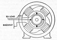
GENERATOR
insulated from the next one, and also insulated from the armature shaft. Each coil has one end connected to one segment and the other end to a segment on the opposite side of the commutator. The brushes which bear against the commutator are arranged so that one of them will connect one end of the coil to the outside circuit, thus making a complete circuit. The brushes connect
100
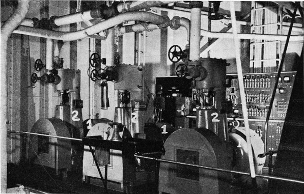
GENERATORS AS INSTALLED ON LIBERTY SHIP
The above picture shows three 110 volt, 20 K. W., D. C. generators (I), driven by single cylinder reciprocating steam engines (2). The switchboard is visible aft of the generators with cables leading up from it to the various parts of the ship.
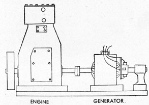
It is most important that the oiler be thoroughly familiar with the lubrication of the steam engine. The lubrication of the main bearings, crankpin bearings, crosshead bearings, guides, eccentric and valve gear bearings is automatic, being supplied by an oil pump located in the oil sump in the base of the engine frame. The pump is operated from the crosshead by a rod or chain drive from the crankshaft. The oil discharges upward through a pipe line to a gravity sight feed oil box seen on the side of the engine just below the cylinder. From here the oil flows by gravity through needle type regulating valves to each bearing. A glass window in the side of the box enables the oiler to see whether or not oil is flowing to each bearing. The level of the lubricating oil in the sump is determined by looking at the gage glass in the side of the engine base. Oil should be added from time to time to keep the proper level.
The generator shaft bearing may be either of the ring oiled type or a sealed ball bearing requiring little attention except to feel it each round.
The piston rod and valve stem are swabbed with cylinder oil each round. The packing should be kept from leaking as the escaping steam tends to travel down the valve stem and piston rod into the crankcase where it mixes with the lubricating oil, forming an emulsion. This emulsion is not a proper lubricant.
As generators must operate at a constant speed no matter what the load, a speed governor, usually of the wheel or shaft type, is provided on the engine. This type governor regulates the length of the valve travel thereby controlling the amount of steam entering the cylinder.
In the picture may also be seen the steam and exhaust valves, the larger valve wheel being the steam. Cylinder relief valves are also visible. The engine balance wheels are covered with a guard to prevent injury to crew members in event of being thrown against them.
The generator commutator must be kept dry and clean. Lubricating oil should never be used on it. To clean the commutator the generator is revolved slowly with the brushes removed, holding a clean dry rag or very fine grade of sandpaper on it.
When checking a generator, as when checking any other auxiliary machinery, any unusual noise or sound should be noted and reported at once to the engineer.
101
to a main switch on the switchboard, from which electrical circuits lead to the lights and motors on the ship.
A complete circuit is necessary for electrical current to flow. Therefore when no electricity is being used, there is no flow of electrical current. When lights are on or motors started, the circuit is completed and electricity flows through the circuit.
As a flow of electricity is necessary for an electromagnet to work, and as field poles are electro-magnets, electricity from the armature is led to the field coils. This creates magnetic lines of force between two poles.
When starting up a generator, the necessary magnetism is provided by that held by the iron cores of the field poles. This magnetism is known as residual magnetism.
ENGINE GENERATOR
From the main switch, the lines carry the electricity to a circuit breaker. The circuit breaker is a device which automatically opens the whole circuit in case of an overload. Thus the circuit breaker is a protective device for preventing the overloading of the generator. An overloaded generator will heat up, causing burned insulation and short circuits.
Lines from the circuit breaker connect to switches that control the individual lighting and power circuits of the ship. These lines are heavy copper bars and are known as busses or bus bars. The individual circuit switches are equipped with fuses, which melt if too much load is applied to that circuit. Thus the fuses are a protective device for preventing too high a load on any one circuit.
If the circuit breaker opens, some of the load (lights and motors) must be reduced, and the circuit breaker may then be closed by moving the handle back to closed position. If a fuse melts, or blows out, as it is called, a new fuse is placed in position after some lights or motors
are shut off. In some types of fuses the fuse may be taken apart and a new fuse link put in place of the melted one.
The switchboard also has a voltmeter and an ammeter installed on it. The voltmeter is to show the voltage of electricity generated. In marine practice this is kept at around 120 volts. The voltage is controlled by the number of magnetic lines of force cut by the armature windings. This in turn depends upon the speed of the armature, and the current flowing through the field coils. As the speed of the armature is kept constant by the governor of the engine or turbine, the voltage must be controlled by the amount of current flowing in the field coils.
In practice the voltage is controlled by a rheostat located on the switchboard. The control wheel is turned one way to increase the voltage and the other way to decrease the voltage. The rheostat controls the amount of current flowing through the field coils, thus controlling the voltage.
The ammeter shows the amount of current that is being used by the lights and motors of the ship. The current is measured in amperes, the amount depending upon the size and number of lights and motors in use.
PROPER METHOD OF CHANGING OVER GENERATORS
Generators are ordinarily started and stopped by the engineer but it is well for the oiler and watertender to understand the procedure. They may be called upon to assist at any time.
When a ship has two generators, one is in service while the other stands by. At regular intervals, probably once a week, the stand-by is started up and the in-service one shut down for a week. This is known as changing over the generators.
To start a generator the following procedure should be followed:
1. Make sure circuit breaker and main switch on the switchboard are in the open position.
2. Make sure generator is clear by revolving it one revolution by hand.
3. Check commutator to make sure brushes are in place.
4. Check lubricating oil level in engine.
5. Open cylinder and steam chest drains.
6. Open exhaust valve.
7. Crack steam valve, allowing engine to run slowly until warmed up.
102
8. Check lubrication.
9. When engine is warmed sufficiently, bring up to full speed.
10. Close drains.
11. Adjust rheostat to bring voltage up to a few volts above the bus voltage.
12. Throw in circuit breaker.
13. Throw in main switch.
The following procedure should be followed when shutting down a generator:
1. Take most of the load off the machine.
2. Trip the circuit breaker.
3. Pull out the main switch.
4. Close steam valve to engine.
5. When machine stops close exhaust.
6. Open drains.
103
DECK MACHINERY
To lift cargo aboard and ashore, pull in the mooring lines and raise the ship's anchors, machinery is required. As it is usually located on the open deck, it is known as deck machinery. These include cargo winches, capstans and anchor windlass, which may be driven by steam engines or electric motors.
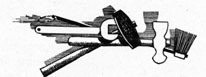
STEAM CARGO WINCH
A-DRUM
B-NIGGER HEAD
C-DIFFERENTIAL VALVE
D-STEAM CHEST
E-CYLINDER
F-DIFFERENTIAL VALVE CONTROL LEVER
G-CROSSHEAD
CARGO WINCH
Steam winches consist of two steam engines connected to the same crankshaft. The two cranks are at 90 degrees so that the winch will always start no matter what position it is. The crankshaft is connected to a drum by means of reduction gearing. Wire is wound on the drum, which turns at a much slower speed than the crankshaft. The other end of the wire is carried up a cargo boom and is used to transfer cargo from the hold to the dock or vice-versa. A brake is usually fitted to the drum of the winch, controlled by a foot lever so that the winch may be held with a load on it when the steam is shut off. Steam to cargo winches is controlled by an operating lever which moves a differential valve, working in the same manner as described on reversing engines. The winch is thus reversible, the differential valve controlling the speed and direction of rotation of the drum.
A warping winch is supplied on the after deck for handling mooring lines. The winch is built on the same plan as the cargo winches but two nigger heads or gypsies are secured on the same shaft as the drum and geared down from the speed of the crankshaft. The cargo winches usually have one gypsy on the outboard side. The nigger heads are used to wind the mooring lines around so that as the heads are rotated the lines are drawn in.
The warping winch is usually made reversible, operated by a lever and differential valve. In some types a double reduction of speed is accomplished by another set of gears which may be brought into use by moving a lever. This reduces the speed of the nigger heads.
Electric winches are driven by an electric motor. The speed of the motor is reduced by gearing and the drum turns at a slower speed. The speed of the motor is controlled by a resistance box and handle.
E-NIGGER HEAD
F-CYLINDER
G-STEAM CHEST
H-DIFFERENTIAL VALVE
ANCHOR WINDLASS
On the forecastle head an anchor windlass is situated for the purpose of hoisting anchors and handling mooring lines. The anchor windlass consists of two reciprocating engines connected
104
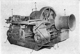
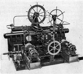
SCREW TYPE STEERING ENGINE
to the same crankshaft, as in cargo winches. The rotation of the crankshaft is communicated by gears to two wildcats into which the anchor chain fits. The dogs on the wildcats keep the chain from slipping. Each wildcat is held on its shaft by a clutch which may be slacked off entirely or tightened up so that either or both chains and anchors may be hoisted.
The wildcats are run much slower than the crankshaft due to the number of speed reducing gears used between the crankshaft and the wildcat shaft. Each wildcat is supplied with a brake, actuated by a hand wheel, so that when it is not secured to the shaft, the brake may be used to prevent its turning.
Nigger heads are secured to the ends of a higher speed shaft, thus turning faster than the wildcats. The nigger heads run whenever the windlass is turned over. They are used for handling mooring lines.
The windlass is the most powerful of the deck machines because not only may it be required to lift both anchors at the same time, but when the vessel is riding at anchor there are times when the full strain of the anchors and chains pull directly on the windlass. Being in the extreme bow of the vessel, it sometimes takes the brunt of the seas coming over in rough weather.
LUBRICATION
The various bearings of the winch and windlass steam engines are oiled by hand, the oil being squirted into brass oil cups filled with horse hair. The piston rods and valve stems have to be swabbed the same as any steam engine.
The winch and windlass bearings are generally lubricated by grease from grease cups on each bearing.
105
STEERING ENGINES
All vessels need a form of control with which to steer the ship. This consists of a rudder at the stern of the vessel, the rudder being moved by some mechanical device.
At present the two devices generally used are the steam engine, and the hydraulic ram. The steam engine usually consists of two cylinders with cranks 90 degrees apart, so that the engine will start from any position when steam is
admitted to the cylinders. The steam to the valve chests is controlled by a differential valve, as explained under reversing engines, to allow the steering engine to run in either direction. The crankshaft of the engine is attached by gears, quadrants or screws to the rudder post so that when the engine turns, the rudder is moved to turn the heading of the ship to port or starboard.
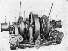
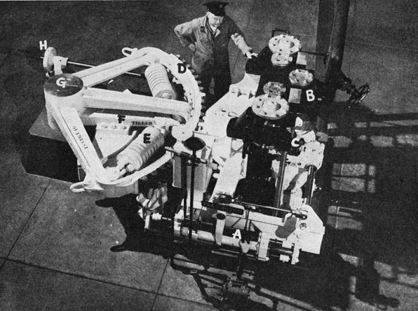
QUADRANT TYPE STEERING ENGINE
A-TELEMOTOR
B-DIFFERENTIAL VALVE
C-FOLLOW-UP GEAR
D-QUADRANT
E-SPRING
F-TILLER ARM
G-RUDDER POST
H-HAND BRAKE
In this illustration pinion and quadrant gears are painted to afford photographic contrast.
106
The differential valve is controlled from the bridge of the ship by the steering wheel. This is usually done in one of two ways; by gears and shafting reaching from the bridge to the steering engine or by telemotor.
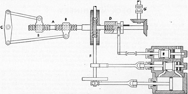
A sketch of a screw-type steering engine is given on page 104.
SCREW-TYPE STEERING ENGINE
The steam is admitted to the cylinder through the differential valve (E) which is controlled by steering wheel shaft (G). As the crankshaft (F) revolves, the worm also revolves, turning the large worm gear on the right- and left-hand screw shaft (A). The traveling nuts (B) move together or apart, depending on which way the engine is turning, and through connecting rods turn the rudder post (C).
In order for the steering engine to stop and hold the rudder when the steering wheel is stopped, the follow-up gear (D) is provided. This pushes the differential valve to the closed position, stopping the engine as soon as the man at the steering wheel stops turning it.
QUADRANT TYPE STEERING ENGINE
A very popular type on medium sized cargo vessels, consisting of a vertical two-cylinder steam engine with cranks set at 90° apart to permit starting of the engine at any point. A worm on the crankshaft meshes with a worm wheel upon a vertical shaft, upon which is a gear that meshes with the quadrant. The quadrant is connected through coil springs to the tiller arm. The springs take up some of the shock of the seas pounding against the rudder. As the engine operates in one direction or the other, the quadrant swings in an arc turning the rudder post and rudder.
The engine bearings are hand-oiled, having wick-feed gravity boxes.
The engine has a differential valve and follow-up gear the same as the screw type.
To lock the rudder in the event of one or more of the gears carrying away, a hand brake with control wheel is provided.
Steam steering engines usually exhaust direct to the main condenser instead of into the auxiliary exhaust line. In this manner there is no fluctuating back pressure for the engine to work against.
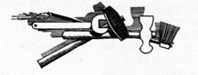
ELECTRO-HYDRAULIC TYPE STEERING ENGINE
In fast, modern ships this type is
predominant. A typical installation is shown in the illustration. It consists of an electric motor driven reversible pump which forces light oil into either end of a hydraulic ram. As the ram moves, it swings the tiller arm and rudder. By reversing the direction of the pump, the movement of the ram is reversed and so the rudder.
ELECTRO-HYDRAULIC STEERING GEAR
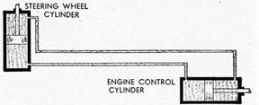
TELEMOTOR
The sketch shows the principle of the hydraulic telemotor. It consists of two cylinders connected by pipes. Each cylinder contains a close-fitting piston. The cylinders and piping are filled with a mixture of glycerine and water, or with a light oil. When one piston is moved it moves the other piston through the medium of the oil or glycerine mixture.
TELEMOTOR
One piston is attached to the steering wheel on the bridge, the other being attached to the differential valve by links, and lever arrangement. Thus, as the wheel on the bridge is turned, the piston in the steering engine room moves the differential valve, admitting steam to the engine.