Reciprocating type main engines have been used to propel ships, since Robert Fulton first installed one in the Clermont in 1810. The Clermont's engine was a small single cylinder affair which turned paddle wheels on the side of the ship. The boiler was only able to supply steam to the engine at a few pounds pressure. Since that time the reciprocating engine has been gradually developed into a much larger and more powerful engine of several cylinders, some having been built as large as 12,000 horsepower. Turbine type main engines being much smaller and more powerful were rapidly replacing reciprocating engines, when the present emergency made it necessary to return to the installation of reciprocating engines in a large portion of the new ships due to the great demand for turbines. It is one of the most durable and reliable type engines, providing it has proper care and lubrication.
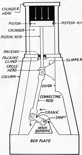
Its principle of operation consists essentially of a cylinder in which a close fitting piston is pushed back and forth or up and down according to the position of the cylinder. If steam is admitted to the top of the cylinder, it will expand and push the piston ahead of it to the bottom. Then if steam is admitted to the bottom of the cylinder it will push the piston back up. This continual back and forth movement of the piston is called reciprocating motion, hence the name, reciprocating engine. To turn the propeller the motion must be changed to a rotary one. This is accomplished by adding a piston rod, crosshead, connecting rod, crank and crankshaft. When the piston goes up and down it pushes the piston rod up and down with it. This through the crosshead pushes the connecting rod, the bottom end of which is attached to the crank. The crank is merely an arm, one end of which is fastened to a round shaft (crankshaft) free to revolve in a fixed bearing and the other end to the connecting rod. As the connecting rod is pushed up and down it pushes the crank around in a circle the hub of which is the crankshaft. A propeller attached to the end of the crankshaft will revolve at the same speed as the crankshaft.
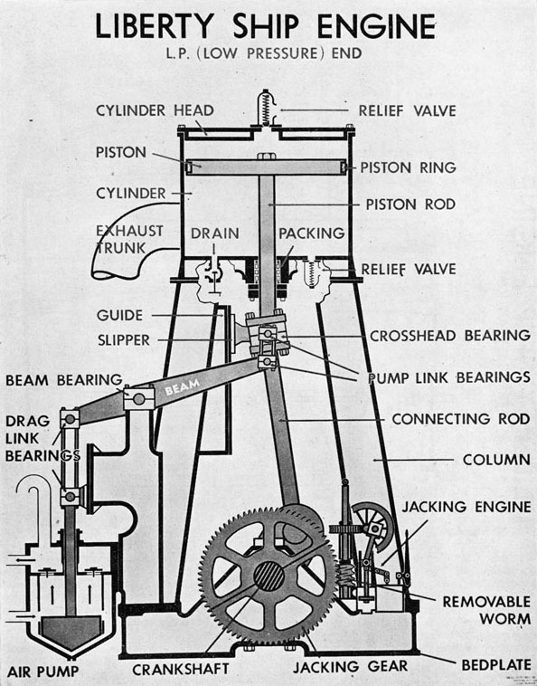
The hole in the center of the lower cylinder head through which the piston rod passes must be sealed otherwise steam will blow out. Packing is installed around the piston rod in the stuffing box for this purpose. For the packing
to be effective the piston rod must travel in a straight line and not move from side to side. This is accomplished by the guide and slipper shown in the drawing.
SIMPLE ENGINE
(Valve and valve gear not shown)
The slipper or shoe, as it is known, is attached to the crosshead and as it travels up and down the slipper is pushed by the angularity of the connecting rod against the guide which is a flat lubricated metal surface in line with the cylinder. Thus it is impossible for the piston rod to move sideways in its travel.
60
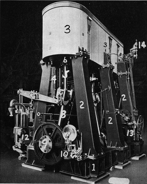
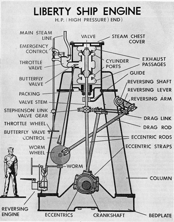
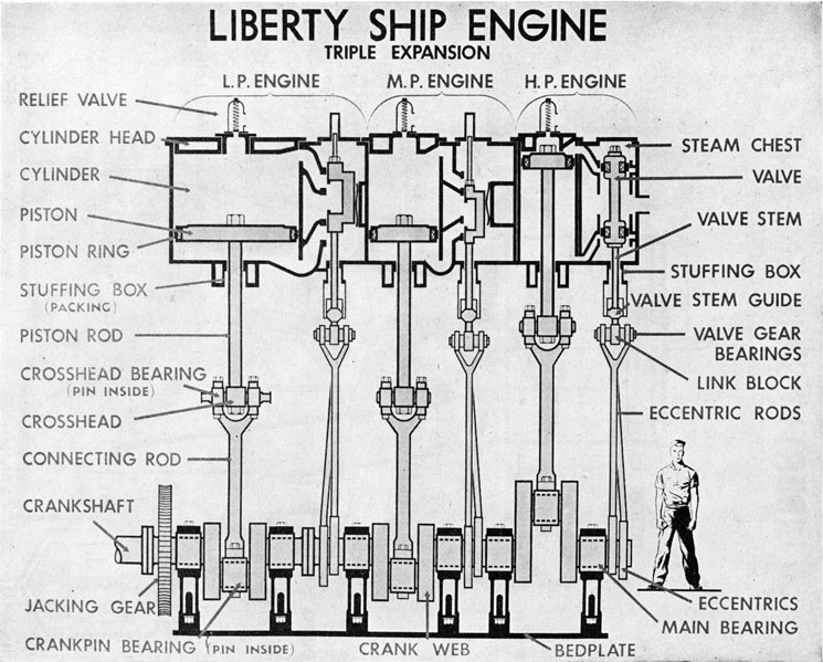
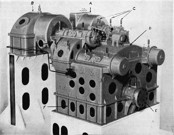
TRIPLE EXPANSION RECIPROCATING STEAM ENGINE FOR EC-2 (LIBERTY) SHIP
1. BEDPLATE
2. COLUMNS
3. CYLINDERS
4. GUIDE
5. PISTON ROD
6. PISTON ROD PACKING
7. CROSSHEAD
8. CONNECTING ROD
9. CRANKSHAFT COUPLING
10. JACKING ENGINE AND GEAR
11. AIR PUMP BEAM
12. DEPENDENT AIR PUMP
13. REVERSING ENGINE
14. THROTTLE.
61
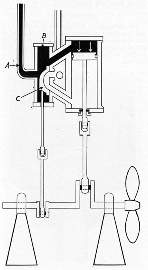
The alternate entry of steam to the top and bottom of the cylinder is made possible by an automatic valve (C) shown in the side view of a simple engine.
As shown in the sketch steam from the boiler enters the steam chest through the steam line (A) completely filling the chest (B). The slide valve, which is somewhat in the form of the letter D is in the down position, uncovering
SIMPLE ENGINE-CRANK ON TOP CENTER
In the above sketch the crank is shown in the top center position. The arrows indicate the direction of force and the movement of the piston. The valve will move up to cut off flow of steam to top of piston.
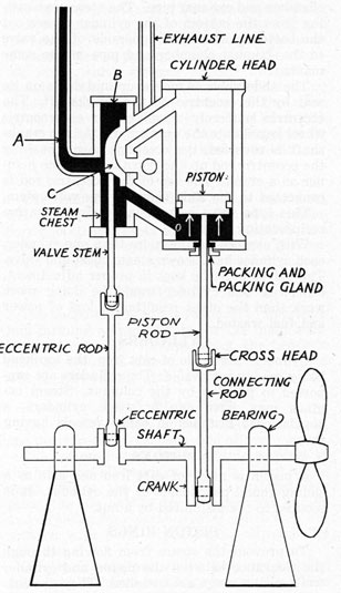
the top steam port (hole between the steam chest and cylinder) which allows the steam to flow into the top of the cylinder. When the piston has been pushed downward a short way the valve moves up, covering the top port, stopping the steam from entering. The steam in the cylinder expands pushing the piston ahead of it to the bottom of the cylinder. As the steam expands its temperature and pressure drop due
SIMPLE ENGINE-CRANK ON BOTTOM CENTER
The above sketch shows the crank on bottom center and the arrows below the piston indicate the upward force of the steam. In this case the valve will move down to cut off the flow of steam.
62
to its energy being converted into mechanical work. When the piston reaches the bottom of the cylinder the valve in the steam chest moves up still further, uncovering the bottom port which permits steam to flow into the bottom of the cylinder where it expands and pushes the piston back up in the same manner.
The steam which pushed the piston down is exhausted from the cylinder through the top cylinder port to the hollow underside of the valve where it is directed into the exhaust chamber and exhaust pipe. The steam exhausting from the bottom of the cylinder passes out the bottom port to the underside of the valve to the exhaust chamber and pipe in the same manner.
The slide valve is moved up and down on its seat by the eccentric on the crankshaft. The eccentric is merely an off center or eccentric wheel keyed onto the crankshaft. As the crankshaft is revolved, the eccentric turns, pushing the eccentric rod up and down in the same manner as a crank. The top of the eccentric rod is connected to the slide valve by the valve stem.
This type valve is used in nearly all marine reciprocating engines.
With engines having more than one cylinder, each cylinder has its own steam chest and valve. The valves must be kept in proper adjustment, otherwise one cylinder would be doing more work than the other resulting in loss of power and fuel wasted.
CYLINDERS
Cylinders are made of cast iron, the top head being readily removable. The cylinders are supported in position by the columns. Steam engines may have one or more cylinders, a popular size installed in cargo vessels having three.
PISTONS
A piston is made of cast iron and acts as a sliding round plug inside of the cylinder. It is secured to the piston rod by a nut.
PISTON RINGS
To prevent the steam from flowing through the clearance between the piston and cylinder walls piston rings are installed. They are constructed of fine grade cast iron and have a sliding fit in a groove around the outside of the piston. The plain snap type piston ring is made oversize and is held out tight against the cylinder wall by the tension in the ring, set up by its having to be compressed when installed. Improved piston rings of several different designs
are used in practically all main engines today especially in high pressure cylinders. These employ a separate spring to provide the tension for holding the piston ring out against the cylinder wall. By adjusting the tension of the spring the tightness of the ring is determined. If the rings are not kept properly adjusted steam will blow by the piston, resulting in loss of power and steam wasted. This can usually be detected by the readings of the cylinder pressure gages.
Lubrication must be provided between the piston rings and cylinder wall.
PISTON ROD
The piston rod is round, made of steel, the top end is secured to the piston, the bottom end to the crosshead. To prevent steam from blowing out of the cylinder around the rod, metallic type packing is installed around the rod in the stuffing box.
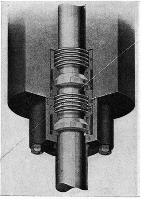
METALLIC PACKING
METALLIC PACKING
The cut-away view of a set of one type of metallic packing in place on a piston rod shows that the two metal rings (6) are the only parts
63
in contact with the rod. The metal used in this type packing is relatively soft, being a form of babbitt. The coil springs (10) provide the tension to hold the rings tight around the rod. The piston rod sliding through the metal rings must be lubricated otherwise the friction will cause overheating.
CROSSHEAD
A crosshead is a square steel block rigidly fastened to the bottom end of the piston rod. On the forward and after side of the block is a round steel pin known as the crosshead pin, around which the crosshead bearings fit. These bearings are rigidly fastened to the top of the connecting rod fork and in operation the bearings revolve back and forth around the pins and must be lubricated.
To the back side of the crosshead a slipper is attached.
SLIPPER
A slipper is made of cast iron with the flat bearing face being coated with babbitt metal. Some engines have one slipper and some two depending on whether it is a single or double guide engine. The great proportion of engines being built today being of single guide construction, the text will deal with that type.
GUIDES
The ahead guide is a flat face made of cast iron and bolted against the column. The astern guide consists of two cast iron side bars which fit around the outside of the slipper preventing it from being pulled away from the guide when the engine is turning in the astern motion. Lubrication must be provided between the sliding metal faces of the slipper and guides.
Guides are usually cooled by sea water passing through a core in the back of the ahead guide face.
CONNECTING ROD
The connecting rod is made of steel, the top end usually being forked in large engines and attached to the crosshead with bearings so that the crankpin is free to turn as the crank goes around. The crankpin bearing must be lubricated also.
CRANK
The crank is constructed of steel and consists of the following parts. Webs which are the two side pieces connecting the crankshaft with the crankpin. Crankpin which is a round steel pin between the outer ends of the crank webs, around which the crankpin bearing is fitted.
CRANKSHAFT
The crankshaft is a large round steel shaft to which the cranks are attached. Those portions of the shaft which revolve in the main bearings are known as journals. Mounted on the shaft are the eccentrics.
ECCENTRICS
The eccentrics which move the engine valves up and down are merely an off center or eccentric wheel secured around and keyed to the outside of the crankshaft. Two are required for each valve, one being for ahead motion and one for astern. The motion of the moving eccentric is transmitted to the eccentric rod by the eccentric strap which extends entirely around the outside of the eccentric, the eccentric turning inside of it. The inside surface of the strap which bears on the eccentric is either lined with babbitt metal or bronze. Lubrication must be provided between the strap and eccentric.
COLUMNS
The columns are made of hollow cast iron, box construction and are used to hold the cylinders and steam chests in position, two columns supporting each cylinder and chest. The columns stand on and are bolted to the bedplate.
BEDPLATE
The bedplate is securely fastened to the ship's hull forming a true surface for the main bearings and columns. In assembling, the bedplate must be true and ridged, otherwise the engine will be thrown out of line.
MAIN BEARINGS
The main bearings support the crankshaft, one being required on each side of every crank.
The bottom halves are fitted into a recess in the bedplate, all bearings being in direct alignment. When the crankshaft is lowered into place, the top half of the bearings are put on and adjusted for clearance after which they are secured with bolts which extend through the bedplate.
The inside surface of the bearings is lined with babbitt metal requiring lubrication. This is supplied through oil holes leading from the top of the bearings through to the shaft. Oil grooves cut in the face of the babbitt metal enable the oil to spread evenly the length of the bearings. The revolving shaft carries the oil entirely around the bearing
64
providing an unbroken film which keeps the metal of the bearing from coming in contact with the journal. This principle of lubrication applies to all bearings.
The lower half of main bearings on larger engines is usually cooled by sea water flowing through a core in the bearing shell.
CRANKPIN BEARING
The crankpin bearing is bolted to the bottom end of connecting rod and of same general construction as main bearings. Lubricated from oil cups on the crosshead, the oil passing down oil lines on the forward and after side of the connecting rod.
CROSSHEAD BEARINGS
The crosshead bearings are bolted to the top end of the connecting rod and may be constructed of brass or with a babbitt lining. Lubricated through an oil cup on top of the bearing.
PISTON VALVE
VALVES AND VALVE GEAR
The D-type slide valve is held on its seat by the steam pressure pushing against the back of it. This sets up considerable friction which requires a great deal of power to move the valve when high steam pressures are used. For this reason, another type of valve is used to a great extent on marine engines. This is known as a piston valve, and is, in fact, a flat slide valve developed into the form of a cylinder, presenting no flat surfaces upon which the steam may act.
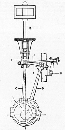
STEPHENSON LINK VALVE GEAR
The piston valve consists of two pistons joined by a hollow casting as shown in the drawing. The valve slides inside two removable sleeves or liners which form a cylindrical valve seat. Steam ports communicating with the ends of the cylinder are cored into the sleeves. The valve is secured to the valve stem and is controlled by the eccentric the same as a flat slide valve.
65
The steam may enter at the center of the valve, or at the ends of the valve. The exhaust piping connects just the opposite from the steam inlet. In the drawing, the steam enters at the center, and this is known as an inside valve. It is impossible to use a slide valve as an inside valve, as the steam pressure acting under the valve would force the valve from its seat. Therefore, a slide valve is always an outside valve.
If steam pressure is allowed to enter the cylinder during the full stroke of the piston, it would be a very expensive engine to run. For this reason, the steam is permitted to enter the cylinder only during part of the stroke. During the rest of the stroke, the steam expands in pushing the piston through the cylinder. Thus the expansive quality of the steam is used for doing work.
As the marine engines must be reversible in order for the ship to be made to go ahead or astern, we must have some way to cause the reciprocating engine to run in the opposite direction. In almost all types of reciprocating engines used on board ship for propulsion, we use the type of valve mechanism shown in the drawing. This consists of two eccentrics (A) and what is known as a Stephenson link. One eccentric is set to control the valve for go-ahead motion and the other eccentric is set to control the valve for go-astern motion.
An eccentric rod (C) is run from one eccentric to one end of the link (E) and another eccentric (D) to the other end of the link. This is clearly seen in the drawing. The link is made to slide along a block (F) attached to the foot of the valve stem (G). The valve is thus moved by the eccentric whose eccentric rod is directly beneath the valve stem. This type of link is known as the Stephenson link.
The link is made to move by a reversing ram or reversing engine. The engine or ram turns a rock shaft (H), mounted on a back column, by means of a connecting rod. The rock shaft connects to the Stephenson link by means of drag links or tie rods (I) as shown in the drawing. The rock shaft in turning through a part of a revolution throws the links from ahead to astern, or from astern, to go ahead, as the case may be.
If the link is moved until the center of the link is directly under the valve stem, with the throttle open, the engine would not run. This is due to the fact that the eccentrics operate against each other and the center of the link
has no up and down movement. By using this knowledge, if the link is moved from one eccentric, a short distance toward the other, the amount of steam that will be admitted to the cylinder will be less than if the valve stem were directly over the eccentric rod. By moving the link in this fashion, the valve travel will be less. With less valve travel, total distance the valve moves, the valves will close the steam port to the cylinder earlier in the stroke, cut-off is sooner. With earlier cut-off less steam is admitted to the cylinder which takes us back to the statement, that if we move the link from one eccentric a short distance toward the other, the amount of steam that will be admitted to the cylinder will be less and the amount of work accomplished is less. The amount of steam admitted will be less due to a shorter valve travel giving an earlier cut-off.
On marine propulsion engines, it is possible to move the links on each individual engine by the use of an individual cut-off gear which has the reversing rocker, or the rock shaft, slotted at the end. The tie rods, reaching from the Stephenson link to the reversing rocker are attached to a movable block, that is closely fitted into the slot. By means of a screw, the block may be readily moved to the right or left, thus moving the link either toward mid-gear or full gear ahead, without affecting the other links. That is, the cut-off on the H. P. and M. P. and the L. P. may each be independently adjusted with the engine stopped or with the engine in motion.
When the rock shaft is turned to its astern position, the slot in the reverse rocker arm will be vertical, and thus the cut-off gear has no influence on the astern power of the engine.
REVERSING ENGINES
On the Liberty ships a reversing engine is used to move the Stephenson links from ahead to astern or astern to ahead. This is known as "throwing the links." The reversing engine is a small single cylinder steam engine with the cylinder on the bottom and crankshaft on top as shown in the chart on page 68. The reversing engine is controlled by a lever on the H. P. front column.
As the reversing engine runs, the rotary motion of the crankshaft turns the worm which is keyed on the reversing engine crankshaft. The worm meshes with the worm wheel and causes it to turn. The pin is connected to the reversing shaft of the reverse gear by a drag
66
rod. Half a revolution of the worm wheel causes the connecting rod to the rock shaft to turn the rock shaft sufficiently to throw the links from ahead to astern or astern to ahead and thus change the direction of rotation of the main engine.
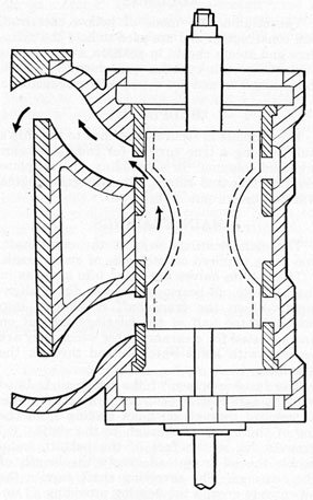
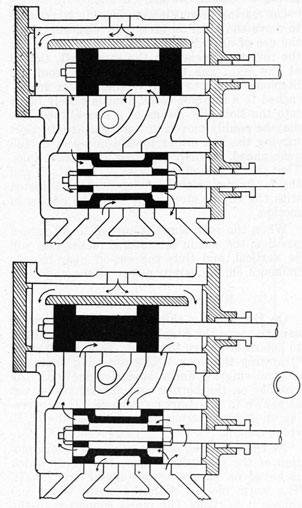
Differential Valve-As the reversing engine has only one eccentric, the reversing of it is made possible by using a differential valve for controlling the steam and exhaust to and from the steam chest. The differential valve is the top piston valve shown in the cross-sectional sketch.
In the first sketch the differential valve is moved to the right which allows the steam to flow by through the port to the engine steam chest, where the steam passes through the length of the hollow piston valve to the opposite
DIFFERENTIAL VALVE
end of the chest where it enters the right-hand end of the engine cylinder through the open port. This starts the engine rotating in a clockwise direction.
In the second sketch the differential valve has been moved to the left but the engine valve is in the same position. The steam now enters the engine steam chest from the opposite end of the differential steam chest and passes around the inside of the engine valve from where it flows through the port to the left end of the engine cylinder. This starts the engine turning in the opposite direction as shown by the arrow in the circle.
While the steam is entering one end of the cylinder, the spent steam is exhausting from the opposite end through the ports and valves as shown by the arrows.
The differential valve is moved back and forth by a lever.
Differential valves are also used to reverse steering engines and winches as will be brought out later in the manual.
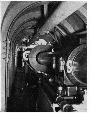
LINE SHAFT AND SPRING BEARINGS
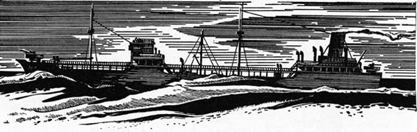
Except in oil tankers and ore carriers, most vessels have their engine and boiler rooms located amidships. This means that a long steel shaft, as shown in the shaft alley illustrated on page 67, is needed to connect the revolving crankshaft with the propeller. Several bearings known as spring bearings, marked (S), support this shaft at the necessary points along its length. A tunnel, known as the shaft alley, houses the line shaft, from the after bulkhead in the engine room to the afterend of the line shaft at the stern gland. The alley provides sufficient room for the oiler to walk alongside the revolving shaft so that he may feel and oil the spring bearings. Usually only the bottom half of these bearings is lined with babbitt metal, the top half being a cast iron shell which has a relatively large clearance between it and the shaft. The lubricating oil is poured in the top after the cover has been raised, and runs down around the shaft to form a film between the babbitt metal in the bottom half and the shaft.
The C-shaped objects around the line shaft are guards surrounding the couplings.
TAIL SHAFT AND PROPELLER
The last section of the line shaft is known as the tail shaft. It extends through the stern tube into the sea and on its end is secured
67
the propeller. The stern tube is fitted with lignum vitae wood bearings to support the tail shaft. The steel tail shaft is protected from the corrosive action of sea water by a bronze sleeve
SHAFT ALLEY
shrunk on around the outside of the shaft. As the bronze-covered shaft revolves in the wood bearings, sea water flowing in from the sea end of the tube acts as a lubricant. To prevent the sea from flooding the shaft alley and ship, a stuffing box packed with several turns of flax packing is provided at the forward or shaft alley end of the stern tube. When the ship is underway the gland should be slacked off just enough to permit a small stream of sea water to flow out of the stern tube into the shaft alley bilge, to insure that the bearing is being lubricated. It is very important that the outside of the stuffing box be felt by the oilers for overheating at each round, as the packing may overheat and burn up if too tight. Upon leaving dry dock, where the stuffing box has been repacked, an especially close watch should be kept.
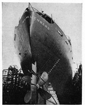
In this picture a propeller can be seen in place on a single-screw ship in dry dock. A propeller is simply a large screw which, when revolved in one direction, will screw itself forward
through the water, like a steel screw in wood, pushing the ship ahead of it. If revolved in the opposite direction it screws itself backward through the water, pulling the ship with it.
STERN OF LIBERTY SHIP
Propellers are usually made of bronze to resist corrosion and are secured to the end of the tailshaft with a tapered fit and large nut.
To do their best work, propellers must be designed to turn at relatively slow speeds, 100 R.P.M. or below. With the conventional type, reciprocating main engine, the propeller turns at the same speed as the engine, but with turbine engines which turn at several thousand R.P.M., it is necessary to reduce the speed between the turbine and the propeller.
When the ship is loaded, the propeller is well below the surface of the water, but when light it may break the surface when turning. Extreme care must be exercised when alongside the dock or when anchored that no obstructions, such as small craft, are near the propeller before moving it.
In heavy seas the propeller may frequently break water, causing the engine to race.
Also, in this picture may be seen the rudder for steering the ship and the depth markings in feet on the side of the hull.
68
69
70
71
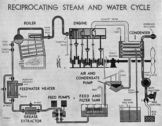
RECIPROCATING STEAM AND WATER CYCLE
MULTIPLE EXPANSION ENGINES
The single cylinder reciprocating steam engine used extensively to operate ship's auxiliaries would be too inefficient for propulsion. After the steam in the cylinder has expanded and pushed the piston there is considerable heat left in the exhausting steam. It is to put this to work that additional cylinders are added.
Compound Engine-A compound engine has two cylinders, the one in which the first expansion takes place being known as the "high pressure" cylinder, the other as the "low pressure" cylinder. To provide room for the expanded steam and to develop the same amount of power in both cylinders the "low pressure" one will have to be larger than the "high pressure." Compound engines are used mainly in towboats.
Triple Expansion Engines-In ocean going ships engines with at least three cylinders are used. These are known as triple expansion because the steam expands three times.
In the triple expansion engine used in the Liberty ship, a cross-section drawing of which is shown on page 70, the steam enters the H. P. (High Pressure) steam chest of the engine at about 220 pounds pressure where it is admitted to the cylinder by the H. P. piston type D slide valve. The steam expands in the cylinder, losing temperature, pressure dropping to about 75 pounds per square inch. It exhausts to the M. P. (Medium Pressure) valve chest and cylinder where it expands again, the pressure dropping to about 12 pounds per square inch at which pressure it exhausts into the L. P. (Low Pressure) valve chest and cylinder where it expands for the last time against the large L. P. piston. Equal power is developed in each cylinder. The steam upon exhausting from the L. P. cylinder enters the main condenser through the exhaust trunk. The vacuum of approximately 26 inches maintained in the condenser also is present in the exhaust trunk and in the L. P. cylinder on the exhaust
72
side of the piston. This adds considerably to the power of the engine.
Other multiple expansion engines are four cylinder triple expansion in which there are two smaller L. P. cylinders instead of one big one and quadruple expansion having four cylinders in which the steam expands.
THRUST BEARINGS
The propeller screwing itself forward through the water will push the tail shaft, line shaft and crankshaft forward through the ship, wrecking the engine unless the shaft is prevented from moving endwise. When the propeller is turning astern, it tends to pull the shafting out of the ship. To prevent this, the thrust bearing is installed on the line shaft just aft of the engine and as the tremendous thrust of the propeller is held in check at this point, the ship is actually pushed here. The thousands of pounds pressure exerted by the propeller create a terrific friction in the thrust bearing requiring excellent lubrication to prevent overheating.
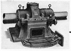
KINGSBURY THRUST BEARING HOUSING
Two types of thrust bearings are in service, the horseshoe or multi-collar, and the Kingsbury. The horseshoe once practically the only type used has been replaced in new construction for a number of years by the Kingsbury. In the horseshoe type, the shaft was made with several circular collars a few inches apart along the shaft. Fastened through the thrust bearing frame to the ship's hull, horseshoe shaped bearings are placed between the rotating shaft collars. As the propeller starts to thrust forward or backward, the shaft collars immediately come up against the babbitt face of the horseshoes which stop the forward or backward movement. Lubricating oil must be continually supplied between the face of the shaft collars
and horseshoe bearings. The base of the thrust bearing is filled with lubricating oil in which the shaft collars revolve carrying the oil upward between the collars and horseshoes. As the oil falls back into the base, it carries with it some of the friction heat. A sea water cooling coil running through the oil in the base carries a large portion of this heat away.
To help carry away the tremendous friction heat, sea water is pumped through the hollow shoes. The discharge side of the cooling water is open to view so that the oiler can readily see if any of the shoes should plug up. Sea water contains impurities which when heated tend to leave the water and cling to the inside of the horseshoes. By connecting a water or steam hose to the plugged shoe, it can usually be cleared. The horseshoes should be felt by the oiler at every round and the cooling water discharge from each shoe noted.
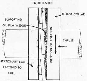
KINGSBURY THRUST BEARING
The principle of a Kingsbury thrust bearing is shown in the simple sketch. A single shaft collar pushes against several pivoted shoes which are held in place by a stationary seat fastened to the hull of the ship. When the shaft is revolved, the shoes pivot to allow the film of oil between the collar and the shoes to take the form of a wedge. The wedge of oil can withstand tremendous pressure without breaking down making it possible to operate a single collar. The entire bearing is encased in a housing, as may be seen in the picture. Lubrication is supplied by the rotating collar dipping in the oil sump.
Kingsbury type thrust bearings require much less space than horseshoe and are more efficient.
73
LUBRICATION
Friction is, and always will be, present in every moving machine, for it cannot be entirely eliminated.
Friction is that which resists the motion of either of two bodies when in contact with each other. Friction results in wear and power losses, therefore, there is a great necessity for reducing it as much as possible through the use of lubrication.
If two pieces of metal were polished to the highest degree possible and placed in contact, under a microscope, it would be found that the
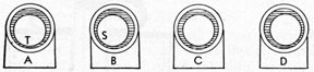
two surfaces were jagged. In the sketch is shown a journal in a bearing as it would appear greatly enlarged. In order to reduce friction between the surfaces, a lubricating oil or grease is used to separate the surfaces.
There are three kinds of friction that involve lubrication:
1. Rolling friction; the tire of an automobile on the road.
2. Sliding friction; a journal turning in a bearing.
74
3. Fluid friction; friction set up by the churning of the oil.
Lubrication problems are best understood by a thorough knowledge of its action. When good lubrication is obtained, there is formed in the bearing an oil film which separates the bearing
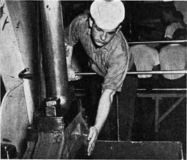
OILER FEELING CRANKPIN BEARING
surface and the journal of the rotating shaft. This prevents metallic contact. Then, the only friction involved is the fluid friction of the oil. This fluid friction varies with the viscosity of
OILER FEELING CRANKPIN BEARINGS
OILER FEELING ECCENTRICS
the oil, the temperature of the oil, the journal speed, and journal pressure.
The sketches of a journal in a bearing show the conditions existing under different circumstances. In (A) the journal is at rest and contacts the bearing at (T). In (B) the journal is just starting to turn and contact point moves to (S). As the journal turns, the oil film forms and lifts the journal in (C). (D) shows the position of journal in relation to bearing at full speed.
The sketches show the clearances exaggerated for simplicity.
Too much stress cannot be laid on the importance of proper lubrication of all units in any machinery plant. All rubbing surfaces should receive a steady and sufficient supply of oil of the proper quality at the proper temperatures. There is a byword around power plants that oil is cheaper than metal.
On heavy slow-speed engines, such as the reciprocating engine, the lubrication problem takes into consideration the one factor of separating the two rubbing surfaces, therefore, only a small amount of oil is required.
In high speed machines, such as turbines, the lubricating problem must not only consider separating rubbing surfaces, but the speed is so great that a large amount of fluid friction, caused by the churning of the oil, is created. This fluid friction generated heat must not remain in the bearing so that the heat is carried away with oil draining from the surfaces. For this reason the pressure lubricating system for turbines has been developed.
With the reciprocating engine the following bearings and sliding parts require lubrication:
Main Bearings
Eccentrics
Crankpin Bearings
Crosshead Bearings
Valve Gear Bearings
Link Blocks
Guides
Piston Rods
Piston and Valves
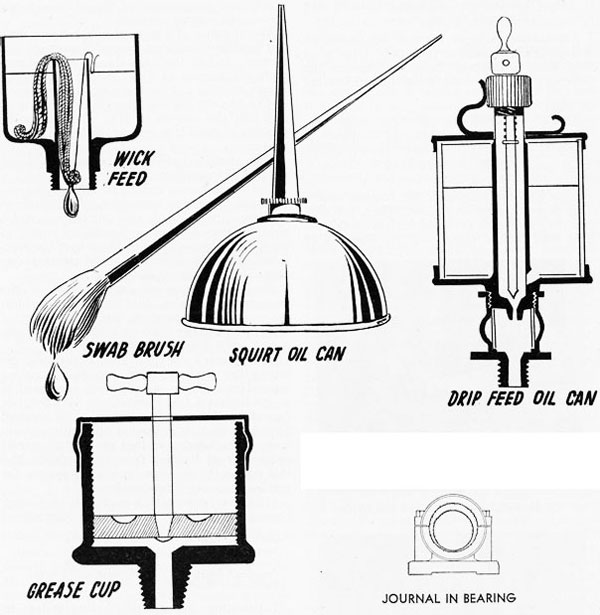
Lubricating oil specially compounded to readily emulsify with water is partially fed to the main bearings by wicks located in an oil box on top of each bearing. The oil box must be filled regularly and the wicks kept clean. Additional oil is supplied by hand with a squirt can. Partial lubrication is also supplied to the crankpin, crosshead bearings and guides from brass oil boxes on the side of the cylinders with syphon feed wicks and pipes leading to the oil cups on the individual bearings. Like the main bearings, the remainder of the oil is supplied by hand, the trick being to hit the moving oil cups
75
with the squirting oil from the can. The brass oil cups for the crankpin and crosshead bearings are located on the crosshead, being of good size and filled with horsehair to prevent the movement of the engine from throwing the oil out of the cup before it has a chance to run down into the bearing. The hair is held in place by small copper wire and must be cleaned frequently.
Small brass oil cups filled with horsehair are located on the eccentrics, various valve gear bearings, and air pump drag link and beam bearings. These bearings are usually oiled entirely by hand.
A metal comb attached to the bottom of the crosshead slipper dips into a trough or pan filled with oil and water at the bottom of the guide, carrying this lubrication up on the surface of the guide in addition to the gravity oil feed line.
Lubrication in the form of steam engine cylinder oil is supplied to the piston rods and valve stems by a long handled swabbing brush.
In engines using saturated steam, the particles of moisture in the steam plus what cylinder oil enters the cylinders and steam chests with the piston rods and valve stems are generally sufficient lubrication for the piston rings and valves. However, the newer type engines using superheated steam must have cylinder oil supplied to the valve chests and cylinders. A small mechanical pump forces the oil into the H. P. valve chest from where it travels with the steam through the engine to the various pistons and valves. Excessive lubrication to the cylinders greatly increases the possibility of oil entering the boilers and must be avoided.
RECIPROCATING ENGINE ATTACHMENTS
Drains for Cylinders and Steam Chests-To remove water from the steam chests and cylinders, formed when the steam comes in contact with the cold metal walls when warming up the engine, drain cocks or valves are installed on the bottom of each chest and cylinder. Reach rods are provided so that they may be opened and closed from the operating floor. The drains are piped to discharge into the main condenser where the vacuum speeds the removal of the water. Water may also carry over from the boilers into the cylinders when the ship is rolling heavily or the water level in the boilers is carried too high. Water in an engine cylinder is dangerous, as it will not compress when the piston approaches the head, resulting in severe damage to the engine in some cases. A slapping
sound in the cylinders of a moving engine is evidence of water and the drains should be opened at once.
Relief Valves-In an effort to prevent this damage, spring type relief valves are installed at the top and bottom of each cylinder. When the piston tries to compress the water between it and the head, excessive pressure is built up which opens the relief valve, allowing the water to squirt out into the engine room. Faith must not be placed in these as they cannot take care of a very large amount of water.
Throttle Valve-To start and stop the engine and control its speed, the throttle valve is installed in the steam line just outside the H. P. valve chest. It is usually a double seated, balanced valve making it easy to operate. The valve is controlled by either a hand wheel or lever located on the cylinder column at the operating platform. For a quick emergency stop, some engines are equipped with a butterfly valve between the throttle valve and the engine. This operates on the same principle as a damper in a stove pipe and is closed by pulling a lever. In heavy seas the propeller will sometimes come out of the water at frequent intervals which removes the load from the engine, allowing it to race. To prevent its possible destruction the engine must be immediately slowed down by closing the butterfly or throttle valve. This is known as standing a throttle watch.
By-pass Valves-When warming up a reciprocating engine, it is necessary to allow steam to enter the steam chests and cylinders for an hour or so before moving the engine. Without the engine moving, the steam entering through the throttle valve will not pass further than the H. P. cylinder. To supply steam to the M. P. and L. P. a by-pass steam line around the throttle valve is provided. A valve in the bypass line to each cylinder is provided with an extension rod to the operating floor. The bypass valves are also used when maneuvering, as it sometimes becomes necessary to push the H. P. crank off dead center before the engine can be started.
Jacking Gear-When making repairs or adjustments to the engine in port, it is necessary to turn the engine to a desired position in order to place a particular crosshead or crankpin in an accessible position for working. This is done with the jacking gear which is a small single cylinder steam engine fastened usually to the L. P. Column. A worm on the crankshaft of the jacking engine slowly turns a large worm
76
wheel secured to the main engine crankshaft. The jacking engine is usually reversible which allows the main engine to be jacked in either direction. Never attempt to do any work on the engine in port unless the jacking engine is engaged. The force of the current or tide against the propeller may cause the engine to roll over, crushing you.
Before turning steam on the main engine, the jacking worm must be disengaged from the worm gear or the jacking gear will be severely damaged when the engine starts.
Revolution Counter-In order to determine the number of revolutions the main engine is making per minute, R.P.M., a revolution counter is installed, usually on one of the columns. It operates on the principle of an automobile mileage counter and is operated by a lever from one of the crossheads.
Dependent Air and Condensate Pump-With many reciprocating engines the air and condensate pump is secured to the L. P. column and operated from the low pressure cylinder through a beam arrangement, one end of which is fastened by connecting rods, called drag links, to the L. P. crosshead and the other end in the same manner to the air pump. As the engine operates the beam acts like a see-saw pushing the pump up and down.
Balance Cylinders and Pistons-With engines having large heavy valves, a small cylinder known as a balance cylinder is quite often located on top of the steam chest covers, directly over the valves. A piston secured to the top of the valves by a short rod is fitted inside the cylinder. The top of the balance cylinder is connected by a pipe line to the main condenser. When in operation the pressure in the steam
chest pushing up on the bottom of the balance piston plus the vacuum sucking upward on the top combines to produce sufficient lifting force to remove a portion of the valve weight from the eccentric.
WARMING UP MAIN ENGINE
When preparing a reciprocating engine to get underway the first step is to inspect the engine carefully to make sure nothing has been left in the crankpits and that the engine is generally clear.
The jacking gear worm is next removed.
The main condenser circulating pump is then started up after opening the main injection valve and overboard discharge valve.
Steam and exhaust valves to the reversing engine are opened.
Throttle drain valve is opened.
Main stop on boiler is cracked, allowing steam to flow through main steam line to throttle valve.
Throttle valve is cracked allowing sufficient steam to enter H. P. steam chest and cylinder to warm them up but not enough to move the piston.
M. P. and L. P. by-pass valves are opened sufficiently to warm up these cylinders.
While the cylinders are being warmed the lubricating oil boxes on the various bearings should be filled to proper level and the wick feeds inserted. Lubricating oil should be poured
77
in all oil cups before the engine is moved. Likewise the level of oil in the thrust bearing should be checked and the spring bearings on the line shaft oiled. The eccentric dip pans should be filled with fresh water to proper level.
REVERSING MAIN ENGINE
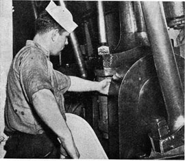
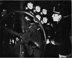
In the picture the Chief Engineer is maneuvering the main engine. His left hand is controlling the reversing engine and his right the by-pass valves. He is watching the Stephenson valve links, so that when they are in the astern position, he may stop the reversing engine. This is done by moving the differential valve control lever to center position.
The engine must not be moved until permission has been secured from the officer in charge on the bridge and the cylinders have been warmed for an hour or two. Then the main stop valve may be opened wide and the engine rocked carefully ahead and astern being careful not
to make a full stroke until certain all water has been worked out of the cylinders. The engine may then be operated very slowly in the direction permitted by the bridge officer until it is thoroughly warmed up.
MANEUVERING MAIN ENGINE
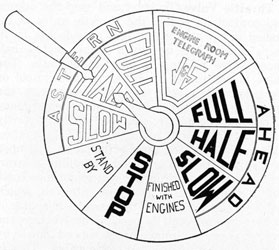
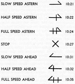
When docking or undocking a ship or moving in congested waters the bridge officer depends upon immediate compliance with his orders as to direction and speed with which the main engine turns. Delay in reversing the engine for example may cause a serious collision. The engine direction orders are relayed from the ship's bridge to the engine room by the engine telegraph. The sketch of the telegraph is shown. The center hand is turned from the bridge to point to the desired direction the engine is to turn and also the speed. As the hand turns a bell rings loudly to attract attention. Immediately the signal is received it is answered by moving the outside handle to point to the same position as the center pointer. The engine is then reversed, stopped or operated as indicated. The signals are known as bells and are written down usually in a bell book and rough log showing the time received using the symbols shown on opposite page.
When maneuvering, the engine drains are usually left open until underway, although it is sometimes safe to close the H. P. drains when the engine is moving.
As soon as the engine is required to operate fairly consistently the cooling water service should be turned on the thrust bearing, main bearings and guides.
78
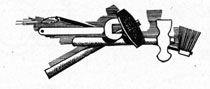
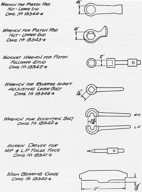
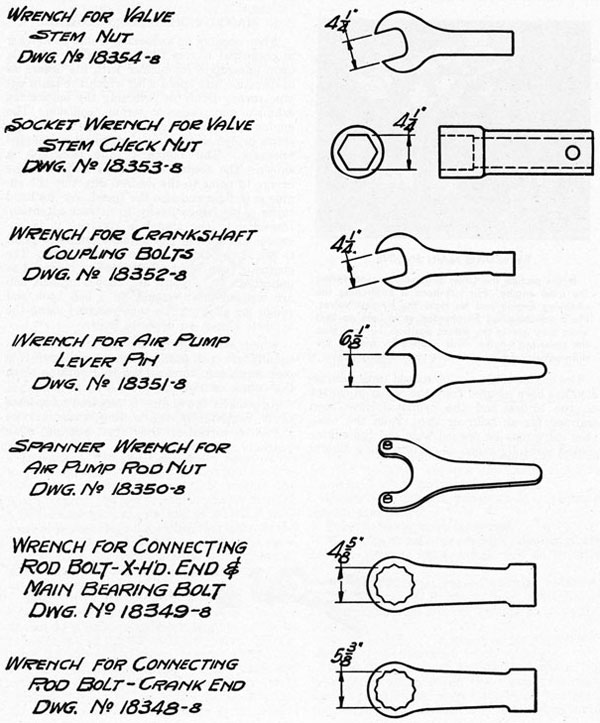
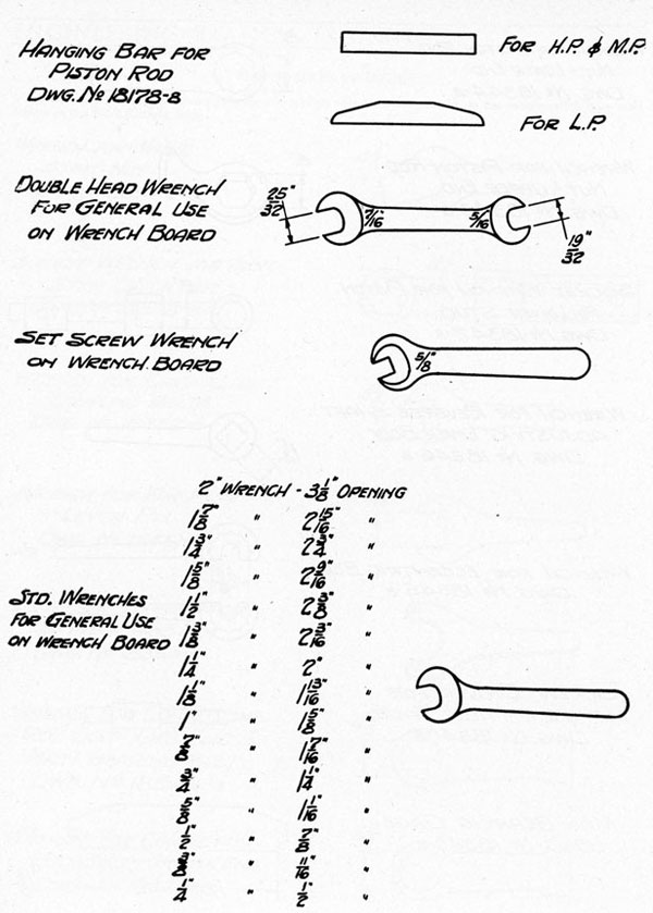
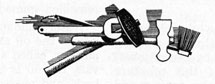
ENGINE ROOM WRENCHES
The following wrenches are principally used in making adjustments or repairs on the reciprocating type main engine of the EC-2 (Liberty Ship).
79
80
81
STEAM TURBINES
PRINCIPLE
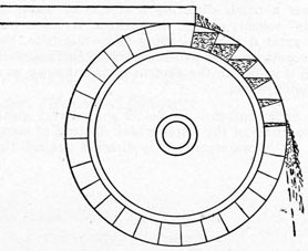
In order to understand the principle upon which the steam turbine operates, let us first consider the water wheel. In the old type water wheel, the water was piped to the top of a wooden wheel containing blades or buckets. The water filled the buckets and thus turned the wheel, causing the water to spill when the buckets reached the bottom. This is known as an overshot water wheel and is shown in the sketch on the following page.
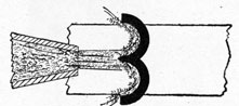
A wheel built to make use of water flowing from a higher level, or under greater pressure, uses a nozzle directing a stream of water at high velocity against the buckets. As there was a great deal of splashing from this type, the buckets are made with a curving surface, such as is shown in the sketch. This is known as a Pelton wheel.
Steam turbines use blades shaped very much like those of the water wheel. Instead of using a jet of water, steam is directed against the
MODEL OF G-E CROSS-COMPOUND GEARED MARINE STEAM TURBINE
blades by a nozzle. The nozzle is so designed that it converts the pressure of the steam into velocity. The steam is usually directed from the side of the wheel against the curved blades.
OVERSHOT WATERWHEEL
TYPES OF TURBINES
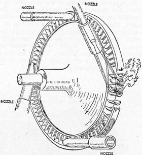
Impulse Turbines-Several nozzles are used to direct and give velocity to the steam. The blades convert the velocity of the steam into a rotary motion. This type of turbine is known as an impulse turbine due to the fact that most of the velocity of the steam is converted into rotary motion by the impact or impulse force of the steam on the blades.
PELTON WHEEL
A sketch of the impulse turbine is shown.
The sketch is a single impulse wheel with four nozzles. In the nozzles, steam expands and its pressure is converted to velocity so that the steam leaving the nozzles strikes the plates at high velocity causing the wheel to rotate.
The impulse turbine is built in single stages, as the one described, or in multi-stage, having two or more simple turbines on the same shaft.
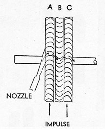
The second sketch shows the position of nozzle, moving blades, stationary blades and the second row of moving blades in a Curtis stage of an impulse turbine. The steam is expanded
in the nozzle, gives up part of its energy in pushing the row of blades (A), is redirected in the second row of moving blades by the stationary row of blades (B). The steam gives
SIMPLE IMPULSE TURBINE
up more of its velocity in the row of moving blades (C). The stationary row of blades is used to reverse the direction of the steam flow.
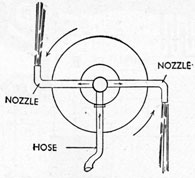
Reaction Turbines-Another type of turbine is shown as the reaction turbine. The third sketch represents a lawn sprinkler using the reaction principle to cause it to rotate. The water is led to the sprinkler through a hose.
83
The water flows up the vertical pipe into the two horizontal bent arms which end in nozzles. The water is discharged from each nozzle at an
REACTION
increased velocity, and as it leaves, reacts or kicks back on the nozzle, giving a rotating motion to the arms in an opposite direction to the stream of water. It is this reaction force alone that causes rotation of the sprinkler.
The reaction turbine uses a set of stationary
reaction shown on turbine
curved blades or vanes which direct the steam into a set of blades mounted on a wheel or drum. The steam expands in these blades, leaving at a higher velocity than that at which it entered, thus kicking the blades around in a rotary path. A reaction turbine contains many rows of stationary and moving blades, each set being known as a stage and the steam being expanded slightly in each row.
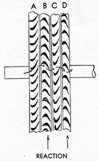
The fourth sketch shows the blading of a reaction turbine showing two stages. The steam enters the stationary blades (A) which direct it into the first row of moving blades (B). The steam pressure is decreased and the velocity slightly increased in the stationary blades. Thus some impulse is used in this turbine. In the moving blades the steam expands, increases in velocity in leaving and tends to turn the blades by reaction. A second row of stationary blades (C) redirects steam into the second row of moving blades (D), etc., where the action is repeated.
Neither the impulse nor the reaction turbine is caused to rotate by one principle alone, but the impulse turbine has a small amount of reaction involved, and the reaction turbine, a small amount of impulse involved.
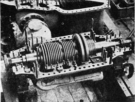
Some turbines consist of one rotor in one casing, in which case it is known as a complete expansion turbine. However, to reduce the size
WESTINGHOUSE TURBINE WITH TOP HALF OF CASING REMOVED
of the plant where higher pressures are used, the turbine is compounded; that is, after the steam passes through one turbine, it is led to another turbine. The first turbine is known as the high pressure and the second as the low pressure. In most cases, the two turbines are placed side by side and are referred to as a cross-compound unit. There are some installations where expansion of the steam is done in three turbines, this being known as a triple-expansion turbine.
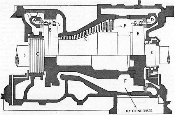
The sketch shows a complete expansion turbine which has been used in marine practice. The turbine blading is partly of the impulse, and partly of the reaction type. The steam
84
COMPLETE IMPULSE-REACTION TURBINE
enters the nozzle chamber (A) and passes through nozzles where it expands somewhat and increases velocity. It then passes through a Curtis stage at (B) consisting of two rows of moving blades separated by a row of stationary blades. After passing through these blades, the steam passes through 21 moving rows of reaction blading (C), together with the same number of stationary blades. The exhaust is taken from (F) and passes to the condenser. This action of the steam drives the rotor shaft (S) in the ahead direction.
Turbines have the distinct disadvantage in that they cannot run backwards. Because it is necessary for vessels to maneuver astern as well as ahead, there is installed a separate turbine of low power for running astern. It operates under high steam pressure, and is located in the same casing of a complete expansion turbine, or in the low pressure casing of a compounded unit.
Because it is imperative that steam is not admitted to the astern turbine while steam is on the ahead, or vice versa, some type of guarding mechanism is supplied at the throttle valves so that while one is open, the other cannot be opened.
In the sketch of the complete expansion turbine the astern turbine (E) consists of a Curtis stage and takes steam from the nozzle chamber (D). The steam pressure is supplied to (D) when running astern as supplied to (A) when running ahead. Marine turbines have comparatively little backing power.
REDUCTION GEARS
There is a great deal of theory attached to the design and construction of a steam turbine, which will not be gone into at this time. However, it might be said that for theoretical reasons, it is impossible to get any form of efficiency from a slow speed turbine unless of tremendous size. So in marine practice, where the saving of space and weight is an asset, turbines are small in size and operate at very high speed, 2,500 to 6,000 R.P.M. This high speed is contrary to the requirements of a propeller for good efficiency. A propeller must turn at relatively low speeds (80-100) R.P.M., therefore, the high speed of the turbines must be reduced to the low speed of the propeller. This is done in one of two ways; either mechanically with reduction gears, or electrically. The electric
85
method is known as turbo-electric, and in this system the turbine is directly connected to a generator and the high speed generator drives a synchronous or induction motor at low speed, which in turn drives the propeller. In the majority of installations, the speed reduction is effected mechanically, or with reduction gears.
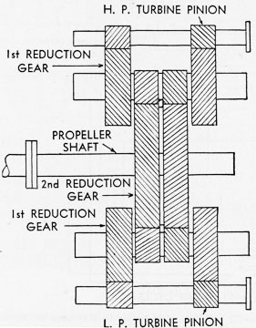
DOUBLE REDUCTION GEARS
There is a small pinion on the turbine shaft which meshes with a larger gear to effect one speed reduction. If the speed is still sufficiently high to necessitate further reduction, there is a pinion on the shaft of this gear which meshes with another larger gear to effect a second reduction. This latter type, known as double reduction gears, is very frequently used.
The sketch shown is an arrangement of one type of double-reduction gear. Gear teeth are not cut straight across the gear, but are either cut spirally, known as helical gear teeth, or are cut at opposing angles, known as herringbone gear teeth.
SHAFT PACKING
When the rotor extends through the end of the turbine casing, steam is prevented from leaking out and air from leaking into the casing by glands. These consist of labyrinth packing which consists of a series of rows of metallic
strips through which the steam is throttled several times to greatly reduce the leakage pressure. Carbon rings around the shaft and water seals are also used.
SPEED GOVERNOR
Every turbine has a maximum safe speed limit which must not be exceeded, otherwise the blade wheels may explode from the excessive centrifugal force set up and destroy the turbine.
TURBINE LUBE-OIL PRESSURE SYSTEM
To limit the speed to a safe R.P.M., an automatic speed governor is installed on every turbine installation. It is a vitally important piece of equipment and must not be tampered with. One type of governor uses revolving weights which swing out by centrifugal force from a center shaft as the speed of the turbine increases. As the weights swing out they act on a series of levers and rods which close in on the steam governor valve, which limits the steam entering the turbine and so the speed.
86
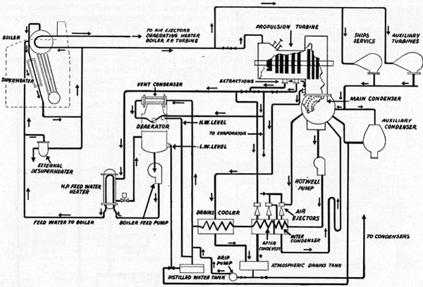
MODERN TURBINE STEAM AND WATER CYCLE
This modern installation is typical of those used on the T-2 tankers and is similar to that used on Victory and C-type ships. The boilers operate at 450 lbs. per square inch and the steam temperature at the turbine throttle valve is about 750° F. The high efficiency of the steam generating plant is dependent in part upon the high temperature of the feedwater as it enters the boiler.
The method of feedwater heating shown here consists of bleeding high temperature steam from various extraction points on the turbine and using this steam to heat the feedwater for the boiler. Such a system is capable of more than a 10 per cent saving in fuel consumption because the steam used to heat the feed-water has already been used to turn the turbine and move the ship.
As with all turbine propulsion plants the proper amount of vacuum must be maintained in the main condenser if full efficiency and power is to be realized. Any loss of vacuum causes the turbine rotor to slow down even though the same amount of steam is entering the turbine.
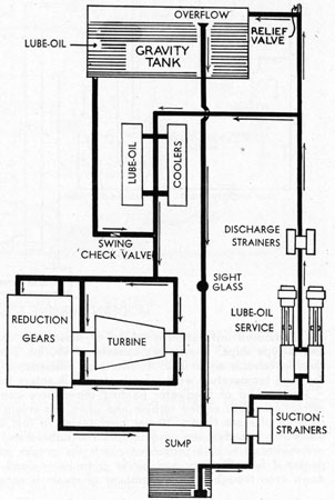
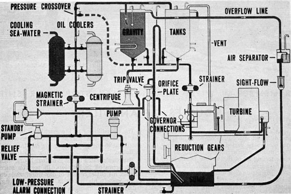
LUBRICATION
The lubrication of turbines is usually accomplished by the circulation of oil under pressure. The oil is taken from a sump tank and through suction strainers by a lube-oil service pump. The sump tank is equipped with a float to show the level of the oil in the tank. The suction strainers are used to remove any solid particles that might damage the pump. Suction strainers are installed in duplicate, or are duplex, so one may be in service while the other is cleaned.
At least two Tube service pumps are installed
in the system. Thus, one is a stand-by pump, while the other is in service. The lube-oil service pump discharges through duplex discharge strainers of fine mesh, where any foreign solid matter which passed through the suction strainers is removed.
The oil then flows through lube-oil coolers where heat is removed from the oil by passing over coils through which sea water is circulated. The circulating water is usually taken from the discharge of the sanitary pump, although a pump to be used just for this purpose may be installed.
87
TURBINE LUBRICATION-GRAVITY TYPE SYSTEM
From the lube-oil coolers the oil flows to each of the bearings of the turbine and to the reduction gears. The amount of oil supplied to the bearings must be sufficient to cool as well as lubricate them. The oil supplied to the reduction gears flows to the gear shaft bearings and between the gear teeth. From the turbine bearings the oil drains out to the gear casing where the oil from the gears and the bearings drains to the sump tank to be used over again.
Some of the oil pumped from the sump is discharged through a relief valve into the lubeoil service tank, thus keeping the service tank full, the excess overflowing through the overflow line, passing down to the sump tank by way of a sight glass where the flow of oil can be observed.
A connection is made from the lube-oil service tank to the bearings and gears through a swing check valve that is kept closed by the oil pressure of the service pump. If this pressure should fail, the oil in the service tank would flow to the bearings to supply the necessary
lubrication, until the turbine can be stopped. A low pressure alarm is installed to give warning should the oil pressure fall below a safe limit.
Pressure gages are installed on each bearing and on the lines to the gears to show the pressure of oil supplied to them.
Thermometers are installed at various points of the system to show the temperature of the oil entering the cooler, leaving the cooler, and the oil leaving each bearing.
The operating temperatures of the bearings can not be definitely stated, but in most cases should never exceed 130° F., and should never be carried below 90° F. A rise in bearing temperature above normal definitely indicates trouble, which should, of course, be found and remedied immediately.
Water, sludge, and sediment which accumulate in the oil are removed by a centrifugal oil purifier, called a centrifuge. At frequent intervals, the oil is taken from the service or sump tank, and passed through the centrifuge, from which the cleaned oil returns to the sump tank.
88
REMEMBER-A WIPED BEARING MAY STOP YOUR SHIP
DUTIES OF AN OILER
At sea the main engine usually turns at a steady speed although in convoys the speed will quite often be varied from time to time. The oiler makes regular rounds usually every half hour feeling all of the various bearings on the main engine and oiling them. He also must swab the piston rods and valve stems. He also feels of the thrust bearing and travels down the shaft alley feeling and oiling the spring bearings and feeling the stern gland and looking to see if sea water is running through. In between his regular rounds the oiler checks the engine room auxiliaries, refrigerating system and steering engine. He should know how to stop the main engine should it become necessary and the engineer were absent.
It is the oiler's duty to learn everything possible in connection with the operation of the vessel's power plant, because when opportunity comes for advancement he will be able to qualify for the position of watch engineer.
All oilers should thoroughly understand the operation of the different types of lubricating oil pressure and gravity systems for turbine lubrication.
The actual oiling of the machinery takes up but little of the oiler's time. However, he should have the plant under his constant surveillance.
The oiler's watch at sea is of four hours, with eight hours off in between. In port on some vessels, his duties consist of day work, while on other vessels his watch is eight hours long, with sixteen hours off in between.
During his watch, the oiler is probably called upon to do one or all of the following. Pump out the bilges, pump up fresh water or ballast tanks, keep an eye on the water level in the boilers and on the fireman, take temperatures of the stack, sea water, filter box, and feedwater for entrance into the logbook, keep oil wiped up off the floor plates and gratings, and on some ships he has a station to keep clean.
In port his work consists mainly of oiling the auxiliaries, and in assisting in the maintenance and repair of the plant. He may be called upon to oil and watch the cargo winches during the night if the cargo is being worked at that time.
His is a responsible job; his negligence may result in damage to machinery to the extent of thousands of dollars.