Castings are made by pouring molten metal into refractory molds and allowing the metal to solidify. The solidified metal will retain the shape of the mold cavity and can be removed from the mold when the metal is solid. A mold is made by shaping a suitable sand mixture around a pattern of the desired form. A metal or wood box (flask) is used to retain the sand. The pattern is then removed from the sand, leaving a cavity in the sand into which the molten metal can be poured.
The molder's skill is the basic skill of the foundry. He must know how to prepare molds with the following characteristics:
1. Strong enough to hold the weight of the metal.
2. Resistant to the cutting action of the rapidly moving metal during pouring.
3. Generate a minimum amount of gas when filled with molten metal.
4. Constructed so that any gases formed can pass through the body of the mold itself rather than penetrate the metal.
5. Refractory enough to withstand the high temperature of the metal, so it will strip away cleanly from the casting after cooling.
6. Collapsible enough to permit the casting to contract after solidification.
The refractory material normally used by foundries is silica sand bonded with clay. The material usually provided for the variety of castings made aboard repair ships is a washed and graded silica sand mixed with clay and cereal bond as described in Chapter 4, "Sands for Molds and Cores."
MOLDING TOOLS AND ACCESSORIES
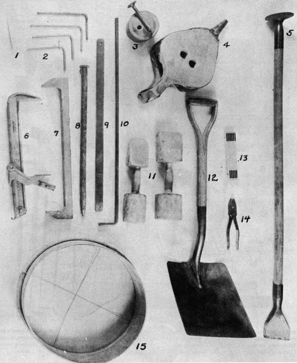
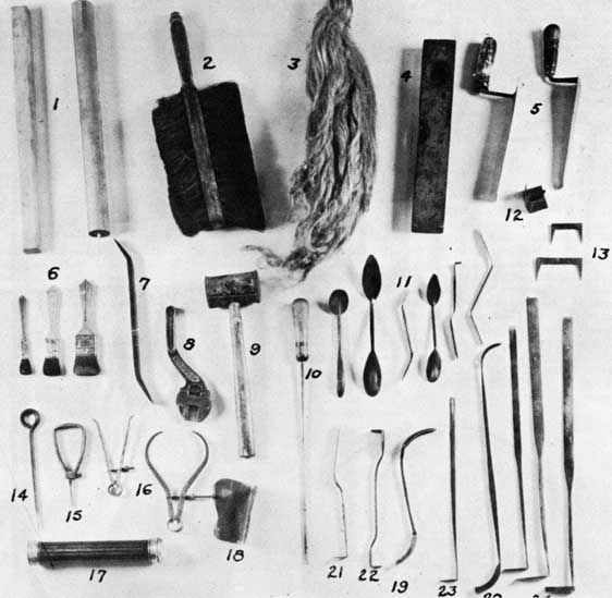
The basic molding tools and accessories used by the molder and coremaker are described below and shown in figures 71 and 72.
FLASKS
Flasks are wood or metal frames in which the mold is made. They must be rigid so that distortion does not take place during ramming of the mold or during handling. They must also resist the pressure of the molten metal
during casting. The pins and fittings should be continually checked for wear and misalignment to avoid mismatched or shifted molds.
The use of steel flasks is preferred, but cases will arise requiring a size of flask not available. Under such circumstances, a flask may be constructed of wood. It should be husky enough to stand wear and tear. If it is planned to use the flask for several molds, allowance should be made for some burning of the wood, which will often occur when the metal is poured.
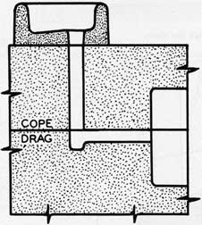
A flask is made of two principal parts, the cope (top section) and the drag (bottom section). When more than two sections of a flask are necessary, either because of the size or design of the casting, intermediate flask sections, known as cheeks, are used.
HAND TOOLS
RIDDLES are used for sifting the sand over the surfaces of the pattern when starting a mold. The size of the riddle is given by the number of meshes to the inch. A No. 8 riddle has eight meshes per inch, a No. 4 riddle has four meshes per inch, etc. The particular riddle used depends on the kind and character of casting to be made; castings with fine surface detail require finer sand and a finer riddle.
RAMMERS are used for tamping the sand around the pattern in the flask. For the heavier class of molding, they are made of iron. Sometimes they are made with a wooden handle with a cast iron butt on one end and a cast iron peen on the other. The small rammers used in bench work are usually made of maple, although sometimes they are made of cast iron or aluminum.
STRIKES are used to scrape the extra sand from the top of the cope or drag after ramming. They are usually a thin strip of metal or wood. They should have one straight edge and should be light but sturdy.
CLAMPS are used for holding together the cope and drag of the completed mold or for clamping together the mold-board and the bottom-board on either side of the drag when the latter is rolled over. They are of many styles and sizes. Some are adjustable and are tightened on the flask by means of a lever. Other types use wedges to secure them on the flask. The WEDGES are usually of soft wood, but for the heavier work are either of hard wood or iron.
62
BELLOWS are used to blow excess parting materials from the pattern and also to blow loose sand and dirt from the mold cavity. Compressed air hoses have almost replaced bellows for this purpose.
TROWELS are of many different styles and sizes to suit the individual taste of the molder and the particular requirements of the job. The trowel is used for making joints and for finishing, smoothing, and slicking the flat surfaces of the mold.
VENTS - Thin, rigid steel strips are used for making vents. Hacksaw blades are suitable for this purpose. Rods are also used for vents but they often cause a shrinkage depression at their base on the casting.
BOSHES or SWABS are made of hemp, tasselled to a point at one end and bound with twine at the other to hold it together. They are used for placing a small amount of water on the sand around the edge of the pattern before the pattern is rapped for drawing from the mold. Bushes will hold considerable water and the amount which they deliver to the sand can be regulated by the pressure the molder applies when squeezing them. Boshes are also used to apply wet blacking to dry-sand molds when they are to be blacked before the mold is dried.
SOFT BRUSHES are used to brush the pattern and the joint of the mold. The hard brush is used to spread beeswax or tallow on metal patterns and to brush and clean out between the teeth of gears and similar patterns.
CAMEL'S HAIR BRUSHES are used to brush dry blacking on the face of the mold.
RAPPING and CLAMPING BARS are usually bars of steel about 3/4 inch in diameter and 2 feet long. They are pointed at one end to enter rapping plates in a pattern and are flattened and turned up at the other end for convenience in tightening clamps on a flask.
DRAW SCREWS are eye-bolts threaded on one end. They are used for drawing large wooden patterns from the sand by screwing into holes drilled for that purpose in the rapping plate. They are also used for drawing metal patterns where pointed spikes could not be used.
DRAW SPIKES are steel rods which are sharpened at one end for driving into a wooden pattern to rap and draw it and are principally used in bench work for drawing small patterns.
LIFTERS are used for removing loose sand from deep cavities in molds. They are of different lengths and sizes, one end being turned at right angles to the stem; this portion is called
the heel. The straight, flattened portion is known as the blade and is used to slick the sides of the mold where they cannot be reached by the trowel or slicker. The heel is also used to slick the bottom of deep recesses after the sand has been removed.
SLICKERS are formed with blades of varying widths, sometimes with one end of the tool turned to form a heel somewhat similar to the lifter. It is used for lifting loose sand from shallow parts of the mold, for patching, and to form corners to the proper shape. This tool is widely used by molders.
SPOON SLICKERS have spoon-shaped ends and are used to slick rounded surfaces in a mold. They are usually made with one end larger than the other.
The DOUBLE ENDER has a slicker at one end and a spoon at the other. They are usually made to the molder's order and are used on small molds.
CORNER TOOLS are used to slick the corners of molds where a slicker or the heel of a lifter is not satisfactory. Corner tools are made with different angles for special work.
Various specialized tools such as flange tools, pipe tools, and hub tools are also used.
WOODEN GATE-PINS or SPRUES are round tapered pins used to form the sprue or down-gate through which metal is poured into the mold. The size depends on the size of the mold.
GATE CUTTERS are pieces of sheet brass bent to a semicircle on one edge. They are used to cut the ingate in the drag leading from the base of the sprue to the mold cavity.
SPRUE CUTTERS are cylindrical metal tubes used to cut the sprue in the cope when the sprue-stick is not used. Tapered sprue cutters are available for making the more desirable tapered sprue. They must be pressed down from the cope side before stripping the mold from the pattern.
CALIPERS are used more often by the core maker than the molder. The molder uses them to verify the sizes of cores in order to insure proper fit in the core print and also to obtain the length of smaller cores. The calipers in this case are set at the proper dimension and the core filed to fit. This is important in dry-sand work to prevent crushing of the mold if the core is too large when the mold is closed.
CUTTING NIPPERS are used to cut small wires to the desired length for use in cores or molds.
63
FACING NAILS
Facing nails are used: (1) to reinforce mold surfaces and to prevent washing of the mold face, (2) to mechanically lock the sand on the face with that deeper in the body of the mold, and (3) to act as a means for slightly accelerating solidification at internal corner s of the casting. These nails are similar to "roofing nails," having a flat, thin head of large diameter and shanks of various lengths. Caution must be exercised to see that no galvanized, rusty, oily, or dirty nails are used. The use of anything but clean dry nails will result in defective castings.
GAGGERS
Gaggers are used to give support to hanging masses of sand which would break under their own weight unless they were supported. Gaggers should be cleaned and are coated with clay before use to provide a better bond with the sand. Care must be taken in the placing of gaggers in the mold so that they are not too close to a mold surface, where they would cause a chilling of the metal where it is not wanted. Many times, a casting defect can be traced to a gagger located too near to a mold surface.
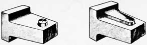
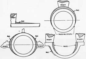
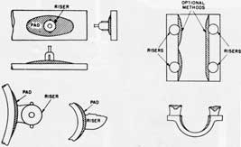
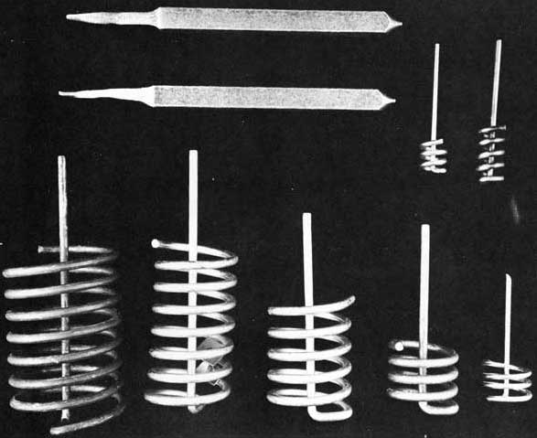
CHAPLETS
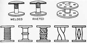
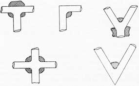
Chaplets are metal supports used to hold a core in place when core prints are inadequate. They are too often used to compensate for poor design, improper pattern construction, or bad core practice. In all castings (especially in pressure castings), chaplets are a continual source of trouble and should be avoided whenever possible. Figures 73, 74, and 75 show typical chaplets. It is absolutely necessary that they be clean. Rust, oil, grease, moisture, or even finger marks, cause poor fusion or porosity. Sandblasting immediately before use is a good practice if no other protection is used. Copper and nickel plating is a good method of protecting chaplets from rusting but does not eliminate the need for absolute cleanliness. Their size must bear a direct relationship to the type and section of metal in which they are to be used. Soft-steel chaplets are used in iron and steel, and copper chaplets in brass and bronze castings. Chaplets should be the same composition as the casting, if possible. The strength of the chaplet must be enough to carry the weight of the core until sufficient metal has solidified to provide the required strength, but it should be no heavier than necessary. The use of an oversize chaplet results in poor fusion and often causes cracks in the casting. A chaplet which can be made in the machine shop for emergency use is shown in figure 76. Chaplets should not have any sharp, internal corners because metal will not fill a sharp internal groove.
It is well to consider the forces which a chaplet must resist. In all metals except aluminum and the light alloys, a core tends to float
when molten metal is poured into the mold. It is buoyed up by a force equal to the weight of the displaced molten metal. A core with dimensions of 12 inches by 12 inches by 12 inches, or one cubic foot, will weigh approximately 100 pounds. Immersed in molten gray iron, which weighs 450 pounds per cubic foot, the core will tend to remain in place until it has displaced 100 pounds of iron, and then it will tend to float. In order to keep it submerged (displacing 450 pounds of cast iron) it will be necessary to exert 350 pounds of force on it (450 - 100 = 350). It takes no more force to keep it submerged at greater depths than just below the surface. A greater head does not increase the lifting effect, although it does increase the pressure on the core.
The ratio of 100 to 350, or 1 to 3.5, holds good for cores of any size, so we can make the rule that the force resulting from the tendency of a sand core to lift in cast iron is roughly 3.5 times its weight; for steel, 3.9 times; for copper, 4.5 times; etc.
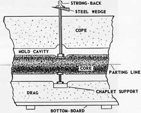
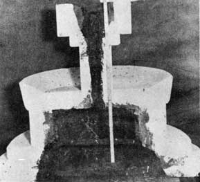
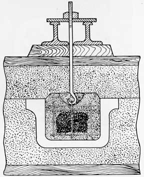
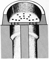
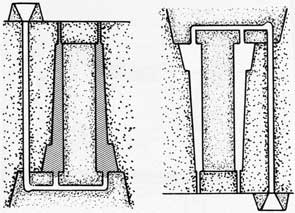
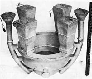
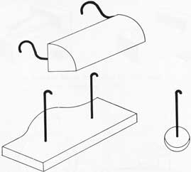
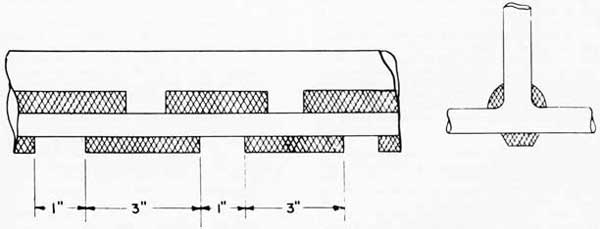
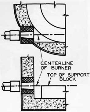
Where chaplets are used on large cores with extensive surface areas exposed to the metal, the usual practice is to use ordinary chaplets in the drag (since they are only required to hold the core in place until the metal is poured around them) and to use stem chaplets in the cope. Stem chaplets, instead of bearing on the mold face, pass through the mold body and are brought to bear against a support placed across the top of the flask. They are thus able to withstand very high forces, such as imposed when large cores tend to float on the metal. Figure 77 illustrates this method. It also shows a useful method for increasing the load-carrying ability of the green sand mold. A dry-sand core is used as a chaplet support in the mold. A dried oil sand core will safely support a load of 70 to 90 p.s.i. while the strength of green sand is 5 or 6 p.s.i.
Metal wedges or shims must be used to hold the stem chaplet down because the force of the molten metal acting on the core and transmitted through the stem of the chaplet will force it into a wooden wedge and thus allow the core to rise.
Table 19 for calculating the load-carrying capacity of chaplets of various sizes is given below.
TABLE 19. CHAPLET LOAD-CARRYING CAPACITIES
Double Head
Stem Chaplet
Diameter of Stem, inch
Size of Square Head, inch
Safe Load lbs
Diameter of Head, inch
Thin Metal Section, lbs
Heavy Metal Section, lbs
3/16
3/4
45
3/4
45
22
3/8
1-1/2
180
1-1/4
180
90
5/8
2-1/2
500
1-3/4
500
250
64
CHILLS
A detailed description of the use of chills will be found in Chapter 7, "Gates, Risers, and Chills."
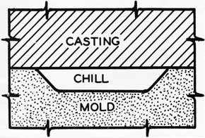
Chills used in making molds are internal chills and external chills. Internal chills are set so they project into the mold cavity. They are expected to fuse with the solidifying metal and become a part of the casting. Extreme care should be taken to make sure the chills are clean. Any grease, finger marks, film, or dirt will prevent good fusion between the chill and the casting. External chills are rammed up with the mold to anchor them firmly in the sand. They also should be rust free and clean when used without special treatment. Many times, when external chills fuse to a casting, the condition can be overcome by coating the chill surface with a thin coat of shellac, or other adhesive material, applying a very thin layer of fine, dry sand, and then drying the chill to drive off any moisture. Many commercial chill coating materials are available also. Torch drying of coated chills in the mold should be avoided because moisture from the flame will condense on the chill. Moisture will condense on cold chills in green sand molds if the molds are closed and allowed to stand for an appreciable time before pouring.
CLAMPS AND WEIGHTS
Clamps and weights are used to hold the cope and drag sections of a mold together and to prevent lifting of the cope by the force of the molten metal. It is safe practice to use a weight on small molds, but when the molds are of considerable size, both weights and clamps should be used. The use of insufficient weights is a common cause of defective castings.
TYPES OF MOLDS
The types of molds which are made aboard repair ships are (1) green-sand molds, (2) dry-sand molds, and (3) skin-dried molds. These three types of molds differ mainly in their sand mixture content.
GREEN-SAND MOLDS
Molds made from tempered sand (see chapter on foundry terminology) and not given any further treatment are called green-sand molds. Green-sand molds are used for normal foundry work aboard ship. They have the necessary green strength and other properties which make them suitable for a great variety of castings. Green sand gives less resistance to contraction of a casting than does dry sand, and thereby tends to prevent hot cracks in the casting. Green-sand molds are the easiest to make.
DRY-SAND MOLDS
Dry-sand molds, as the name implies, are molds made with tempered sand and then thoroughly dried by baking. Dry-sand molds are used when a mold of high strength is needed, or when low moisture content is important. Dry-sand molds are not recommended for complicated castings unless special care is taken to obtain sand mixtures which will give good collapsibility, so as to prevent hot cracks or tears.
SKIN-DRIED MOLDS
Skin-dried molds are green-sand molds which have been dried only on the mold surface by the use of a torch or some other source of heat. Skin-dried molds are used where a mold surface low in moisture content is necessary. The mold surface is usually sprayed with additional special binding materials and then dried by the use of a torch. This type of mold combines the firm sand face obtained from a dry-sand mold with the collapsibility of a green-sand mold in the backing sand. In general the sand used for skin-dried molds has a moisture content higher than for a green-sand mold and dry sand molds require a still higher original moisture content.
MOLDING LOOSE-PIECE PATTERNS
Loose-piece patterns are in one piece or are split to make molding easier. Molding with a split pattern will be described here. Molding with a single-piece pattern (and the use of broken parts) usually involves the cutting of a parting line and will be described under the section, "False-Cope Molding," later in this chapter.
In making a mold, a flask should be selected so that sufficient room is allowed between the pattern and flask for risers and the gating system. There must also be enough space over and under the pattern to prevent any break-outs of the metal during pouring or straining of the mold. Many castings are lost, or require extra cleaning, and many injuries to personnel are caused by the use of undersized flasks. It is better to err on the side of safety and choose too large a flask, rather than to use a flask that is too small. In addition to the safety factor, an undersized flask makes positioning of the gages and risers difficult. Gates and risers placed too close to a steel flask will be chilled by the flask and will not perform their function properly. Safe practice in the selection of a flask is shown in figure 78.
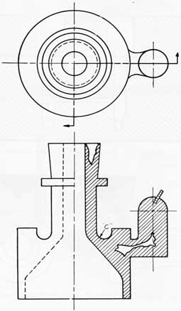
For a split pattern, such as that for a pump housing, a smooth ram-up board and a bottom board are needed. The ram-up board should be
65
of sufficient size to project an inch or two beyond the flask. A one-piece board, such as 3/4-inch plywood, is preferred. The use of such a ram-up board keeps mold finishing and slicking to a minimum.
Before use, the pattern should be checked for cleanliness and the free working of any loose pieces which must seat securely. Any chills which will be required should be clean and on hand ready for use. The chills should be checked to make sure that they fit the pattern correctly and have the proper means for anchoring them.
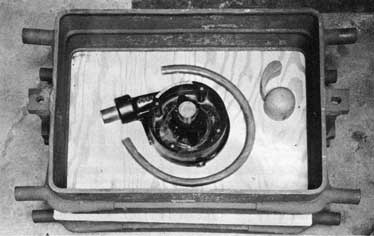
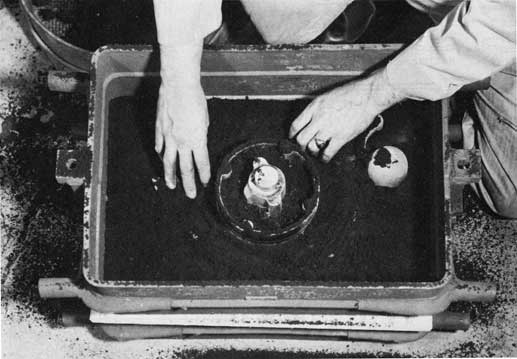
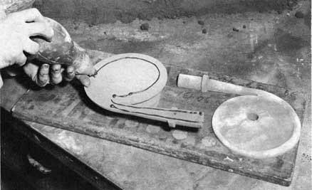
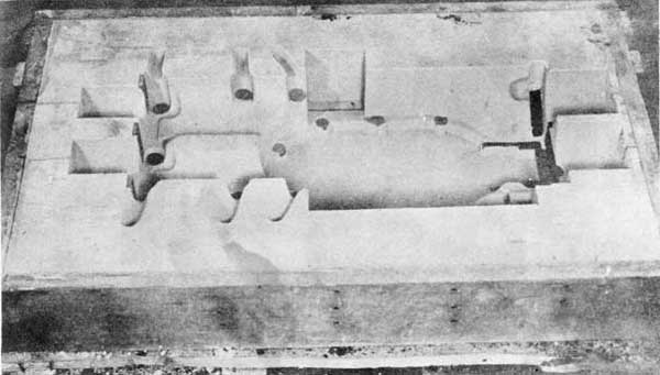
When using a split pattern, the drag part of the flask is turned upside down and placed on the ram-up board. If the flask is not too large, the ram-up board and drag can be placed on the cope of the flask. The drag pattern is placed with the parting surface down on the ram-up board along with any pieces used for the gating and risering system. Figure 78 shows a pump-housing pattern set in the drag with the parts of the gating system. The facing sand is then riddled to a depth of about one inch on the pattern and the ram-up board. Riddling of the sand is absolutely necessary for good reproduction of the pattern. The riddled sand is then tucked into all pockets and sharp corners and hand packed around the pattern as shown in figure 79.
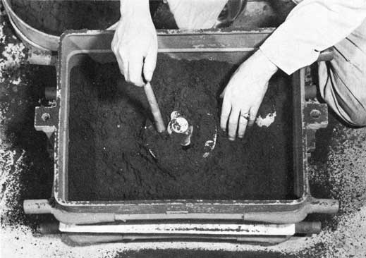
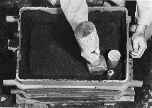
Backing sand is then put into the flask to cover the facing sand to a depth of three or four inches. The backing sand should be carefully rammed into any deep pockets as shown in figure 80. The remainder of the mold is then rammed with a pneumatic or hand rammer, care being taken to avoid hitting or coming too close to the pattern. The mold must be rammed uniformly hard in order to obtain a smooth, easily cleaned casting surface and to avoid metal penetration into the sand, swelling, break-outs, or other casting defects. When this ramming is completed, five or six more inches of sand are added at a time and rammed until the flask is filled to a point about one inch above the top of the flask.
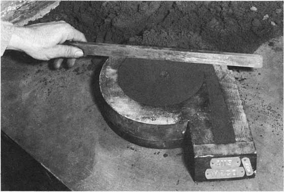
Next, the excess sand is "struck off," by means of a straight edge or strike as shown in figure 81. Instead of striking the sand in one motion, it is often easier to loosen the sand by a series of short strokes and then remove it with one motion. When the struck-off surface is smooth, a scattering of a small amount of loose sand on the struck surface helps to give better contact with the bottom board. The bottom board is placed into position with a slight circular motion. Good, full, and solid contact between bottom board and drag sand is important if the mold and pattern are to have adequate support when they are rolled over. The drag section is then clamped between the bottom
board and the ram-up board and turned over. The ram-up board (which is now on top) is removed and the mold face cleaned and slicked. Figure 82 shows the drag of the mold ready for the cope.
A parting material is sprinkled over the mold joint and pattern. The parting material prevents the sand in the cope from sticking to the sand in the drag when the cope is rammed up. The parting material for large castings is usually fine silica sand. For medium and small castings, finely ground powders (such as talc or silica flour) are used.
The cope of the flask is set on the drag and seated firmly with the aid of the flask pins. The cope pattern, riser forms, and any other parts of the gating system are set in their proper positions. Figure 83 shows the mold with the cope pattern, sprue, whirl-gate, and cross-gate pieces set.
The facing sand is riddled into the cope and hand packed around corners and in deep pockets. At this point, any gaggers which are necessary are placed. Care should be taken not to set the gaggers too close to the pattern risers or parts of the gating system. Gaggers set too close to the mold surface will cause undesired chilling of the metal. Any mold showing exposed gagger s in the cope after the cope pattern has been drawn, should be shaken out and made over. The number of gaggers and supporting bars will depend upon the size of the casting. Large flasks will require cope bars to support the sand. Gaggers may be fastened to the cope bars. The flask is then filled with sand and rammed as in making the drag. The sand should be packed by hand around any riser forms or raised portion of the pattern and care should be taken to avoid striking any forms or patterns during ramming. The partially filled cope is shown in figure 84. Notice that the cope has been peened around the inside edge of the flask. This procedure should be followed for both cope and drag, as it serves to pack the sand tightly against the flask and to prevent the sand from dropping out during handling. Also notice that the sprue and swirl gate form are slightly below the top of the cope of the flask. The cope is filled the same as the drag with successive fillings and uniform ramming. The completed mold is then struck off. With the riser, gating, and sprue forms a little below the top of the flask, the excess sand can be struck off without disturbing them.
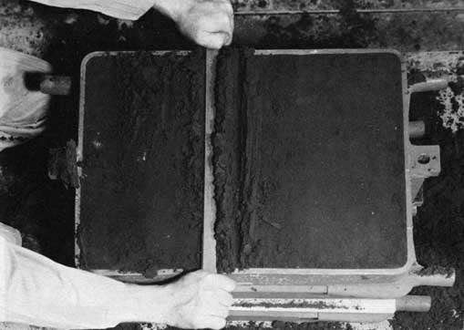
After the mold has been struck off, it is vented in the cope as shown in figure 85. The cope is then removed from the drag, set on its side, and rolled over to facilitate drawing the cope pattern. By tapping the runner, riser, and sprue forms lightly on the parting side of the cope, they will come free easily and can be removed.
66
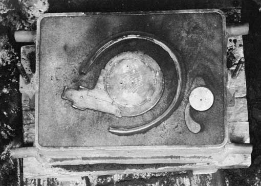
Any cope pattern pieces are also withdrawn at this time. The pieces used for the gating system are drawn from the drag. Cutting of in-gates is done before drawing the pattern if possible. Loose sand should be cleaned from the drag. The drag pattern is drawn by the use of eyebolts or draw pins as dictated by the pattern. A light rapping of the pattern and eye bolt before and at the beginning of the draw will make this operation easier. (NOTE: avoid excessive rapping.) The beginning of the pattern draw for the pump housing is shown in figure 86. The drawn pattern is shown in figure 87. Notice that this pattern was drawn with both hands. Such procedures give the molder better control over the pattern. The cope and drag are both inspected and cleaned, if necessary. Slicking of the mold should be kept to a minimum, but the pouring gate in the cope should be compacted and smoothed so as to eliminate loose sand and prevent washing out by the molten metal.
If any facing nails are required to resist washing of the mold face, they should be placed at this time. Any sharp corners or fins of sand in the mold cavity or in the gating system should be carefully removed. Any such projections will be washed out by the stream of molten metal and result in defective castings.
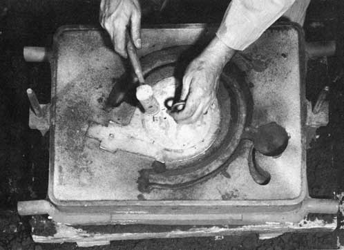
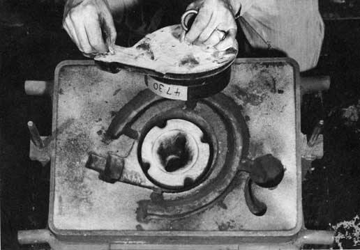
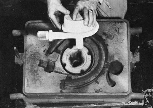
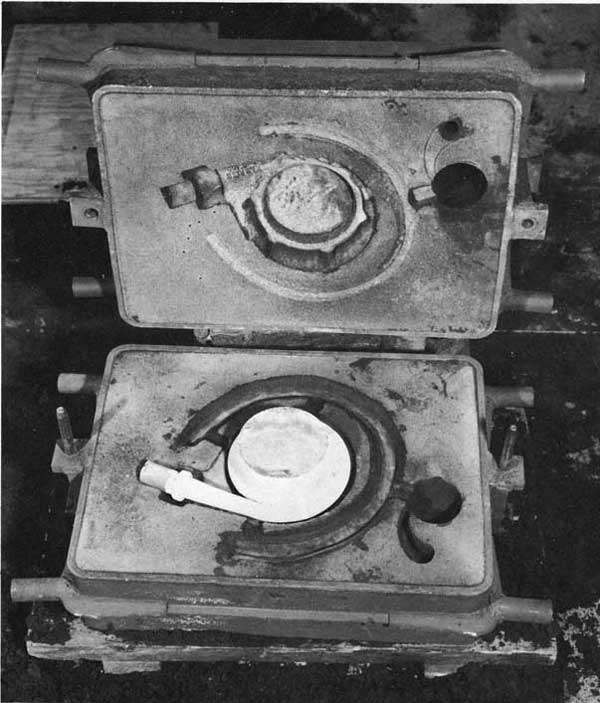
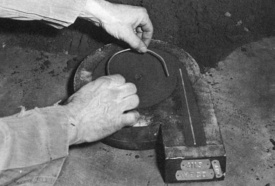
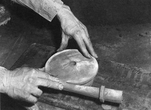
Once the cope and drag have been properly finished, the cores should be set in place. It is good practice to rest the arms against the body while setting the core to make the operation easier and smoother and to avoid damage to the mold. Both hands should be used for setting all but the smallest cores. The handling of the core for the pump housing is shown in figure 88. The cope and drag with the core set and ready for closing are shown in figure 89.
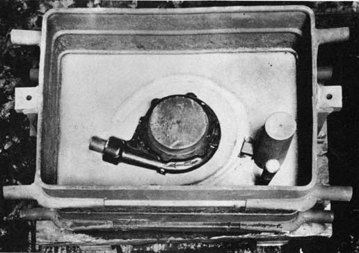
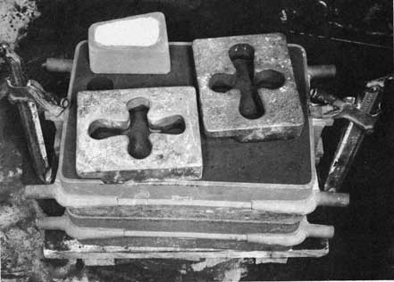
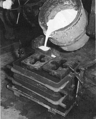
The mold is closed carefully by using pins to guide the cope. The cope should be lowered slowly and kept level. Any binding on the pins because of cocking of the cope should be avoided. A jerking motion caused by binding pins often causes sand to drop from the cope. This is one reason why flask equipment should be kept in top condition. After the mold is closed, it is clamped, the weights are placed, and the pouring cup or basin set over the sprue. The mold, ready for pouring, is shown in figure 90.
The proper pouring techniques are discussed in detail in Chapter 9, "Pouring Castings." Pouring of the pump housing is shown in figure 91. A block of iron was used to hold the pouring basin down. Notice that the lip of the ladle is close to the basin and that the basin is kept full of metal.
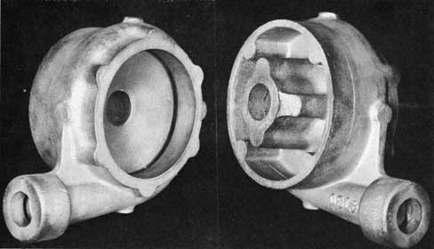
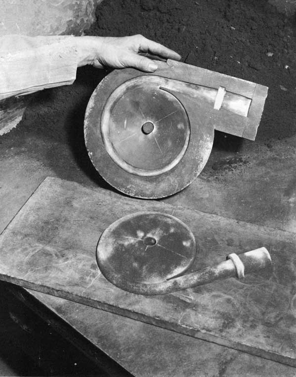
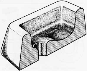
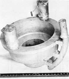
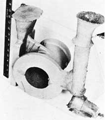
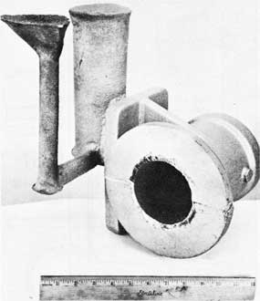
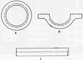
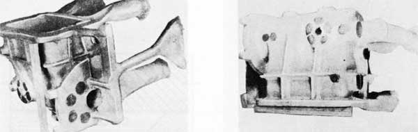
The finished pump-housing casting is shown in the two views in figure 92.
MOLDING MOUNTED PATTERNS
A mounted pattern is one which is attached to a ram-up board. It is called a match-plate pattern if the cope pattern is mounted on one side of the board and the drag pattern on the other. For a match-plate, the cope and drag patterns must be aligned perfectly.
The molding of a mounted pattern is much easier than the molding of loose patterns. Mounted patterns are usually metal and are used for quantity production, but their use is often justified when quite a few castings of one design are required. Mounted patterns may also be of wood, but these require proper care and storage facilities to prevent warping.
The advantages of a mounted pattern are that the parting-line surface can be rammed much harder than with loose-pattern molding and a vibrator can be attached to the pattern plate to make the drawing of the pattern much easier. Another important advantage is that the gating and risering system can be made a fixed part of the pattern. As a result, smooth hard surfaces will be obtained and sand-erosion problems reduced.
The sequence of operations for molding with mounted patterns is the same as for molding loose patterns. The pattern is set between the cope and drag parts of the flask and held in place by the flask pin. The drag is rammed up first, the flask rolled over, and the cope rammed up. When the mold is completed, the cope is drawn off the pattern and then the pattern drawn from the drag. Core-setting operations and closing the mold are the same as for loose pattern molding.
FALSE-COPE MOLDING AND THE USE OF BROKEN PARTS AS PATTERNS
Some patterns do not have a straight or flat parting line that permits them to be placed solidly against a ram-up board. Broken castings or parts which are to be used as a pattern usually fall into this class. Very often castings of this type would be impossible to mold by the common cope-and-drag method. The difficulties come from the facts that: (1) the parting line is not straight, and (2) the pattern or broken part requires special support while being molded. The false-cope method provides this extra support and makes it possible to have a very irregular parting line. Essentially the method consists of molding the part or pattern roughly into a false cope that is used to support the part while the final drag section is molded. The false cope is then removed and a final cope section molded Lo take its place in the final mold assembly.
67
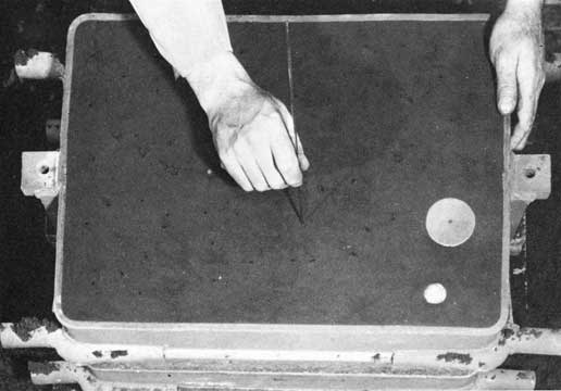
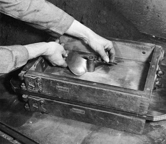
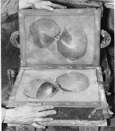
The cutting of an irregular parting line is probably the most important step in false-cope molding and will be described here. A small boat propeller is used as the pattern.
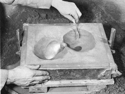
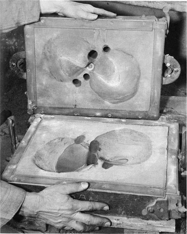
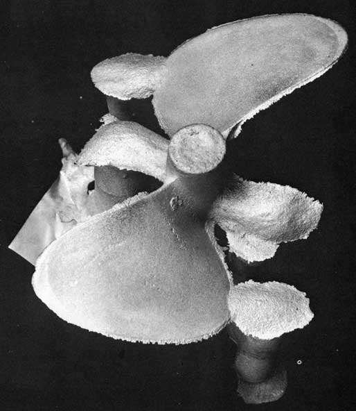
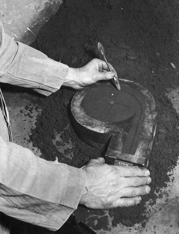
The propeller is set in the drag, on the ram-up board, as shown in figure 93. The facing sand is riddled onto the pattern, and the drag filled with sand and rammed in the conventional manner. The bottom board is set and the flask rolled over. The cope of the flask and ram-up board are removed. The parting line is then cut with the use of spoons and slicks. The sand must be removed to provide a gradual slope from the casting parting line to the flask parting line. A 45° slope usually is the maximum that can be tolerated and prevent sand from dropping. The completely cut parting line is shown in figure 94. The cope section of the flask is set in position, parting compound sprinkled on the drag, and the cope rammed. Extreme care must be taken in ramming to prevent damage to the drag. After the cope is completed, it is carefully removed from the drag. The drawn cope is shown with the drag in figure 95. The pattern is then drawn, and the sprue, gates, and risers cut. The mold ready for closing is shown in figure 96. The as-cast propeller is shown in figure 97.
In false-cope molding, the false cope provides a bearing surface for the pattern when ramming up the drag. It has the advantage that the finished mold is not disturbed in cutting the parting line.
The preparation of a false cope consists of molding the pattern in the cope and cutting the parting line. The sand is rammed as hard as possible to provide a good bearing surface when ramming the drag. An alternative way of preparing a false cope is to ram the cope without the pattern. The pattern is then bedded into the parting line side of the cope. The parting line can be cut into the cope or built up with additional sand, or it may be a combination of both.
The drag section of the flask is then placed into position, parting material sprinkled over the mold joint, and the drag made as described for loose-pattern molding. The flask is then rolled over and the cope drawn. Extreme care must be taken in drawing the cope. The original cope is discarded, the cope section returned to the drag, parting compound sprinkled over the mold joint and a new cope made. Extreme care must be taken in ramming the cope to prevent any damage to the drag. The cope is then carefully drawn, the pattern drawn, sprues, gates, and risers cut, and the mold closed. This type of molding provides a firm, sharp, parting line without any loose sand particles that might wash into the mold cavity.
If several castings are required from a pattern with an irregular parting line, a more permanent type of false cope, or "follow board" can be used. A shallow box, the size of the flask and deep enough for the cope section of the pattern, is made from wood. The box should be made so that it is held in place by the flask pins. The pattern should be given a light grease coating to prevent any sticking. It is then positioned in the box, cope side up, in the manner previously described. Plaster is poured around the pattern and permitted to set firmly but not hard. The false cope and follow board are then turned over together. The pattern is worked back and forth slightly so that it can be drawn easily. While the plaster is still workable, the parting line is cut and the plaster permitted to harden. After the plaster has dried completely, it may be coated with shellac to prevent any moisture pickup. Nails may be used through the sides of the frame to help support the plaster. A follow board may be made in a similar manner by building up the required backing with fireclay mixed to the consistency of heavy putty, and working it around the pattern. A fireclay match has the disadvantage that it must be kept slightly moist to keep the fireclay from cracking.
The follow board is used in place of the false cope in providing the necessary support when ramming the drag. The pattern is set in the follow board, and the drag rammed up as for molding a loose pattern. After the bottom board is set, the drag is rolled right side up and the match plate drawn, exposing the pattern in the drag with the parting line made. The cope is then placed and the molding completed as for loose -pattern molding.
SETTING CORES, CHILLS, AND CHAPLETS
In the setting of cores, it is important to check the size of the core print against the core itself. A core print is a depression or cavity in the cope or drag, or both. The print is used to support a core and, when the core is set, is completely filled by the supporting extensions on the core. A typical example of a core print in use is shown at the extreme left of the mold in figure 89. An oversize print or an undersize core will cause fins on the completed castings, which may lead to cracks or chilled sections in the core area. An oversize core or an undersize print may cause the mold to be crushed and result in loose sand in the mold and a dirty casting.
Setting simple cores in the drag should be no problem to a molder. Care should be taken in handling and setting the core. After a core has been properly set, it should be seated by pressing it lightly into the prints. Another item which should be checked is the venting of cores
452605 0-58-6
68
through the mold. Many times, the cores themselves are properly vented but the molder forgets to provide a vent through the mold for the core gases to escape.
In come instances, the cores may have to be tied to the cope. In such a case, they are attached to the cope by wires extending through the cope. The wires are wound around long rods resting on the top of the cope to provide additional support. The rods should rest on the flask to prevent crushing or cracking of the cope.
Such operations should be done with the cope resting on its side or face up. The tieing should be done with as little disturbance as possible to the rammed surface. The core should be drawn up tight to prevent any movement of the core while the mold is being closed. Before closing the mold, the cope should be checked to make sure it is free of any loose sand.
Chills are rammed in place with the mold and are described under "Molding Tools" in this chapter. Again it is emphasized that chills must be clean and dry. Even chills which have just been removed from a newly shaken-out mold should be checked before immediate reuse.
The use of chaplets was described earlier in this chapter under "Molding Tools." It must be remembered that chaplets should be used only when absolutely necessary. Preferably, another method for support (for example, core prints) should be used, if at all possible. The
use of chaplets in pressure castings should be completely avoided.
CLOSING MOLDS
The most important factor in the proper and easy closing of molds is to have flask equipment in good condition. Clean pins and bushings and straight sides on the flasks are the factors that make the closing of molds an easy operation. The opening of a mold after it has been closed is sometimes recommended. This procedure may prove useful. By using an excess of parting compound, the molder can then determine, with a fair degree of certainty, any mismatch or crushing of the mold. Nevertheless, the fewer times a mold is handled, the fewer chances there are to jar it and cause sand to drop.
SUMMARY
The molding operation aboard ship depends primarily on the molder and his ability to do his job. Skill in this type of molding can be attained only through experience, but a high level of skill can be reached in a shorter length of time by following correct molding techniques. For a beginning molder, it may appear much easier to patch molds that have been made haphazardly, than to take the time to make them properly. A molding technique based on careful attention to the various details involved in making a mold is by far the best approach to attaining molding skill. As with many other trades, speed in molding comes about by itself, if proper attention is given to the basic techniques.
Figure 76. Recommended chaplet design for emergency use.
Figure 77. Anchoring cores with chaplets.
Figure 78. Pattern set in drag with gating system parts.
72
Figure 79. Hand packing riddled sand around the pattern.
Figure 80. Ramming a deep pocket.
73
Figure 81. Striking off the drag.
Figure 82. Drag ready for the cope.
74
Figure 83. Cope with pattern and gating pieces set.
Figure 84. Ramming the partially filled cope.
75
Figure 85. Venting the cope.
Figure 86. Start of the pattern draw.
76
Figure 87. Pattern completely drawn.
Figure 88. Setting the core.
77
Figure 89. Cope and drag ready for closing.
78
Figure 90. Clamped mold with weights and pouring basin.
Figure 91. Pouring the mold.
79
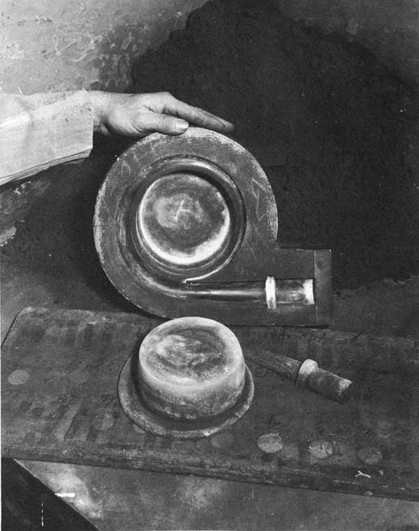
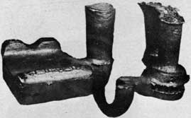
Figure 92. Finished pump housing casting.
Figure 93. Propeller set in the drag.
80
Figure 94. Propeller in the drag with parting line cut.
Figure 95. Drawn cope.
81
Figure 96. Mold ready for closing.
82
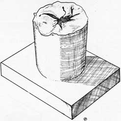
Figure 97. As-cast propeller.
83
Chapter VI MAKING CORES
Cores are used for forming internal cavities in a casting, for forming parts of molds when the pattern is difficult to draw, or for details that are difficult to make in molding sand. The various properties required of good cores are discussed in detail in Chapter 4, "Sands for Molds and Cores." Briefly, the properties desired in a core are: (1) refractoriness, (2) some green strength, (3) high dry strength, (4) good collapsibility, (5) a minimum amount of gas generation by the core during casting, (6) good permeability, and (7) high density.
CORE MAKING TOOLS AND ACCESSORIES
Tools and accessories used in the making of cores are the same as those used for making molds, with the addition of coreboxes, sweeps, core driers, and special venting rods. Cores are shaped by the use of the core boxes, by the use of sweeps, or by a combination of these methods. Sweeps are limited in their use and will not be discussed here. Core driers are special racks used to support complicated cores during baking. They are usually not used unless a large number of cores of a particular design are being made. Complicated cores can often be made as split cores, baked on flat drying plates, and then assembled by pasting.
TYPES OF CORES
BAKED SAND CORES
Core work aboard ship is concerned primarily with baked sand cores. They have the desired properties, are easy to handle, and may be made up ahead of time and stored in a dry place for future use. Baked sand cores have higher strengths than dry-sand cores. This means that complicated cores can be made most easily as baked cores.
DRY-SAND CORES
Dry-sand cores are made from green-sand mixtures to which additional amounts of binders have been added. They are dried in the air or with a torch and their strength comes from the large amount of binder. Dry-sand cores are not as strong as baked sand cores and require more internal support and careful handling. Although they can be made faster than baked sand cores, this is often offset by disadvantages of lower strength and the need for more careful handling.
452605 0-58-7
INTERNAL SUPPORT
Cores are made from sand mixtures that are very weak before they are baked or dried. These mixtures often need some reinforcing. Large or complicated cores need proper arbors or reinforcing rods in the sand to permit handling of the unbaked core and to help support the baked core in the mold. When a core is made entirely of sand, the force tending to lift it is quite great when metal is poured around it, but when the core is hollowed out or filled with coke or cinders, as is often done to improve collapsibility, the force is even greater. If a core shifts, floats, deforms, or breaks, the casting is almost always defective.
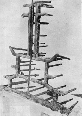
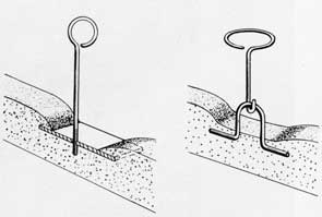
Figure 98 shows a cast iron arbor used to support a core of medium size. Figure 99 shows the core rammed with the arbor in place. Arbors can also be made by tying rods or wires together, or by welding rods or strips together. Cast iron arbors are seldom used for small work; steel rods or wires are more commonly used. When placing rods or arbors, support them to avoid all twisting, bending, or breaking forces. Place the support in such a way that it does not interfere with the proper hollowing or "gutting out" of the core. Hollowing is done to improve collapsibility after the casting is poured. Care should be taken to make certain that the arbor or rod does not project through the surface of the core or even approach too close to it. All pockets or projecting parts of the core should be made with rods to make it easier to draw the core box and to give good support for the core. Figure 100 shows a typical method for supporting cores which must be suspended from the cope. Figure 101 shows lifting-hook assemblies used for handling and fastening large cores.
FACING, RAMMING, RELIEF, AND VENTING OF CORES
After obtaining the core box and selecting the proper reinforcing rods or arbor, the next operation is to put the core sand uniformly into the core box to a depth of approximately 1/2 inch or more, depending on the size of core and thickness of the casting. The sand should be free flowing and should not require hard ramming, but it is necessary that it be rammed sufficiently to develop a smooth, uniform surface. In pockets, tucking the sand in place with the fingers or suitable tools is necessary. Many core makers tend to overlook the importance of this operation and its omission is a source
84
of continual trouble. Uniformity of ramming is a big factor affecting green and dry strength, ease of cleaning, and the quality of the casting surface.
After or during the ramming of the facing material, the reinforcements are placed. For small cores, the entire box may be filled with facing sand prior to placing the rods. In making medium and large cores, the facing material may be backed up with old molding sand, cinders or coke to support the core. This material, after drying, can easily be removed to provide space for venting and for collapsibility of the core.
One of the necessary requirements of a core is venting. In some of the simple cores, venting is easy, but in the more intricate ones, it is often difficult. A small, round core may be vented by running a vent rod through its center after ramming. A core made in halves may be vented by cutting channels through the body and core prints at the parting line before baking. When neither of these methods can be applied, a wax vent should be used. It is buried in the sand along the line or lines that the escaping gas is to follow. When the core is baked, the wax melts and disappears into the body of the core, leaving the desired vent channels. Care should be taken to avoid using too much wax, as it produces gas when heated by the molten metal. Cores made with coke cinders, gravel, or similar material in their central sections do not usually need additional venting.
The importance of good ramming, a uniformly smooth surface on a core, and of proper venting cannot be emphasized too strongly. When cores have a tendency to sag before baking or during baking, they can often be supported in a bed of loose green sand which can be brushed off the core after it is baked.
TURNING OUT AND SPRAYING
After the core box is filled and the excess sand is removed, a metal plate is placed on the box, the whole is turned over, and the box is rapped or vibrated as it is drawn away from the sand. There are several precautions to be observed in this operation. The core plate should be clean and straight and should be perforated to facilitate drying of the core. Care should be taken to avoid hard rapping of the box. This causes distorted cores.
After the core is freed from the box, all fins and irregularities must be removed. The core should be sprayed or painted with the proper wash as described in Chapter 4, "Sands for Molds and Cores."
A silica wash or spray is a good general-purpose material to smooth the surface of the core to give a smoother casting. With a little practice, washes can be applied to a core either before or after it is baked. The wash should be heavy enough to fill the openings between the sand grains at the surface of the core, but not so heavy that it will crack or flake off when it is dried.
BAKING
In the baking of oil sand cores, two things occur. First, the moisture is driven off. Following this, the temperature rises, causing drying and partial oxidation of the oil. In this way, the strength of the core is developed.
For proper baking of oil sand cores, a uniform temperature is needed. This temperature should be not over 500°F., nor under 375°F. If linseed oil cores are baked at a moderate temperature of 375°F. or 400°F., they will be quite strong. The same cores baked quickly at 500°F. will be mush weaker. Baking the cores to the point where the bonding material decomposes must be avoided, or the cores will lose strength.
The size of the core must be considered in drying. The outer surface of a core will bake fast and will be the first part to develop maximum strength. If the temperature is maintained, the inside will continue to bake until it finally reaches maximum strength, but by that time the outer surface may be overbaked and low in strength. The tendency for this to happen in large cores can be partly overcome by filling the center of the core with highly porous material with a low moisture and bond content (for example, cinders or coke), by the use of well-perforated plates, and by using low baking temperatures. It is not only a matter of heating the center of the core but also of supplying it with oxygen. Thus, there is need for free circulation of air around and through the core while baking.
The most skillful and careful preparation of metal and mold can easily be canceled by poor cores. The need for proper baking cannot be overemphasized. If cores are not properly baked, the following is likely to happen to the casting:
1. Excessive stress, possible cracks, caused when the core continues to bake from the heat of the metal, thus increasing the strength of the core at the time the metal is freezing and contracting.
2. Unsoundness from core gases not baked out.
85
3. Entrapped dirt from eroded or spalled sand from weak cores.
When overbaked, the loss of strength of the core results in excessive breakage in handling or during casting, and cutting or eroding of the core surface.
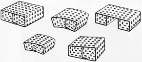
To establish a full appreciation of the problems of drying cores, a series of 3, 5, and 8-inch cube cores should be made without rods and then baked at temperatures of 400°F., 425°F., 450°F., 475°F., and 500°F. for varying times. After being taken out of the oven and cooled, they should be cut open with a saw to determine the extent to which they are baked. Conducting this simple test will aid in determining the proper time and temperatures to use for various cores in a given oven.
Practice is necessary to accurately determine when a core is baked properly. A practical method is to observe the color of the core. When it has turned a uniform nut brown, it is usually properly baked. A lighter color indicates insufficient baking and a darker color indicates overbaking.
Mechanical venting of the core by using many vent holes and then carrying these to the prints on the core joint will facilitate baking.
CLEANING AND ASSEMBLY
At the baking temperature, cores are quite fragile. Thus, after being removed from the oven, they should be allowed to cool to below 125°F. before being taken from the core plates.
When cool, all excess materials such as fine and loose sand should be cleaned from them. Sand, gravel, or cinders used for fill-in material should be removed to provide for the collapsibility of the core and to improve venting.
Vents should be cut in such a way as to prevent metal from entering them when the casting is poured. Make sure at all times that vents are adequate to permit the full flow of core gases as they are generated. Overventing does no harm. Underventing gives bad castings.
After this, the core should be fitted together with a gage for control of size. The use of gages for assembling cores is necessary for producing quality castings.
When properly cleaned and gaged, the core sections are then assembled using a plate mixed as follows:
3 % bentonite
6 % dextrine
91 % silica flour (200 mesh or finer)
Water to develop the correct pasty consistency.
After this, all joints are sealed with a filler mixed as follows:
3 % bentonite
3 % dextrine
94 % silica flour (200 mesh or finer)
Water to develop the consistency of a thin putty.
The filler and paste are dried by returning the core to an oven for a short period or by local application of heat (as from a torch).
The above paste and filler developed at the Naval Research Laboratory have been found to give excellent results. A major caution to be observed in their use is to see that they are thoroughly mixed in the dry state before adding water, and again thoroughly mixed after the water is added.
STORAGE OF CORES
Storage time has an important effect on the quality of cores and upon the resulting castings. Baked or dry cores decrease in strength because they pickup moisture from the air, particularly on the surface. For this reason, it is unwise to make cores much in advance of requirements, usually not over 24 hours. If baked or dry cores must be stored, put them in a dry place.
Consideration must also be given to the storage of cores prior to baking. If cores are allowed to stand for too long a time before baking, evaporation of the surface moisture may take place and give a weak surface on the core. For thin cores of a large surface area, 10 minutes may be too much time for standing out of the oven, while for heavier cores more time may be allowed. In all cases, the time should be kept at a minimum.
MAKING A PUMP-HOUSING CORE
The following figures show the various steps in making the core for the pump-housing casting shown in Chapter 5, "Making Molds:"
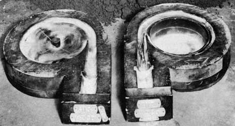
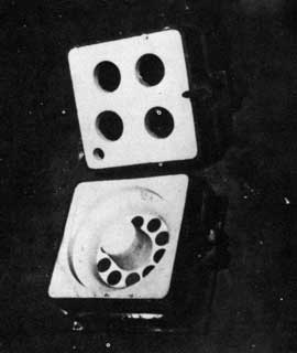
The two core boxes for making the parts for the pump-housing core are shown in figure 102. A parting compound has been sprinkled on the core boxes to make it easier to turn out the core. Ramming of the sand in one of the core boxes is shown in figure 103 and striking off of the core is shown in figure 104. Placing
86
of the reinforcing rods is shown in figure 105. Additional sand is then added, the core rammed lightly again and struck off. The reinforcing rods can also be placed when the core is partially rammed. Cutting the vents with a molding tool is shown in figure 106. Notice that one vent comes out the end of the core, while other vents radiate from the center and vent through the center of the supporting core. The idea is to give gases inside the core a free passageway out of the core. The two core halves are shown in figures 107 and 108 after they have been turned out of the core boxes. After the two core halves are baked, core paste is applied with a small rubber squeeze bulb, as shown in figure 109. Note that there is no excess of core paste. Core paste on the outside of a core can cause a defective casting because of gas formation. The assembling of the two core halves is shown in figure 110. The assembled core must then be baked for a short time to dry the paste. The completed core after it is sprayed is shown in figure 88, Chapter 5, "Making Molds."
SUMMARY
Cores should always be made with accurate, clean equipment and should have the following qualities to a degree suitable for the purpose intended:
1. Refractoriness to withstand the casting heat. This is obtained by selection of material and proper processing.
2. Strength to withstand handling and casting forces. This is obtained by the use of the proper amount of binders and by good internal structural supports.
3. Collapsibility to permit breakdown during contraction of the casting and ease of cleaning. By avoiding the use of sands bonded too strongly and by hollowing out the center or filling it with coke, cinders, gravel, or weak sand, this quality may be obtained.
4. Smooth strong surface to provide a good casting finish, internal cleanliness, and ease of cleaning. This quality is obtained by the use of an adequately bonded refractory sand, uniformly hard rammed, baked immediately after being made, and used shortly after baking.
5. Low gas content to prevent unsoundness in the casting. This quality is obtained by using the minimum of organic binding materials, baking well, and venting thoroughly. All of the above features are essential in core making and are regularly obtained only by good core
practice.
87
Figure 98. Arbor for a medium-size core.
Figure 99. View of inside of core showing hollowing to make the core more collapsible when metal is poured around it.
Figure 100. Section of mold showing use of lifting eye for supporting heavy core.
Figure 101. Typical lifting hooks for lifting cores.
88
Figure 102. Core boxes for pump housing core.
Figure 103. Ramming up the core.
89
Figure 104. Striking off the core.
Figure 105. Placing the reinforcing rods.
90
Figure 106. Cutting vents.
91
Figure 107. Drag core turned out.
92
Figure 108. Cope core turned out.
93
Figure 109. Applying core paste.
Figure 110. Assembling the two core halves.
94
This page is blank.
95
Chapter VII GATES, RISERS AND CHILLS
GENERAL PURPOSE
Gates, risers, and chills are closely related. The function of one cannot be explained without reference to the others. This interrelationship is also carried into the casting itself. The best gating practice can be nullified by poor risering practice, and improper use of chills can cause the scrapping of well-gated and properly risered castings. The purpose of the gating system is to deliver the molten metal to the mold. The risers are used to supply liquid metal to compensate for solidification shrinkage in heavy sections; that is, they "feed" the casting. Chills are used to set up temperature gradients in a casting and permit full use to be made of directional solidification. They make one part of a casting solidify ahead of another. The proper use of gates, risers, and chills are important tools of the foundryman in producing a good casting.
GATING SYSTEM
A gating system should be able to do the following:
1. Permit complete filling of the mold cavity.
2. Introduce the molten metal into the mold with as little turbulence as possible so as to minimize gas pickup and prevent damage to the mold.
3. Regulate the rate at which the molten metal enters the mold cavity.
4. Establish the best possible temperature gradients within the casting so that directional solidification can be fully utilized, and prevent casting defects due to poor thermal gradients.
To achieve these aims, steps must be taken to control the following:
1. The type of ladle and ladle equipment.
2. The size, type, and location of sprue and runner.
3. The size, number, and location of gates entering the mold cavity.
4. The rate of pouring.
5. The position of the mold during casting.
6. The temperature and fluidity of the metal.
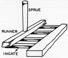
The various parts of a simple gating system are shown in figure 111.
GENERAL RULES OF GATING
The following general rules are given as a guide in making good gating systems:
1. Use Round Sprues. (a) Round gates or the closest approach to round gates are preferred. (b) A circular cross section has the minimum surface exposed for cooling and offers the lowest resistance to flow.
2. Taper the Sprue. The sprue should be tapered with the smaller end toward the casting. This makes is possible to keep the down-gate full of metal when pouring. Never locate a tapered sprue so that metal is poured into the smaller end.
3. Streamline the Gating System. Gating systems having sudden changes in direction cause slower filling of the mold cavity, are easily eroded, and cause turbulence in the liquid metal with resulting gas pickup. Streamlining of the gating system eliminates or minimizes these problems. Avoid right-angle turns.
(a) Round sprues are preferred for sprue diameters of 3/4 inch or less. Larger sprues should be square or rectangular. However, a 3/4 inch diameter sprue is about the maximum size that can be kept full of metal while hand pouring.
(b) Wide flat gates and runners are preferred for light metal alloys.
4. Use Patterns for the Gates. The gating system should be formed as part of the pattern whenever possible. In the case of many loose patterns used aboard repair ships, gating patterns should be used instead of cutting the gates by hand. The use of patterns for the gates permits the sand to be rammed harder and reduces sand erosion or washing. Hand-cut gates expose loosened sand which is easily eroded by the flowing metal.
5. Maintain Proper Gating Ratio. There is a definite relationship between the cross-sectional areas of the sprue, runners, and in-gates, to produce the best filling conditions for the mold. The rate of filling the mold should not exceed the ability of the sprue to keep the entire gating system full of liquid metal at all times. The cross section of the runner should be reduced in size as each gate is passed. An
96
example of such a gating system is shown in figure 112. This keeps the runner full throughout its entire length and promotes uniform flow through all of the gates. If this procedure is not followed in a multiple-ingate system, all of the metal will have a tendency to flow through the ingates farthest from the sprue.
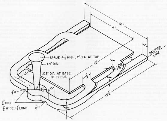
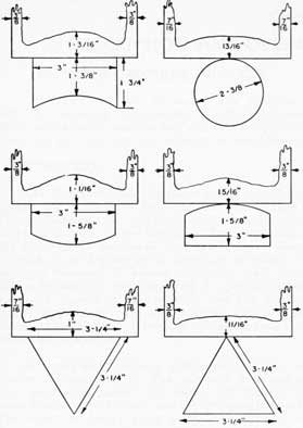
An example of the use of gating ratio can be made with figure 112. Aluminum was used to make this flat plate casting, and one of the gating ratios that has proven successful for this type of casting is a 1:3:3 ratio. The first number refers to the cross-sectional area of the sprue base, the second number refers to the total cross section of all the runners from that sprue, and the third number refers to the total cross-sectional area of the ingates. In other words, the area of the sprue base is 1/3 that of the total area of the runners, and the total cross-sectional area of the runners equals the total cross-sectional area of the ingates.
The size of the ingate for this plate casting was selected to be 1/4 inch thick and 1-1/2 inches wide. The individual ingate then has an area of 3/8 square inch. There are four ingates, so the total ingate area is 4 x 3/8 square inch, or 1.5 square inches. The total runner area is then also 1.5 square inches, as determined by the gating ratio. Since there are two runners, each runner must have a cross-sectional area of 0.75 square inches. In figure 112, this is shown by the runner dimensions of 3/4 inch thick by 1 inch wide. To complete the gating system, the sprue base must have a cross-sectional area equal to 1/3 that of the runners. This is equal to 1/2 square inch. A sprue with a base diameter of 4/5 inch will satisfy this requirement.
6. Maintain Small Ingate Contact. The area of contact between the ingate and the casting should be kept as small as possible (unless gating through side risers as described later),
7. Utilize Natural Channels. Ingates should be located so that the incoming flow of metal takes place along natural channels in the mold and does not strike directly on mold surfaces or cores. The continuous flow of metal against a mold or core surface quickly burns out the binder and washes the loose sand into the casting.
8. Use Multiple Ingates. Unless a casting is small and of simple design, several ingates should be used to distribute the metal to the mold, fill it more rapidly, and reduce the danger of hot spots.
9. Avoid Excessive Ingate Choke. The in-gate should not be choked at the mold so that it causes the metal to enter the mold at such a high speed that a shower effect is produced. Besides
excessive turbulence and oxidation of the metal, the mold may not be able to withstand this eroding force. Choking of the ingate to assist in gate removal is a proper procedure if a number of ingates are used to allow an adequate amount of metal to enter the mold without jet action.
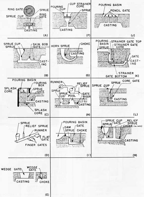
The recommended nomenclature for various types of gating is shown in figure 113. Additional information on gating systems for light metals is given in Chapter 15, "Aluminum-Base Alloys."
TYPES OF GATES
There are three general classifications for gates which are commonly used. They are: (1) bottom gates, (2) top gates, and (3) parting gates.
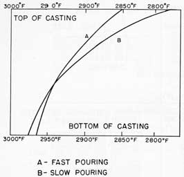
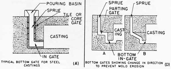
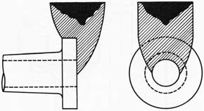
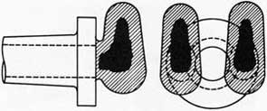
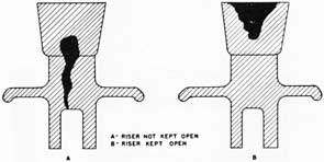
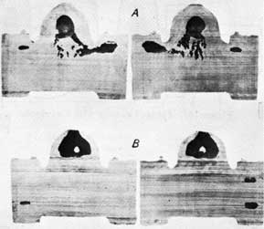
Bottom Gates. Bottom gates are most generally used because they keep mold and core erosion to a minimum. In spite of this, they have the very decided disadvantage of causing unfavorable temperature gradients in the casting, which make proper feeding particularly difficult and often impossible. Figure 114 shows the undesirable temperature gradients present in the bottom-gate and top-risered casting of figure 115, the latter showing the types of defect obtained with this method.
When using bottom gates, as the metal rises in the mold, it heats the mold with which it comes in contact. This produces relatively cold metal in the riser with considerably hotter metal next to the gate. In other words, there is hot metal and hot mold near the gate and cold metal in a cold mold near the riser. Such conditions are opposite to those desired for directional solidification in a casting. The risers should contain the hottest metal in the hottest part of the mold, and the coldest mold parts should be at points farthest removed from the risers.
Thus, bottom gating produces an unfavorable temperature gradient in the metal, the top of the casting is the coolest and the bottom is the hottest at the time the mold is filled. The amount of this temperature difference is related to the pouring rate, the rate of rise of the metal in the mold, and to the heat conductivity of the mold. A slow pouring rate will produce a temperature gradient more unfavorable than a fast pouring rate. When pouring slowly through a bottom gate, the metal has a greater opportunity to give up its heat to the lower portions of the mold than it would have if the mold were filled rapidly. The difference in temperature gradients due to slow and fast pouring is also shown in figure 114.
97
Unfavorable temperature gradients resulting from bottom gating are corrected to a slight extent by pouring through the riser as soon as the metal level becomes high enough. It is very difficult to perform this operation correctly.
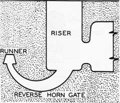
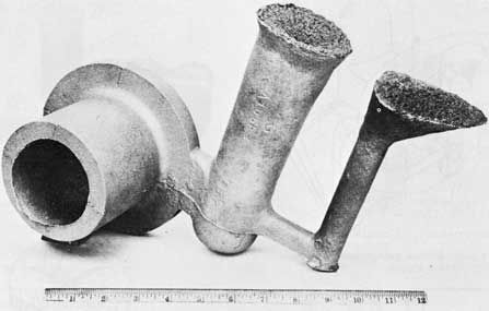
Two types of bottom gates are shown in figure 116. The horn gate is also a bottom gate, but has the disadvantage of producing a fountain effect within the mold, causing mold erosion and entrapping air. In general, horn gates should not be used unless they are of the reverse type, as shown in figure 117. This type of horn gate has the large end of the horn at the mold cavity, as shown in figure 118. When using a horn gate, it is best to gate into a riser, as shown in figures 117 and 120, rather than directly into the casting.
Besides allowing easy flow of the metal into the mold, thereby reducing the erosion of the mold and core surfaces by the molten metal, bottom gating also results in quiet, smooth flow, thus reducing the danger of entrapped air.
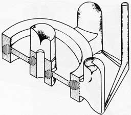
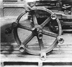
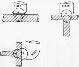
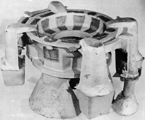
The advantages of bottom gating without its disadvantages can be obtained if the casting is gated through a side riser as shown in figure 119. This type of gating produces the best conditions for directional solidification with a minimum of turbulence in the metal. In figure 119, it will be noticed that the wheel casting is gated through two side risers to permit a rapid pouring and filling of the mold. The molten metal will flow by two paths and meet approximately equally distant from the two risers. This will permit directional solidification to take place toward the hot risers. The riser at the hub of the wheel is necessary to feed the heavy section at the hub.
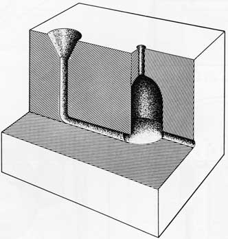
The bottom gate is often constructed with a well as part of the gating system, as in figure 121. The well acts as a cushion for the metal dropping down the sprue and prevents the erosion of sand, which is particularly apt to occur at the point of sudden change in the direction of flow. A special core (known as a splash core) may be used at the base of the sprue to minimize erosion of the sand.
Top Gates. Top gating of a casting is limited by the ability of the mold to withstand erosion, because the molten metal is usually poured through an open-top riser, such as shown in figure 122. Contrary to the characteristics of bottom gating, top gating has the advantage of producing favorable temperature gradients, but the disadvantage of excessive mold erosion. This method of gating is usually used for castings of simple design which are poured in gray iron. Top gating is not used with nonferrous alloys which form large amounts of dross when agitated.
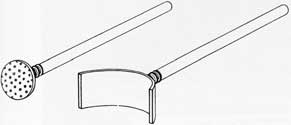
For some heavy metal castings, the metal will be poured through a shower or pencil gate, as shown in figure 123. Pencil gates permit the metal to fall in a number of small streams and help to reduce erosion of the mold.
Parting Gates. Parting-line gates are used most frequently because they are the easiest for the molder to construct, particularly in jobbing work. In addition, it is usually possible to gate directly into a riser.
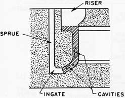
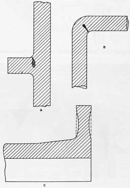
The main disadvantage of parting gates is that the molten metal drops in the mold to fill the drag part of the casting. Such a drop often causes erosion or washing of the mold. In nonferrous metals, dross formation is aggravated and air is often trapped to produce inferior castings. A typical parting gate is shown in figure 124. In this gating system, the sprue was used as a riser. A shrinkage defect formed in the indicated area because of improper feeding.
Gating through side risers should be used wherever possible. If this procedure is not used, hot spots will cause shrinkage defects. Gating directly into the casting produces hot spots, because all of the metal enters the casting through the gates and the sand near the gates becomes very hot and retards cooling of the metal. Unless risers are provided for feeding these portions of the casting with molten metal, cavities or shrinkage defects will be formed. Figure 125 shows gating into the riser with a parting gate.
Whirl gates, such as shown in figure 126, are sometimes used with heavy metals and parting gates. The purpose of these gates is to collect dross, slag, eroded sand, and to trap it, allowing only clean metal to enter the casting.
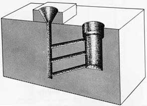
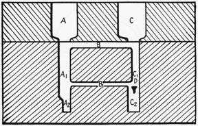
Step Gating. There is a fourth type of gating which is sometimes used. It is described here for information purposes only and its use is not recommended. The theory behind the step gate is that as the metal rises in the mold, each gate will feed the casting in succession. This would then put the hot metal in the riser where it is desired. Recent studies have shown that step gates do not work this way. To get proper step-gate feeding, a complicated step-gating design must be used. The use of step gates for castings normally made aboard repair ships is not recommended. A simple step gate is shown in figure 127.
USEFUL PROCEDURES
There are two ways in which the advantages of bottom gating can be obtained without serious disadvantages. They are: (1) mold manipulation, and (2) gating into blind risers.
98
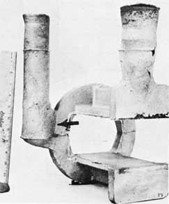
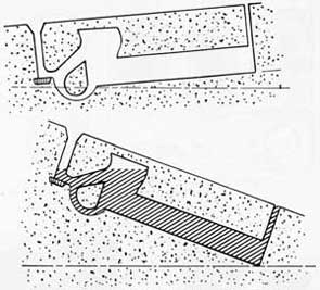
Mold Manipulation. Mold manipulation makes it possible to keep mold erosion to a minimum during pouring, and by altering the position of the mold, to obtain temperature gradients even more favorable than those obtained by top pouring. The mold is tilted with the ingate end lowest. After pouring is finished, the mold is turned through an angle of 30°, 100°, or 180°, depending on the design of the part. For mechanical reasons, 100° and 180° manipulations are limited to small and medium castings of suitable design, but 30° manipulations are common for both large and small castings. A 30° partial reversal for a bottom-gated casting is shown in figure 128.
The gating system shown in figure 128 was devised to insure the flow of metal through the bottom ingate (horn gate until the metal reached the bottom of the riser. After this, the balance of the mold is automatically filled through the upper gate and riser. This insures heating of the riser cavity and the proper conditions of hot metal and hot mold at the riser and cold mold and cold metal at the farthest point from the riser. This type of gate has the disadvantage that it is more difficult to mold and requires the use of a core. A pouring angle of 10° or 15° is found satisfactory for proper bottom gating. This enables the molten metal to travel forward as an unbroken stream, instead of fanning out over the entire mold cavity. This mold is then reversed through 30° to 40° after pouring to produce better feeding from the riser.
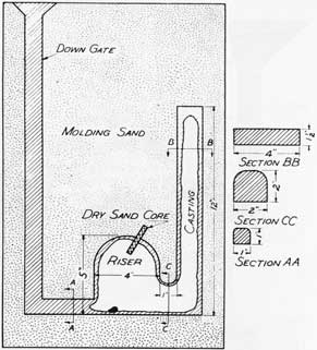
Total Reversal. The most favorable temperature gradient in both metal and mold may be obtained by the "total reversal" method as shown in figure 129. In this case, the feed head is molded on the bottom, with only small vents on the top of the mold, and the sprue enters the riser at the lowest point to prevent draining after reversal. After the casting is poured, the vents and the sprue are immediately sealed with wet sand and the mold reversed through an angle of 180° to bring the risers directly above the casting. The 180° reversal is used in the casting of what are commonly called "billets." There may be sufficient demand aboard ship for billets for the machine shop to warrant making a special rig to assist in reversing the mold.
Gating Into Blind Risers. By gating into blind risers attached to the lowest part of the casting, it is possible to take advantage of the bottom-gating system and not suffer from the formation of shrinkage cavities. In order to make a blind riser function well in such cases, it is best to have the gate enter directly into it. The proper use of blind risers is discussed later in this chapter.
POURING CUPS AND BASINS
Pouring cups make it easier to pour the molds. There are a few general principles
which must be considered when designing a pouring cup. The inside diameter of the cup at the top should be about 2.5 to 3 times that of the sprue diameter. The inside walls should be at a steep angle, so that the cup is easy to make. Cups for small sprues usually require shoulders as shown in figure 130, so that the cup will have sufficient depth. The hole in the bottom of the cup should exactly match the top of the sprue.
When designing a pouring cup, it should not be too small or it will be impossible to pour metal into it fast enough at the start to completely fill the sprue in time to prevent dirt or slag from flowing down the sprue. A shallow cup is difficult to fill without splashing and is more difficult to keep filled during pouring.
Pouring cups can be made out of backing sand with extra bonding material added so the cups will bake hard in an oven. The inside surface of the cup should be coated with silica wash to make it more resistant to erosion.
In the pouring of steel, it is necessary to use larger sprues and larger pouring cups than for cast iron, bronze, or aluminum. These latter metals are much more fluid than steel. The cups shown in figure 130 are adequate for steel and may be reduced in size for the other metals.
Performed pouring cups are much better than a simple depression scooped out of the top of the cope at the sprue. The disadvantage of a hand-cut pouring aid is that the sand is loosened and sharp corners are present so that sand is readily eroded by the flowing metal and carried into the casting. A pouring cup should be used whenever possible.
A pouring basin serves two additional purposes as compared with a pouring cup. It not only makes it easier to pour the mold, but it also regulates the flow of metal into the mold and aids in trapping and separating slag and dross from the metal before it enters the sprue. A simple pouring basin is shown in figure 131. To make a pouring basin work properly, a plug should be used with it. The plug can be made from core sand or a graphite rod. It should be long enough to extend well above the pouring basin. It is good practice to have a wire or thin metal rod fastened to the plug to make it easier to pull the plug from the basin. Refer to Chapter 9, "Pouring Castings," for the proper use of a pouring basin.
RISERS
The principal reason for using risers is to furnish liquid metal to compensate for solidification shrinkage in the casting. In addition to
99
this main function, a riser has other reasons for its use. It eliminates the hydraulic-ram effect (similar to water "pound" when a valve is closed suddenly), shown when the mold is full, flows off cold metal, and vents the mold.
Just at the time that a mold is completely filled with metal, there can be a sudden and large increase in pressure in the mold because of the motion of the flowing metal. This added pressure may be enough to cause a run-out of the casting or may produce a deformed casting. A riser permits the metal to flow continuously into it instead of coming to a sudden stop. This reduces the pressure or hydraulic-ram effect which produces these defects. An open riser permits the man pouring the mold to see how rapidly the mold is filling and provides him with a means to regulate the flow of metal.
When a casting must be poured rapidly, the permeability of the sand is not capable of permitting air and gases to escape quickly enough. In such a case, a riser provides an easy exit for the gases.
GENERAL RULES OF RISERING
The most important function of a riser is that of a reservoir of heat and molten metal. To be effective, it must be the last portion of the casting to solidify. There are four primary requirements which a satisfactory riser should meet:
1. The volume of the riser should be large enough to compensate for the metal contraction within the area of the casting it is designed to feed.
2. Enough fluid metal must be in the riser to penetrate to the last cavity within its feeding area.
3. The contact area of the riser with the casting must fully cover the area to be fed, or be designed so that all the needed feed metal in the riser will pass into the casting. See figure 143.
4. The riser should be effective in establishing a pronounced temperature gradient within the casting, so that the casting will solidify directionally toward the riser.
Accordingly, the shape, size, and location of the riser must be effectively controlled.
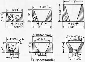
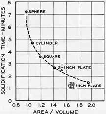
Riser Shape. The rate of solidification of a metal varies directly with the ratio of surface area to volume. In other words, for a given weight of metal, the shape which has the smallest surface area will take the longest time to solidify. The ratio of surface area to volume is obtained by dividing the surface area by the volume. In table 20 are listed some of the solidification times for various shapes of steel castings having the same weight.
TABLE 20. COMPARATIVE TIME FOR SOLIDIFICATION OF VARIOUS STEEL SHAPES
Form and Size of Riser
Volume, cu inch
Weight, lb
Area, sq inch
Amount Solidified in 1 Minute, lb/cu inch
Time to Completely Solidify, minutes
A/V
Sphere: 6-inch diameter
113
32
100
42.7
7.2
0.884
Cylinder: 4-1/4 inches by 8 inches
113
32
120
51.2
4.7
1.062
Square: 3-5/8 inches by 3-5/8 inches by 8-5/8 inches
113
32
135
57.5
3.6
1.194
Plate: 2-1/4 inches by 6-1/4 inches by 8 inches
113
32
160
68.4
2.7
1.416
Plate: 1-25/64 inches by 10-5/32 inches by 8 inches
113
32
220
93.8
1.5
1.947
When the ratio of surface area to volume is plotted against the solidification time (as in figure 132), a smooth, curved line is produced. The sphere which has the lowest ratio of surface area to volume and the longest solidification time would be the ideal shape for a riser.
Because of molding difficulties it is impossible to use the sphere as a riser. Therefore, the next best shape, that of a cylinder, is often used. Blind risers make the closest approach to the spherical riser because they use a cylindrical body with a spherical dome.
452605 0-58-8
100
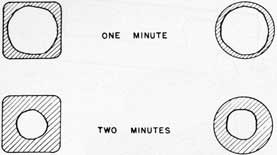
Molten metal in the corners of square or rectangular risers solidifies rapidly because of the large amount of surface area to which the metal is exposed. Figure 133 is a sketch showing that square risers are only as effective as an inscribed circular riser would be. The metal in the corners of square or rectangular risers is wasted.
There may be times when risers must be elliptical, square, or irregularly shaped where they join the casting, but they should be constructed in such a manner that they are cylindrical above the neck of the riser.
Riser Size. Practical foundry experience has shown that the most effective height of a riser is 1-1/2 times its diameter in order to produce maximum feeding for the minimum amount of metal used. Any riser higher than this is wasteful of metal and may be actually harmful to casting soundness. A riser having incorrect height and one with recommended height are shown in figure 134.
The problem of determining the correct riser diameter for feeding a given section is somewhat more difficult. A safe approximation is to assume that the riser has the same volume as the section it is to feed. As an example, a flat plate 1 x 4 x 8 inches has a volume of 32 cubic inches and a surface area of 88 square inches. The volume to area ratio (V/A) is 0.364. The riser necessary to feed this section will also have to have a volume of 32 cubic inches. Since the riser height is set at 1.5 times its diameter, the formula for the volume of a cylindrical riser is V = 3πr3. The solution of 32=3πr3 results in a radius of 1.5 inches. The riser then has a 3-inch diameter and 4.5-inch height. The volume to area ratio of the riser is 0.566, as compared to the casting V/A ratio of 0.364. As a result, the riser will solidify after the casting and should feed properly. These figures were computed for a side riser. The riser size may be changed slightly, depending on the experience gained with various castings.
Records of successful risering arrangements are useful in determining the size of the risers that feed various shaped sections correctly. Records that are used as a reference for determining riser size and location reduce the time necessary in making the mold and producing a good casting
Good and bad risering practice with respect to size and shape are shown in figures 135 and 136. Figure 135 shows a cylinder casting in which risers of excessive height and square shape were used. This casting was also over-gated. The yield on this casting was 43 percent. That is, only 43 percent of the metal
poured was in the casting. The same casting, with proper gating and risering, as in figure 136, had a 77 percent yield. Notice that the risers are round and that the height is approximately 1-1/2 times the diameter.
Riser Location. Heavy sections of a casting have a large amount of solidification shrinkage which must be compensated for from an outside source. Heavy sections, therefore, are the locations for risers. Figure 137 shows a cast wheel with top risers at the rim and spike junctions and at the hub. An important point to remember in the risering of a casting is that the hottest metal must be in the riser if it is to be effective. A rise ring arrangement that resulted in cold metal in the riser is shown in figure 138. This system produced a leaky casting when tested under hydrostatic pressure. When the gating and risering were changed so that the last and hottest metal was in the riser, as in figure 139, a sound casting was produced.
Another factor that must be remembered in risering is that it is impossible to feed a heavy section through a thin section. The thin section will freeze before the heavy section has completely solidified and a shrink will result. The diagram in figure 140 illustrates this. The two heavy sections are fed by their respective risers. The section on the right, however, has its heaviest part (C2) separated from the riser by a reduced section (C1). Section C1 will solidify and be fed from the riser C before part C2 has solidified. As a result, a shrink defect will be found at D. A method of preventing this defect would be to use a blind riser to feed the section at D.
Many times, a heavy section is so located in a casting that it cannot be fed with an open riser. In such a case, a blind riser is effective in feeding the section. Figure 141 shows a flanged casting which has been gated with an open riser. This type of riser location has the disadvantages that the riser is hard to remove from the casting and it is not possible to gate into the riser. This same casting is shown in figure 142 with a blind riser. It will be noticed that it is gated through the riser to make the best use of directional solidification and arranged to make removal of the riser easier.
Another point which must be considered in the location of a riser is that of the contact area of the riser and the casting. It must be remembered that the contact area of the riser must be large enough to permit feeding and small enough that it is not too difficult to remove the riser.
A good method for determining the size of riser necks involves the use of inscribed circles in roughly drawn sectional layouts as shown in figure 143. The maximum circle possible is
101
inscribed in the area to be fed, and its diameter determined. The diameter of the contact (B), should be at least 1-1/2 times the diameter of the circle inscribed in the casting (A). For contacts of rectangular shape, the minimum dimension should likewise be 1-1/2 times the diameter inscribed in the casting section. There is no need for having the contact diameter more than twice the diameter of the circle inscribed in the casting section.
TYPES OF RISERS
There are two general types of risers, the open riser and the blind riser. The open riser is open to the air while the blind riser is not cut through to the surface of the mold. A blind riser cannot be seen when the mold is closed.
Open Risers. Open risers are used widely because they are simple to mold. Their greatest use is in large flat castings which have numerous heavy sections.
Blind Risers. Blind risers are advantageous because:
1. They facilitate bottom gating into castings by feeding the hot spot at the point of entry of metal. Gating into the riser also preheats the riser cavity and promotes greater feeding efficiency as well as proper temperature gradients within the casting.
2. They can be located at any position in a mold to feed otherwise inaccessible sections.
3. They are more efficient than open risers because they can be designed to closely approach the ideal spherical shape, thus substantially reducing the amount of riser metal required for satisfactory feeding. In addition, they are completely surrounded by sand, which eliminates the chilling by radiation to the air and keeps the metal liquid longer.
4. They are easier to remove from castings than open risers because they can be more strategically positioned.
An idea of the relative efficiencies of open and blind risers may be gained from the fact that open risers do not usually deliver more than 20 percent of their volume to the casting, whereas blind risers deliver as high as 35 to 40 percent. For the same casting, blind risers can be made much smaller than open types.
Blind risers operate in fundamentally the same manner as the open type except that it is not necessary to place them above the casting in order to feed properly. In common with open risers, the molten metal they contain must be kept open to the atmosphere, in order that
atmospheric pressure may bear upon it, and proper feeding of the casting result.
Before discussing the means commonly used to keep blind risers open to atmospheric pressure, an explanation of the effect of this pressure on solidifying castings is necessary.
With metals solidifying as a continuously thickening envelope or skin, and contracting in volume as they freeze, a vacuum will tend to form within the casting, if the molten metal in the casting system (casting, risers, or gates) is not acted upon by atmospheric pressure, and if properly melted metal with a low dissolved-gas content is used.
Figure 144 illustrates the difference between keeping top risers open to atmospheric pressure and not keeping them open. Figure 145 shows the same condition for blind risers.
Figure 146 shows other fairly common types of casting defects attributable to this same phenomenon, which can be explained in the following manner. When the vacuum starts to form, the atmospheric pressure of 14.7 p.s.i. may collapse the casting walls, if they are weak enough, as shown in C, figure 147. It also may penetrate at a hot spot where the solidified skin is quite thin and weak. This usually occurs around a small core or at a sharp corner of the casting as shown in figure 146a and 146b. The importance of this effect cannot be overemphasized. It must be understood by foundrymen if their efforts are to be consistently successful, since its influence is felt in many ways in the production of castings.
The most successful method of introducing atmospheric pressure into blind risers involves the use of either a small-diameter sand core, or a graphite rod, placed in the riser cavity as shown in figure 147. A sand core is permeable enough to allow atmospheric pressure to enter and act on the last molten metal in the riser, which is at the center of the riser. Metal does not solidify rapidly around the sand core because it is small and does not conduct heat very rapidly. The cores are generally made of a strongly bonded oil sand and are reinforced with small wires or rods. The sizes used are as follows:
Risers up to 3-inch diameter-3/8 inch or 1/2 inch core.
Risers from 3-inch to 6-inch diameter-5/8 inch or 3/4 inch core.
Risers from 6-inch to 10-inch diameter-7/8 inch or 1-inch core.
The graphite rod has its best application in risers for steel castings although the sand
102
core is satisfactory. The graphite rod is not altogether impermeable but most of the atmospheric pressure enters along the outside of the rod. The steel in the riser absorbs the carbon of the graphite rod which lowers its freezing point by 100°F. or more, thus, keeping it molten longer. Because of this carbon absorption, and the small mass of the graphite rod, the metal does not solidify around it, thus, permitting the entrance of atmospheric pressure. The high-carbon area left in the riser makes it necessary to use care in the selection of the riser size to make sure it does not extend into the casting. This method can also be applied to cast iron. The graphite rod works as well as the sand core in all cases and has the advantage of greater structural strength. (CAUTION: When graphite rods are used in risers for steel castings and a dead-melting practice is followed in the Rocking Arc or Induction furnace, undissolved graphite rods should be picked out of the risers to avoid carbon pickup when these risers are remelted.) In general, the sizes of graphite rods used are as follows:
Riser Diameter
Graphite Rod Diameter, inch
Up to 3 inches
3/16
3 to 5 inches
1/4
5 to 8 inches
5/16
8 to 12 inches
3/8
Blind risers have an advantage in addition to those previously given; namely, they have the ability to feed sections of castings in positions higher than their point of attachment. For example, sections of steel castings as much as 30 inches higher than the riser contact have been fed by blind risers. These castings were made in a laboratory under ideal conditions, however, and such practices should not be applied in the production of emergency castings where there is no time for experimentation.
Theoretically, it should be possible for a blind riser, when properly kept open to the atmosphere, to force steel upward into a void to a height slightly greater than four feet. Actually, this cannot be done because a true vacuum never exists in even the best-made steel, some gas coming out of solution to partially fill the void. Further, to count upon a completely sound skin in every case would not be practical, there always being the danger of eroded sand, ladle slag, or local mold disturbances rupturing this skin and thus breaking the vacuum and the feeding system.
Figure 147 shows a layout for the use of a blind riser for feeding the heavy section of a casting. The sketch shows the casting actually seven inches higher than the top of the blind
head. In the manufacture of average castings, such as valves, this situation seldom exists. In general, the mass of the flange or other section is great enough to require a blind head very nearly as high as, or slightly higher than, the part it is to feed.
Referring again to figure 147, the metal poured into the ingate must flow first through the riser and then into the casting. As soon as the mold is completely filled, the metal loses temperature rapidly to the sand, and a skin of solid metal quickly forms at the mold-metal interface. This initial skin formation is shown as the cross-hatched areas of the figure. As temperature drops, more and more metal solidifies.
The atmospheric pressure acts like a piston on the metal in the blind riser, forcing it into the casting to feed shrinkage. In other words, the system is functioning on the principle of a barometer. Shrinkage is constantly tending to create a partial vacuum in the casting, and atmospheric pressure, acting through the medium of the molten metal in the riser, is constantly relieving it. If solidification proceeds properly with the parts most remote from the riser freezing first (cold metal in a cold mold cavity) and progressing thence toward the riser (hot metal in a hot mold cavity), each successive amount of shrinkage is compensated by additional fluid metal forced in from the riser. The ingate into the riser, being smaller than the neck leading to the casting, freezes off first and completes this part of the closed system.
Blind risers with pencil cores to produce atmospheric pressure on the molten metal in the riser work satisfactorily with most heavy metals. Blind risers may be used with light metals also, but the pencil core is not effective. Oxide films, formed on the surface of the molten light metals, prevent the pencil cores from functioning properly.
Use of Blind and Open Risers Together. When several risers are used at different levels in the same casting, it is essential that a particular zone of feeding be assigned to each riser. Figure 148 is a sketch showing the necessity for this precaution. The blind riser failed to function. A cavity was found in the casting in the position shown. The reason for this is that both risers were initially open to the atmosphere. The net advantage of the blind riser in this respect was zero. Because of the higher position of the open riser, the metal was forced through the system to actually feed the blind riser. By the time the narrow section of metal shown at (c) had solidified and shut off the hydraulic contact between the two risers, metal had solidified beyond the end of the sand core and made it impossible for atmospheric pressure to act. The
103
section to be fed further was choked at (c) and solidified with the shrinkage shown. It is to be noted that the sand core, had it been placed through the blind riser at a lower point, would have aided in preventing this.
The casting could have been made perfectly sound without changing the method of risering to any appreciable extent by either one of two methods. One method would be to place external metal chills cast to shape, around the neck of the casting at point (c). This would chill the metal at this point, separate the two heavy sections, and allow each riser to function independently of the other. The other method would be to apply hydrostatic pressure to the blind riser by extending it to the surface of the mold as an open riser. This would then have equalized the hydrostatic pressure in the two risers. The assignment of an independent feeding zone to each riser is a very important part of properly feeding castings.
VENTS
Vents are a necessary part of any system of gates and risers. The function of a vent is to permit gases to escape from the mold cavity fast enough to avoid developing back pressure which would oppose the inflowing metal. Vents also prevent gases from becoming trapped in the metal and forming gas cavities. Vents should be taken off all high parts of molds, such as flanges, bosses, lugs, and care should be taken to make sure that they are open to the top of the mold.
Experience has shown that round vents large enough to evacuate mold gases at a proper rate will frequently reveals fine shrinkage cavity in the casting when they are removed. Vents of rectangular section are preferred, and they should be kept comparatively thin so that the metal which flows into them will solidify quickly.
For small and medium castings, such as will be made for most emergency work, vents made by the use of molder's lifters or by a saw blade are satisfactory. This represents the desired thickness. It is better to use many thin vents than few large ones.
PADDING
Padding is used mainly in conjunction with risers to obtain directional solidification and is discussed here rather than under casting design. It is often possible to avoid the use of chills or extra risers by padding between heavy metal sections. If weight is important, or if the mechanical functioning of the part is affected, this padding is removed when the casting is machined. Figure 149 shows some typical cases in which padding is applied to avoid the use of chills or risers.
Padding is used to encourage directional solidification in members of uniform thickness. When used for this purpose, it is a tapered section of metal with the taper increasing in the direction of the feed heads. When uniform sections are made without padding, centerline shrinkage may occur. Uniform solidification in a member generally causes centerline shrinkage, but progressive solidification along the member gives a sound casting.
Uniform solidification can be prevented to a large extent by gating and risering, but in many cases this is not sufficient. Figures 150 and 151 show some typical applications of padding to obtain soundness or freedom from shrinkage.
Centerline shrinkage actually occurs on the thermal centerline of the member, since it is the last portion to solidify. Figure 152 shows where centerline shrinkage will occur in unpadded sections. In A, because of the lower heat-extracting capacity of the core completely surrounded by metal, the centerline shrinkage will be nearer the cored surface. To a lesser extent, this applies to B. In C, the thermal centerline will coincide with the section centerline.
The use of a special core to obtain padding is shown in figure 153.
When padding is used, it should be applied if possible on surfaces where it can be removed by machining.
HOT TOP AND ANTIPIPING COMPOUNDS
Methods of keeping top risers open to the atmosphere so that maximum feeding can be obtained are of great value to the foundryman. Materials which aid the foundryman in this respect fall into two classes: (1) insulating corn-pounds and (2) exothermic compounds.
Insulating Compounds. As the name implies, insulating compounds are used to insulate the riser and to reduce the heat lost by radiation to the air. They are usually spread on top of the riser after the pouring has been completed. Any of the commonly known insulating materials can be used. Examples of suitable materials are asbestos, sawdust, blacking, talc, and even dry sand. In unusual cases requiring small risers, insulating sleeves may be made from some of these materials and rammed into the mold to make the riser cavity. This procedure, along with insulating material on top of the riser, provides complete insulation of the riser. Care should be used to prevent excessive contamination of molding sands with these materials.
104
A comparison between an insulated riser and one not insulated is shown in figures 154 and 155. By good insulation of the top of a riser, it can be made smaller and still feed well. An important factor which must not be overlooked in the use of insulating compounds is that of absorbed moisture. Before using insulating compounds, they should be dried, especially if they are molded and rammed up in a mold.
Exothermic Compounds. Exothermic compounds are usually mixtures of aluminum with a metal oxide. When ignited by the molten metal in a riser, they burn and produce aluminum oxide, metal, and a large amount of heat. The reaction between aluminum and iron oxide in the thermite reaction for steel results in a temperature of 4,500°F.
The principal function of this type of compound is to supply heat to keep the riser molten longer. In the use of these compounds, a careful check should be made of their analysis to prevent any harmful elements from being picked up on later remelting. Because of the heat supplied by these compounds, shorter risers are required. A high riser will not permit the molten metal to feed properly and the desired effect will be lost. A comparison between an ordinary riser, an insulated riser, and one using an exothermic compound is shown in figure 156.
Carbonaceous materials may be used to produce better feeding in steel castings but the function is different. Some of the carbon in the material becomes dissolved by the steel in the riser. This lowers the melting point of the steel in the riser and it remains fluid for a longer period of time. There is a disadvantage to this type of riser compound; it produces an area high in carbon in the casting immediately below the riser, and this will produce variable carbon content when the risers are remelted.
CHILLS
When a heavy section of a casting is remote from a source of feed metal, and it is difficult to mold a riser in place, or hard to remove it in cleaning the casting, internal or external chills can be used to good advantage. Chills are metal shapes used to speed up the solidification in heavy sections, thus permitting the shrinkage that takes place to be fed through adjoining sections.
Chills are of two basic types, internal and external. Internal chills are cast into the casting and become a part of it. External chills are rammed up in the mold to form part of the mold surface and can usually be recovered for re-use.
INTERNAL CHILLS
It is difficult to set rules for the use of internal chills, their successful use being affected by many variables, such as chill composition, metal analysis, location, metal temperature, rate of pouring, chill surface, type of mold. In general, because of the many variables attendant to their use, they should be applied only in exceptional cases.
When used, their composition should be basically similar to the metal being cast; i.e., low-carbon-steel chills for steel and cast iron, copper chills for brass and bronze, and aluminum chills for aluminum.
Internal chills should always be very clean and dry. If they are not, gas will form as the molten metal surrounds them. This gas formation is the largest factor in the unsatisfactory behavior of chills. Oxide films, grease or oil, paint, mold washes, and moisture are all harmful. In green sand molds, the chills should not be placed until just before closing, and the mold should be poured immediately. If the mold cannot be poured immediately, it should be disassembled and the chills removed and kept dry. Internal chills should not be allowed to remain in molds during oven drying, since the fumes and moisture given off in drying will affect their surface adversely. Holes for receiving the chills should be made in the green mold, however, before it is dried.
The size of the internal chill is very important because its effect may prevent feeding if it is too large, and fail to accomplish anything if it is too small. The chill must fuse perfectly into the casting if soundness is to be obtained. Internal chills that are too large sometimes cause cracks in the cast metal.
The chill shape is very important. Figure 157 shows several types used in practice. By eliminating flat, horizontal surfaces and using surfaces which are streamlined, any gases formed are better able to rise and avoid becoming enveloped by the metal.
The location of internal chills is important. When used in bosses (a popular use for such chills), their location and size should be such that they will be completely removed in machining. Their location with respect to the metal flow in the mold is important. Internal chills placed directly in front of an ingate are quite likely to be melted and thus have no value, often being quite harmful. It is desirable to have some metal flow past a chill to wash away gases and aid in proper fusion. The amount of metal which will pass the chill must be considered in determining the size to use. Internal chills should not be used in sections which must be pressure tight
105
or which must withstand radiographic inspection and magnetic powder testing. Their use, even in the hands of an expert, is not always completely successful.
EXTERNAL CHILLS
The use of external chills is favored whenever it is necessary to increase the rate of solidification in any part of a casting. These chills may be cast to shape in either iron, steel, bronze, or copper, or they may be formed of plates, bars, or rods. Figures 158, 159, 160, 161, and 162 show some typical applications of such chills.
General rules to be followed in applying external chills can be summarized as follows:
1. Their surfaces should be clean and accurately fit the area to be chilled.
2. The ends and sides of large, massive chills should be tapered. Too drastic cooling at the edges of chills may form casting stresses resulting in cracks (See figure 163 ).
3. Chills should be large enough so that they don't fuse to the casting.
4. They should not be so large that they cause cracking of the casting or interfere with feeding.
5. The area of contact between chill and casting should be controlled (See figure 164). Note that in this figure, the chills on the left have a larger contact area with the casting than the chills on the right. As a result, the amount of metal solidified by the chills on the left is greater than the amount of metal solidified on the right. This can be verified by comparing the thicknesses of metal shown in the figure. This shows that contact area between the chill and the metal is very important in determining the effectiveness of a chill.
Rules 3 and 4 may usually be met by using a chill equal in thickness to that of the casting section being chilled. An increase in thickness over this will not appreciably increase the rate of solidification.
If the surface of a long chill is rough, the normal contraction of the cooling metal may be restrained and a crack produced in the casting.
A common use for external chills is in corners or parts which are inclined to crack
in the mold, due to contraction stresses. The use of brackets in preventing defects of this sort was previously discussed in Chapter 2, "Designing a Casting." Many times, brackets are of little help and chills must be used. By placing a chill in contact with such areas, the metal is more rapidly cooled to give increased strength at the time when the stresses would normally cause hot tearing of the casting.
In the discussion of casting design in chapter 2, it was mentioned that member junctions of L, T, V, X, and Y design which were inaccessible for feeding would be discussed further in this section. When designing such sections, fillets, must be kept to a minimum to avoid excessive increases in section thickness. In this regard, these sections differ from those which can be fed. With small fillets and the tendency to unsoundness in the center of the section, cracks are quite likely to be formed. External chills definitely reduce such defects (See figure 165 ). Figure 166 shows the preferred location of external fillet chills. This method also prevents cracking at the ends of the chills.
External chills applied to cast iron increase its solidification contraction and cause the iron in the chilled areas to become very hard. For these reasons, their use should be avoided in cast iron except in such cases where either of the above results is desired.
SUMMARY
It is difficult to consider or select gating, risering, and the use of chills separately because the three factors are interdependent. All three have a definite influence on each other and must be considered together if a sound casting is to be made.
A good gating system must supply clean metal to the mold cavity at a temperature and rate which will produce a casting free from defects. Risers must be capable of supplying hot molten metal to the casting to compensate for solidification shrinkage without causing any defects in the casting. Chills should be used only when necessary and then to assist in establishing proper temperature gradients within the casting.
In this chapter, no attempt has been made to discuss any problems relating to specific metals. Information on these metals will be found in following chapters dealing with the specific metals.
106
Figure 111. Parts of a simple gating system.
Figure 112. Illustration of gating ratio.
107
Figure 113. Gating nomenclature.
108
Figure 114. Unfavorable temperature gradients in bottom gated casting.
Figure 115. Defect due to bottom gating.
Figure 117. Reverse horn gate.
Figure 118. Reverse horn gate.
Figure 116. Bottom gate.
109
Figure 119. Bottom gating through side risers.
Figure 121. Sprue with well at base.
Figure 123. Pencil gate.
Figure 120. Bottom gating through riser with horn gate.
Figure 122. Simple top gating.
Figure 124. Typical parting gate.
110
Figure 125. Parting gate through the riser.
Figure 126. Whirl gate.
111
Figure 127. Simple step gate. (Not Recommended)
Figure 129. Complete mold reversal.
Figure 131. Pouring basin.
Figure 128. Thirty-degree mold manipulation.
Figure 130. Pouring cups.
Figure 132. Solidification time vs A/V ratio.
112
Figure 133. Effectiveness of square and round risers.
Figure 135. Poor riser size and shape.
Figure 137. Riser location at heavy sections.
Figure 134. Proper and improper riser height.
Figure 136. Proper riser size and shape.
Figure 138. Cold metal riser. (Not Recommended)
113
Figure 139. Hot metal riser.
Figure 140. Feeding through a thin section.
Figure 141. Flanged casting with open riser.
Figure 142. Flanged casting with bind riser.
Figure 143. Inscribed circle method for riser contact.
Figure 144. Effect of keeping top risers open.
114
Figure 145. Effect of keeping blind risers open.
Figure 146. Casting defects attributable to shrinkage voids and atmospheric pressure.
Figure 147. Blind riser principle.
Figure 148. Individual zone feeding for multiple risers.
115
Figure 149. Padding to avoid the use of chills or risers.
Figure 150. Padding to prevent centerline shrinkage.
Figure 151. Typical padding of sections.
Figure 152. Shrinkage on the thermal centerlines of unpadded sections.
Figure 153. Use of a core to make a padded section.
Figure 154. Effect of insulated risers.
Figure 155. Reduction in riser size due to insulating.
452605 0-58-9
116
Figure 156. Comparison of ordinary riser, insulated riser, and exothermic riser.
Figure 158. Typical external chills with wires welded on or in to hold chill in place.
Figure 157. Typical internal chills.
117
Figure 159. Use of external chills in a mold for an aluminum casting.
Figure 160. Use of external chills on a bronze casting.
118
Figure 161. As-cast aluminum casting showing location of external chills.
Figure 162. Gear blank mold showing location of external chills.
Figure 163. Principle of tapering edges of external chill.
119
Figure 164. Effect of chill mass and area of contact.
Figure 165. Typical application of external chills to unfed L, T, V, X, and W junctions.
Figure 166. Preferred method of applying external chills by staggering.
120
This page is blank.
121
Chapter VIII DESCRIPTION AND OPERATION OF MELTING FURNACES
OIL-FIRED CRUCIBLE FURNACE
Oil-fired crucible furnaces are satisfactory for melting aluminum, brass, bronze, other nonferrous metals and occasionally, cast iron, but will not get hot enough to melt steel.
CONSTRUCTION
Oil-fired crucible furnaces are of two basic kinds: the stationary type and the tilting type. The stationary type requires the crucible to be lifted in and out of the furnace. When a stationary furnace is recessed into the foundry floor or deck, it is known as a pit-type furnace. A pit-type furnace is shown in figure 167. In a tilting furnace, a crucible with a special lip is used, as shown in figure 168, and the molten metal is poured from the melting crucible by tilting the furnace. A typical tilting furnace is shown in figure 169.
A cross section of a stationary furnace is shown in figure 170. The furnace consists of four principal parts: (1) shell, (2) lining, (3) base block or pedestal, and (4) combustion unit. The shell is heavy-gage steel. The lining is usually a preformed, highly refractory unit which is cemented into place. The base block is used to support the crucible. The combustion unit is usually of the premixing type, which mixes the fuel oil and air for proper combustion. A tilting furnace has about the same general construction, except for the addition of a tilting device.
LINING THE FURNACE
The best linings are preformed and fired shapes of highly refractory material, such as high-alumina clay or silicon carbide bricks set into the furnace and cemented into place with a refractory cement. When the preformed linings are unavailable, a lining may be made by ramming in a suitable refractory.
A rammed lining can be made in an emergency from a stiff mixture of crushed firebrick, sand or gravel, 15 percent fire clay, and water. Thorough mixing is important; the mixture works better if it is made up a day ahead of time, rammed into a solid slab and then cut off with a shovel as it is needed for ramming. The crushed brick ("grog") or silica should be refractory, and of a suitable size. When using grog, successive layers should be rammed into place until the lining has been built up to the required thickness. Rammed around a form (as described below) is best. If no form is
available and successive layers have to be rammed against the furnace shell, one must be sure that each layer is roughened before the next is applied. Otherwise, the layers may separate later. If delays occur and the lining is allowed to dry out between layers, it should be thoroughly dampened before ramming is resumed. The finished lining must be dried slowly and completely before it is used.
There are also available heavy-duty plastic refractories which can be used to line furnaces of this type. Prepared mixtures of this type are preferred over those mentioned above. Water is added to the refractory mix to make it workable and then the lining is rammed in place around a form. Ramming mixtures containing the proper amount of moisture are also available. Care should be taken to center the form properly after the bottom has been rammed. The sides should be rammed into place by gradually building up the refractory around the form and roughening each layer before the next is rammed in. Heavy grease or aluminum foil can be used to cover the form to keep it from absorbing water from the refractory mix and to make it easier to draw the form. The proper thickness of lining can be obtained from the instructions supplied by the manufacturer of the unit. Always dry a new lining slowly and completely.
The proper thickness of lining should be maintained at all times by patching. When patching the lining, the patch should be undercut into the lining so that it is keyed into place as shown in figure 171. After the cavity has been made, it should be thoroughly dampened before the patch is rammed into place. The refractory mix should be made with the smallest amount of water possible. This will tend to minimize the drying shrinkage in the patch. The patch must be dried before the furnace is used. Proper maintenance of the furnace lining is necessary because a poor lining affects the combustion of the fuel in the furnace. Turbulence in the burning gases causes poor heating and melting takes longer.
Attention must be paid to the proper location of the burners with respect to the base block and the crucible. The burners should be directed into the chamber so that the center line of the burners is level with the top of the base block and so that the flame is directed between the furnace wall and the crucible. This is shown in figure 172. To obtain the best melting results from a furnace of this type, the size of crucible suggested by the manufacturer should not be
122
changed. With this practice, the volume around the crucible available for combustion will always be the same and more consistent furnace operation will result. It is better to melt a small charge in a large crucible than to melt the same charge in a smaller crucible that will cause a change in the operating characteristics of the furnace and possibly increase the time for melting.
Base blocks for crucible furnaces should be made of the same or similar materials as the crucible. The block must be refractory enough that it will not soften or slump at the operating temperatures of the furnace. If the block softens, it will stick to the bottom of the crucible and make the removal of the crucible difficult. If the block slumps, it will cause the crucible to tilt and possibly spill molten metal in the furnace, or in the case of the long-lip crucible, cause it to crack. Silicon carbide base blocks are preferred.
Along with lining upkeep, the care of crucibles must be taken into consideration for good furnace operation. Crucibles should be stored in a warm dry area. If proper storage facilities are not available, crucibles should be dried at a temperature of 300°F. for 8 hours before use. A gas-fired or oil-fired core oven should never be used to dry crucibles. Both of these fuels have moisture as a product of combustion. This makes the proper drying of crucibles difficult. If the precaution of carefully drying crucibles is not observed, any moisture retained in the crucible will cause cracking or spilling when the crucible is used. Soft-burned (unvitrified) clay-bonded crucibles should be annealed slowly before use for melting. The crucibles should be placed upside down in a cold or nearly c old furnace. NEW CRUCIBLES SHOULD NEVER BE PLACED IN A HOT FURNACE. The fuel is turned on with only enough air blast to bring the temperature up slowly until the crucible reaches a cherry-red color. It may then be carefully turned right side up, charged, and used in a melt down. Crucibles are very fragile, either cold or hot, and should be handled carefully at all times. Annealing is not necessary with vitrified hard-burned, clay-bonded crucibles and should be avoided with graphite crucibles.
Further important information on the proper care of clay-graphite crucibles is given on page 128 under "Electric Induction Furnace." These precautions should be used for crucibles of all types.
CHARGING THE FURNACE
Tongs and shanks used for handling crucibles should fit properly so as to avoid damage to the crucible. Proper fit for a pair of tongs
is shown in figure 173. Notice that the tongs clear the top of the crucible and that the blades bear evenly against the sides of the crucible. Whenever a crucible is handled with tongs, they should be gently lowered, NOT DROPPED, onto the crucible and centered vertically before gripping and raising the crucible.
When charging the crucibles, the remelt (such as gates, risers, and sprues) should be charged on the bottom and ingot material on top, providing that there is room enough for the ingot without exposing it to the flame. Do not overfill the crucible so that any solid metal sticks out of the furnace where it can pickup gas from the flame. When charging both scrap and ingots, care should be taken to prevent any of the charge material from becoming wedged in the crucible. Wedged material will expand when heated and crack the crucible. If ingot material cannot be charged with the scrap, it should be added after the first charge has started to melt. Ingot material should be preheated before charging so as not to chill the molten metal. Ingots or heavy pieces of metal should not be dropped or thrown into crucibles.
Whenever possible, a separate crucible should be kept for each type of metal melted. This reduces the possibility of contamination in successive heats.
Where it is impossible or impractical to keep separate crucibles for the various metals, the same crucible may be used only if a wash heat is made between the required heats. A wash heat consists of melting a scrap charge of the same composition as the desired heat. This wash is used to remove the undesirable metal that has penetrated the crucible and to prevent contamination of the following heat.
FLAME ADJUSTMENT AND FURNACE ATMOSPHERE
Fuel oil is usually supplied to the furnace at a pressure of 20 to 30 pounds per square inch. The air required for combustion is supplied by a blower at 16 ounces per square inch average pressure. All the air necessary for combustion should come from the blower and be thoroughly mixed with the fuel before entering the furnace. The introduction of secondary air around the burner nozzle is to be avoided because it results in erratic furnace operation. A proportional-mixer oil burner maintains a constant mixture of oil and air regardless of the volume of fuel being supplied to the furnace. This type of burner makes furnace control easier.
If manually operated fuel and air valves are used, extreme care should be taken to control the combustion of fuel. If too much air is used to make an oxidizing atmosphere, the
123
excess air will consume the carbon or graphite in the crucibles. If too much oil is used and a strongly reducing atmosphere is made, an excess of moist gases will be produced and will attack the crucibles and cause gas pickup in the melt. Careful control of an oil-fired melting furnace is an absolute necessity for good furnace operation for obtaining good service from the crucibles and for melting metal low in gas content.
The atmosphere in the furnace should be slightly oxidizing, that is, there should be just a little more air than is required to completely burn all of the fuel. when the furnace is operating under the correct slightly oxidizing atmosphere, a slight green tinge will appear around the outer fringe of the flame. A reducing atmosphere is usually indicated by a smoky, yellow flame. A quick test can be made by passing a freshly broken piece of virgin zinc through the open flame. If it turns black, the atmosphere is highly reducing. If it turns straw-yellow to light gray, the atmosphere is slightly reducing, and if it does not change color, the atmosphere is oxidizing. Another quick test is to throw a small block of wood into the furnace. If it burns with a flame, the atmosphere is oxidizing. If it chars slowly, the atmosphere is reducing and more air is needed at the burner.
MELTING AND TEMPERATURE CONTROL
Melting in an oil-fired crucible furnace should be as rapid as possible. The shorter the time the metal is held in the furnace, the less opportunity there is for excessive oxidation of the charge and absorption of gas by the molten metal. As soon as the charge is melted down, the temperature should be determined with an immersion pyrometer and repeated checks made until the desired temperature is reached. The flame should be cut back when measuring the temperature of prevent any damage to the thermocouple due to localized heating. It is generally necessary to shut off the fuel and air before the desired temperature is reached. The temperature of the metal in the crucible will continue to rise because of the heat retained in the furnace. The point where the fuel should be cut off will depend on the type and amount of charge metal and the operating characteristics of the furnace. The rise in temperature after the fuel and air has been shut off may vary from a few degrees to several hundred degrees. Considerable skill on the part of the melter is necessary to prevent over heating in this type of melting.
TAPPING
The tapping temperature should not be more than 100°F. above the desired pouring temperature. If the melting crucible is used for the
pouring operation, a properly fitted shank should be used. The crucible should be removed from the furnace with well-fitting tongs. Any pieces of slag or refractory which may stick to the crucible should be removed and the crucible set in a bed of dry sand. Any pieces of slag or refractory which are not removed will cause damage to the crucible.
The molten metal may also be tapped into a well-dried, preheated ladle for pouring. Any small additions of alloys may be added to the metal during tapping and should be placed in the bottom of the pouring ladle after about an inch of metal has been tapped into it. The alloy additions or material to compensate for melting losses should be added in small pieces so that they melt easily and do not produce hard spots in the castings.
After the heat has been poured, all slag and remaining metal should be drained and scraped from the crucible. Metal should never be permitted to solidify in a crucible. On reheating, the solidified button will expand and crack the crucible. If crucibles are not to be used immediately again, they should be cooled slowly, away from any draft.
ELECTRIC INDIRECT-ARC FURNACE
PRINCIPLE OF OPERATION
This furnace gets its name from the fact that the electric arc does not come in direct contact with the metal being melted. Any metal melted in the electric indirect-arc furnace receives heat from two sources. Radiant heat is obtained from the electric arc. A secondary source of heat comes from the refractory lining, which is heated by the arc. The rocking action of this type of furnace exposes more lining to the heat of the arc, which in turn permits the lining to deliver more heat to the metal. Rocking permits the lining to heat the metal and the metal to cool the lining. The melt-down time would be longer if the furnace were not rocked, and the lining would be damaged. Another advantage of the rocking furnace is the mixing action given to the molten metal. This produces a more uniform heat.
CONSTRUCTION
The construction of the furnace itself is fairly simple. It consists of a barrel-shaped steel shell with a heavy-duty refractory lining. The electrodes for supplying the necessary energy for melting are centered on the axis of the barrel. A charging door is provided on the front of the barrel. There is a special device supplied to rock the furnace automatically while it is in operation. An electric indirect-arc furnace installation is shown in figure 174.
124
ELECTRICAL SYSTEM
Power is supplied to the furnace from a transformer that "steps-down" the 440-volt current delivered by the generator to 100 volts. The reactance control, located on the transformer, serves to stabilize the arc. Electrode regulation and power in-put to the furnace is controlled on the power panel. A knife switch on the power panel is used to isolate the panel from the source of power or to permit power to pass from the source of power to the panel. The amount of current passing through the carbon electrodes is controlled by the load-adjusting rheostat. For more detailed information on the electrical system, refer to the manufacturer's literature.
LINING THE FURNACE
A preformed lining of mullite or sillimanite refractory is generally furnished for the electric indirect-arc furnace. The lining should be cemented into place with a highly refractory cement of the same composition as the lining; that is, either a mullite or a sillimanite cement. The life of a new refractory lining and the quality of the metal produced depend largely on the initial drying-out period. The following instructions should be followed in preparing a new lining for the first heat.
PROCEDURE FOR DRYING A NEW LINING
1. Place the lined barrel on the furnace rollers.
2. Fasten the automatic and manual electrode brackets.
3. Insert and clamp two new carbon electrodes. Make certain that they are properly aligned by introducing shims between the brackets and shell endplates. The electrodes should now appear as one continuous unit.
4. Wrap one turn of heavy wrapping paper around the electrodes and push the port sleeves in place.
5. Tamp the port sleeves in place with Alundum cement. Recheck the alignment of the electrodes.
6. Remove the paper and operate the electrodes manually over their full travel. No binding or sticking should occur.
7. Cut out the silicon carbide refractory door brick to conform to the contour of the furnace door and ram the spout and the space around the door with mullite or sillimanite refractory furnished with unit. The purpose of cutting away the door-brick refractory is to permit air to get into the barrel during the melting cycle.
8. Build a charcoal fire in the barrel. Allow it to remain for at least twelve hours. Clean out most of the charcoal at the end of that time.
9. Insert the stationary carbon electrode approximately 1-1/2 inches past the center of the barrel. Adjust the automatically controlled electrode so that it is approximately 1/2 inch from the stationary electrode. This practice should be followed on every heat, as it insures that the arc will be approximately centered during the melting cycle, thus, preventing damage to the end walls of the furnace lining.
10. Circulate the cooling water. This practice should be adhered to at all times prior to starting the furnace in order to prevent damage to the electrode clamps or any other jacketed parts. The temperature of the outlet water should never exceed 200°F.
11. Set the "Rocking Center" on the index mark.
12. Rotate the "Constant Rocking Period" knob until the "Range Pointer" is on the "off" position, which is full normal rock.
13. Close the d.c. electrode-motor switch. The closed circuit is indicated by the light on the d.c. contactor panel.
14. Place the arc-circuit toggle switch in the "on" position. Throw the circuit breaker in by means of the remote-control switch. This is indicated by the lights on the meter panel.
15. Push in the button marked "hand" on the regulator panel.
16. Advance the operating or automatically controlled electrode until it makes contact with the stationary electrode and strikes the arc. Withdraw the electrode rapidly until the kilowatt meter shows the desired rate of input. This should be less than the rated input of the furnace unit for the drying-out period. In general, a shortening of the arc increases the input rate and a lengthening of the arc by withdrawing the operating electrode decreases the input rate. Place the furnace on automatic control by pushing the button marked "automatic" on the regulator panel and make the necessary adjustments with the load-adjusting rheostat.
NOTE: Difficulty may be experienced in obtaining the desired, steady input on a green or cold lining when the furnace is started. lion automatic control, the unit tends to stabilize itself. However, hand adjustment of the operating electrode can be made until the input does not fluctuate excessively.
125
17. Place the rocking motor contactor b ox switch in the "on" position.
18. Place the "Automatic Rock" switch in the "on" position.
19. The drying-out period should be as slow as practical. The following schedule should not be exceeded. Apply the heat intermittently at:
(a) 6 kilowatt hours once each 1/2 hour for 2 hours.
(b) 9 kilowatt hours once each 1/2 hour for the next 2 hours.
Additional heat should now be applied continuously until the lining temperature reaches approximately 2700°F. (white heat). Turn the remote-control switch, arc-circuit toggle switch, and the d.c. electrode-motor circuit switch off and allow the lining to cool off to a dull red before removing the charging door. Loosen the electrode clamps and run the electrode back and forth in the port sleeve to remove any foreign matter and to prevent binding. If necessary, blow out the port sleeve with a compressed-air blast. The lining is now ready for its first heat, which preferably should be made the next day.
20. The next day, patch any cracks in the lining with a mortar cement refractory of the type used in cementing the preformed shapes. A general assembly view of the subject melting unit is shown in figure 175. The accessory equipment (gear) furnished with the unit for the preparation of the furnace for use is shown in figure 176.
Lining Repair. A carefully maintained lining is essential for the production of good quality metal. If slag or dross are allowed to accumulate in a lining, or a patch is placed over a slag area, a "choked" arc will result. Under such conditions, a poor quality melt will be produced. Therefore, it is necessary to remove all slag or dross from the lining before patching. Patching should always be deep and keyed in place. The patch material should be the same grade as the original lining. This is usually a mullite or sillimanite refractory. Patch the area around the furnace door and make up the spout daily. Port sleeves should be patched with Alundum cement daily and reamed to insure a tight electrode fit, without binding.
Shell Replacement. To change furnace shells, remove the electrode brackets and lift the shell off the furnace rollers. In replacing another shell on the furnace base, make certain the shell cam does not injure the limit switch.
Keeping the charging door in top-center position will minimize this possibility. Replace the electrode brackets and check the alignment of the electrodes.
Check the "limit" and "overtravel" switches to ascertain that they are improper adjustment. A mishap can be created by the use of the pushbutton with the "Automatic Rock" switch in the "on" position in checking the operation of the "overtravel" switch.
CHARGING THE FURNACE
Preheating. Preheat the lining with the furnace at full normal rock before charging the first heat. Note the starting instructions and precautions listed under "Procedure for Drying a New Lining." NEVER CHARGE METAL INTO A COLD FURNACE. The lining should preferably be preheated to the tapping temperature of the alloy to be melted. The approximate kilowatt-hour input necessary to preheat linings of various size units are listed below:
Furnace Type
Kwhr Required to Preheat
LF
60
LFC
80
LFY
115
AA
175
CC
275
CAUTION: Do not overheat the lining, as it will decrease the life of the refractory and introduce operating difficulties.
Charging. The ideal position for charging is with the furnace door in the top-center position. In any case, it should be within 45° of the top center position. Before charging, slide the electrodes back until they are flush with the furnace wall and will not be damaged during the charging period. The charging position should be varied from time to time to prevent excessive wear on one section of the lining.
First, charge foundry returns (gates and risers) which have been thoroughly cleaned of any excess sand. Excessive sand will cause a slag blanket to form on the surface of the molten metal during the melting cycle. This condition should be avoided, as it insulates the bath from the heat generated by the arc and will make it difficult to reach or determine the desired tapping temperature. Any unusually heavy pieces (such as large risers) should now be charged to the rear of the barrel. If borings of any kind are used in the charge, they should be added at this time. They will filter down through the foundry returns and give a more compact charge free from direct contact with the arc. Ingots are added to the charge last. Pile most of the charge toward the rear of the furnace so that a
126
larger angle of rock may be obtained with greater electrode safety. A properly charged furnace with electrodes in position for striking the arc is shown in figure 177. Charging should be accomplished as quickly as possible to prevent excessive loss of heat from the lining. (It is poor practice for an inexperienced operator to exceed the rated capacity of his furnace.) At this point, the furnace door is closed and clamped securely.
ROCKING MECHANISM
Adjust the rocking mechanism as follows:
1. Set the "Rocking Center" on the index mark. This synchronizes the furnace shell with the angle of rock.
2. Push in the button marked "Hand" on the regulator panel.
3. Set the "Range Pointer" and "Selector" on settings that will give the greatest angle of rock and permit the barrel to reach full normal rock as quickly as possible, and compatible with electrode safety. The "Selector" provides a means of changing the rate of the rocking angle. The no. 1 setting is the fastest and the No. 6, the slowest. The "Constant Rocking Period" knob provides a means of delaying the angle of rock. A "Nameplate Table" printed on the rocking controller assembly lists the time required for the barrel to reach full normal rock from various settings and charging positions. One distinct advantage of the rocking feature is the absorption of heat by the charge from the refractory lining. Thus, it is obvious that reaching full normal rock as quickly as possible will result in rapid melting, more uniform melt, lower power consumption, increase in refractory life, and a decrease melting loss. Actual settings of the "Selector" switch and "Constant Rocking Period" knob can best be determined through experience and will depend upon the physical position of the charge in the barrel. For the first heat, place the "Selector" in the No. 6 position and the "Constant Rocking Period" knob on the 20° rock setting. Delay the increasing angle of rock. Observe the heat closely and increase the rock manually as the heat progresses and the charge settles. After a few heats, the operator should be able to determine the most efficient and safe setting for any charge. Make certain that the "Selector" is placed securely in the notch intended.
ELECTRODE CONTROL
Center the carbon electrodes as follows. Insert the stationary electrode approximately 1-1/2 inches past the center of the barrel. Adjust the automatically controlled electrode so that it is approximately 1/2 inch from the
stationary electrode. This practice should always be followed on every heat as it insures that the arc will be approximately centered during the melting cycle, thus, preventing damage to the end walls of the lining. Make certain that the electrodes are not shorted.
Strike the arc manually. Advance the operating or automatically controlled electrode until it makes contact with the stationary electrode and strikes the arc. Withdraw the electrode rapidly until the kilowatt meter shows the desired rate of input. In general, a shortening of the arc increases the input rate and a lengthening of the arc, by withdrawing the operating electrode, decreases the input rate. Place the furnace on automatic control by pushing the button marked "automatic" on the regulator panel and make the necessary adjustments with the load-adjusting rheostat. Mark the setting for the normal operating input on the load- adjusting rheostat dial for future reference. Place the electrodes on automatic control by pushing in the push-button marked "Automatic" on the regulator panel.
Put the "Automatic Rock" switch in the "on" position. Observe the operating characteristics of the arc. It should be sharp and clear. The input should be steady and not fluctuating. A cloudy smoke arc from which small graphite particles are emitted is not a healthy operating condition for this unit and will result in casting losses due to porosity and low physical properties. This condition may be caused by low voltage across the electrode clamps or spongy electrodes. It may be corrected by increasing the voltage, decreasing the transformer reactance, or inserting good electrodes.
ELECTRODE PRECAUTIONS
Various steps that should be followed to provide good electrode operation are listed below.
1. Make certain that there is good contact between the clamp and the electrode.
2. Do not grip the electrode joints within the clamp as it may result in a broken nipple or a reduced area of electrical contact.
3. In joining two electrodes, insert the threaded carbon stud in the socket of one and screw in the other, finishing with a snapping action to insure good electrical contact. Do not use excessive force or the nipple will break.
4. Electrodes should be stored in a warm dry place to avoid sponginess. Sponginess will cause poor operating characteristics that will produce a poor-quality melt.
127
5. If an electrode breaks during the melting cycle, shut the furnace down and remove the broken section from the hearth immediately. Insert a new electrode.
6. When the nipple approaches the arcing end of the electrode, it should be broken off because it might slip off and fall into the hearth of the furnace and cause carbon pickup by the metal.
MELTING AND TEMPERATURE CONTROL
During the melting cycle, the charge should be observed periodically to check on the rate of meltdown and to make sure that it is melting satisfactorily. The angle of rock should be increased as quickly as conditions will permit. The initial melting will take place under the arc where a molten pool of metal will collect. As the angle of rock increases and melting proceeds, the pool will wash over the rest of the charge and make the meltdown faster. When the entire charge is molten, the furnace should be at full rock. Once the charge becomes completely molten, a close check should be kept on the temperature with either an immersion thermocouple or an optical pyrometer, depending on the metal being melted.
During the time the heat is being superheated to tapping temperature, it is important that the bath be kept clear of any slag or dross which may have formed. Any such substance not only prevents proper heating of the metal bath but also makes the determination of temperature difficult.
Various techniques used during meltdown for determining temperatures are described in the chapter s pertaining to the particular metals.
TAPPING
Just before tapping, the furnace should be operated at reduced input, just sufficient to maintain the temperature of the bath during the tapping period. Place the "Automatic Rock" switch in the "off" position. The furnace is now operated by the portable push-button station to carry it through the pouring stage.
Tapping should not be delayed once the proper temperature has been reached. If a slight delay is unavoidable, shut the arc off and set the "Automatic Rock" switch at "off." The temperature of the bath will not fall or rise appreciably during the first few minutes. If a longer delay is necessary, the furnace should be operated intermittently at reduced input and at full rock in order to maintain the desired temperature. The molten metal should always be tapped into a dried and preheated ladle.
After the furnace has been completely drained of molten metal, remove the door. With push-button control, roll the furnace barrel over until the charging- door opening is completely underneath. Allow the slag or dross to drain out by rocking the barrel back and forth or by applying the arc for a few minutes.
The barrel should then be returned to its original charging position and any slag removed from the spout. The spout may then be repaired by hot patching, if necessary. The electrodes are then run in and out to prevent binding by slag or metallic particles. The port sleeves should be blown or cleaned out. The furnace is then ready for another heat.
ELECTRIC RESISTOR FURNACE
PRINCIPLE OF OPERATION
The operating characteristics of the resistor furnace are different from those of the indirect-arc furnace. The indirect-arc furnace melts with a heat which is produced by the electric arc between electrodes. The resistor furnace produces the heat for melting by using continuous graphite resistors and no arc. The electric current passing through the resistors causes them to become heated to temperature sufficient to melt the charge. The principal is the same as that of an electric toaster.
CONSTRUCTION
The construction of the resistor furnace proper (including the rocking mechanism is the same as that of the electric indirect-arc furnace. The electrodes and electrical system have been modified to use resistor heating elements. The furnace uses two pairs of 1-3/4 inch-diameter resistors, which me et in the center of the furnace. They are seated and locked by spring tension from the electrode brackets. The use of male and female electrode sections permits easier withdrawal of the electrodes for charging or replacement. The resistors thread into a 4-inch-diameter terminal and form a reduced section, which in operation forms two continuous graphite bars through the melting chamber. A view of the furnace showing the resistors through the center of the barrel is shown in figure 178. The electrode-bracket assembly is shown in figure 179.
ELECTRICAL SYSTEM
The current for the resistor furnaces on repair ships is supplied by a 440/36 volt, 150-kva, 3-phase to 2-phase Scott-connected transformer. The input voltage is varied from 440 to 184 volts in 11 steps by means of solenoid-operated tap switches. This results in a variable
128
secondary voltage from 36 volts to 10 volts at the furnace terminals. Numerals on a disk visible through a circular window in the transformer housing indicate the nominal open-circuit voltage for each position. Taps can be changed under load. Push buttons on the control panel permit raising or lowering of the voltage and current on each phase so that the power input can be controlled at almost any level. During melting, the power input to the furnace is generally held at 150 kw.
LINING THE FURNACE
Lining of the resistor furnace and its repair are the same as for the electric indirect-arc furnace. For a description of the lining and its repair, see the section, "Lining the Furnace for the Electric Indirect-arc Furnace," page 124.
CHARGING THE FURNACE
The same precautions in charging are necessary with the resistor furnace as with the indirect-arc furnace (see page 123). The electrodes must be withdrawn until they are flush with the furnace end walls to prevent any damage during charging.
ELECTRODE CONTROL
Manipulation or control of the electrodes is not necessary during the melting operation. After the furnace is charged, the electrodes are run into the center of the furnace until they meet and form two continuous resistors. Once this is done, there is no further control necessary other than to make certain that there is always strong enough spring tension at the electrode brackets to maintain the resistors in position with good electrical contact. This avoids arcing at the joints.
MELTING AND TEMPERATURE CONTROL
Melting practice and temperature control are the same as for the electric indirect-arc furnace. (see page 123.)
ELECTRIC INDUCTION FURNACE
PRINCIPLE OF OPERATION
In the operation of the furnace, a high-frequency electric current is passed through the primary coil (figure 180), inducing a secondary current in the charge, heating it by resistance to the desired temperature. The charge may consist either of a single lump of metal or a quantity of loose pieces such as ordinary scrap. Even comparatively fine turnings can be melted successfully if a moderate amount of heavier
scrap is used. While high-frequency heating is effective over a wide range, about 1,000 cycles have been found to be the most practical for a 1-ton furnace. Smaller furnaces will require higher frequencies.
The heat is developed in the outer part of the charge and is quickly carried to the center by conduction, which is rapid through solid metals. After the charge starts to melt and a pool is formed in the bottom of the furnace, a stirring effect occurs. This not only carries heat to the center of the charge but accelerates melting by washing molten metal against the unmelted solid metal. It also mixes the charge thoroughly, thus assuring uniformity. The flow lines in the molten bath, indicated in figure 181 show there are no "dead spots" and that every part of the bath is moved. The vigor of the stirring can be controlled by varying the power input.
FURNACE CONSTRUCTION
The high-frequency induction furnace is essentially an air transformer in which the primary is a coil of water-cooled copper tubing and the secondary is the mass of metal to be melted. The essential parts of the furnace are shown in figure 182. The outer shell, "5," is made of asbestos lumber (transite is one brand of asbestos lumber) and carries the trunnions, "T" on which the furnace pivots in tapping or pouring. (Most of the shell has been cut away to show the section of the furnace.) The coil, "C," consisting of a helix of water-cooled copper tubing, is lined with a layer, "L," of refractory material, which forms a protective coating against metal leaks. This layer is continued above and below the coil against the asbestos support "R," the firebrick top, and base, "F." The coil lining and the firebrick bottom provide a cavity into which the refractory lining of the furnace is built. This lining may take the form of a thin-wall crucible or supporting shell, "M," packed into the cavity with granular refractory, "G," or it may be in the form of a sintered lining, which holds the charge or bath of metal, "B," and is molded at the top on one side to form the pouring spout, "D."
Due to the peculiarities in construction of the furnace, in which the primary coil is fairly close to the metal bath, the selection of suitable refractories is an important consideration. A typical electric induction furnace with a tilting mechanism is shown in figure 183. The power-control panel for this furnace is shown in figure 184.
ELECTRICAL SYSTEM
The high-frequency induction furnace receives its power from a high-frequency motor-generator set. Power to the furnace is regulated
129
by a control panel. The power put to effective use by the melting unit is very low, so capacitors are used to correct the low power factor and to permit the generator to produce full power. To make full power available during all the melting stages, tap switches are used to regulate the effective voltage on the furnace.
LINING THE FURNACE
There are two materials used in the lining of these furnaces in addition to preformed and fired crucibles. These materials (Norpatch and Normagal) are furnished by the furnace manufacturer. Norpatch is a refractory cement, while Normagal is a granular refractory material.
Lining the Furnace Coil. The furnaces are shipped with a 3/8 inch lining of Norpatch installed on the inside of the coil. This lining prevents the dry furnace-lining materials from leaking through the coil turns and protects the coil from serious damage by the molten metal in case of a lining failure. Each time a new crucible or lining is placed in a furnace, the coil lining should be examined for cracks. If small cracks are present, they should be filled in with a brush coat of Norpatch mixed with water to a consistency of heavy paint. If large cracks or holes are present, they should be patched with the Norpatch moistened with water to a thicker consistency, rammed in place, and smoothed with a wet brush or trowel.
When it becomes necessary to install a new coil lining, all the old Norpatch should be removed from the coil. A new batch of Norpatch is then mixed with water, making certain all lumps are well pulverized. This is applied to the inside of the coil with the hand or a trowel to a thickness of 3/8 inch. The Norpatch is pressed firmly between the coil so that it squeezes through to the outside, which provides a suitable anchorage.
After the entire inside surface has been covered, it is good practice to scrape off the high spots with a straight edge and fill in the low spots. This coating should be reasonably smooth and uniform. A 1,000-watt strip heater or the equivalent placed in the furnace permits the lining to dry slowly. Drying should take about 30 hours, and when complete, the cracks should be filled in as explained above.
Crucibles. The temperatures involved in the melting of nonferrous metals are not sufficient to sinter a monolithic lining. Therefore, preformed clay-graphite crucibles are used. In installing crucibles, the first step is to turn on full water pressure and then check for leaks in the coil and hose connections. Moisture will cause short circuits (possibly explosions) if it comes in contact with molten metal.
A good grade of dry silica sand (or the material "Nor sand" furnished by the furnace manufacturer) is tamped solidly in the bottom of the furnace to a depth of 3 or 4 inches. The thickness of the sand layer is adjusted so that when the crucible is placed on this lining, the top of the crucible is 1-1/2 to 2 inches below the top of the furnace. The space at the top is left for top patching. The crucible is centered in the coil and held in place by three wooden wedges between the coil and the crucible.
The sand is then placed around the crucible to a depth of 4 or 5 inches and tamped solidly in place to prevent pockets and to insure good contact between the crucible and the coil lining. This procedure is continued until the sand level is near the furnace top before the wedges are removed.
Norpatch cement, mixed with water to a ramming consistency, is then trowelled in place between the top of the crucible and the furnace shell. The pouring lip is also formed at this time. The cement seal and lip are slowly but thoroughly dried and the furnace is ready for operation.
Care of Clay-Graphite Crucibles. Proper care of clay-graphite crucibles will materially increase their life. Before use, they should be stored in a warm, dry place. A rack should be provided so that they will not be placed on a wet or damp floor and they should be stored bottom side up to prevent accumulation of moisture. Before using, crucibles should be heated to about 300°F. for approximately 8 hours to be sure all moisture is removed. If the preheating is not done, a sudden application of heat will crack them. After being rammed in place, it is good practice to heat crucibles (1) by means of a large electric bulb placed in the bottom of the furnace, (2) by use of an ignited charcoal pot in the crucible, or (3) by charging with a few pieces of carbon of sufficient volume to provide radiated heat when the furnace switch is on low.
After each heat, all excess metal clinging to the sides and bottom of the crucible should be removed. Care should be taken not to exert too much pressure, as the crucible tends to become brittle at high temperature. It is then checked for cracks of sufficient size to allow metal to leak through. Small hairline cracks will not give trouble as they will be sealed by the next heat when the pot expands.
At the end of the day's run, or particularly if there is along period between heats, the crucible should be covered to allow it to cool slowly, as fast cooling tends to develop cracks. Water should be allowed to run through the cooling system until the crucible has reached room temperature.
130
Crucibles which have worn down to 5/8-inch wall thickness are unsafe for further use, and should be replaced. Relining of the furnace requires that the old crucible and lining be removed-- sometime s, by hammering and chiseling. Care should be taken to preserve the refractory cement next to the coil. If it is damaged, it should be repaired before relining.
Rammed Linings. The use of monolithic linings for ferrous metals (iron and steel) is generally favored because of their long life and because steel cannot be melted in a clay-graphite crucible. Also, the steel will absorb carbon from the crucible. Cast iron, however, can be safely melted in a clay-graphite crucible.
Because of the difficulty of installing monolithic linings, the allowance list for each base and shipboard foundry includes magnesia crucibles in addition to materials for installing the monolithic lining. Magnesia crucibles are relatively fragile and must be handled with great care before installing and during use. The same general practice given for the clay-graphite crucibles should be carefully followed in installing them.
Although considerable skill and experience are necessary to properly install a monolithic lining for melting ferrous metals, if the instructions given below are carefully followed, a fair measure of success should be attained after the first two or three linings. Also, the experience thus gained should be sufficient to correct all faults which become apparent.
The first step consists of firmly ramming 5-1/2 inches of Normagal in the bottom of the furnace. This is most effectively done by the use of a rammer formed by welding along handle to a steel disk 5 or 6 inches in diameter.
Next, the asbestos form, supplied by the manufacturer, is prepared. This is done by drilling four evenly spaced holes about 1/8inch diameter in the disk about 1/2 inch from the edge. Directly opposite, four similar holes are drilled in the sleeve about 1 inch from the bottom. The disk is then fastened to the sleeve by the use of soft iron wire.
This form is next placed on the Normagal bottom and accurately centered. A weight of several hundred pounds is placed on the inside to prevent its shifting while ramming the sides. If the form is not centered at the top, it is because the bottom is not level, and proper adjustment should be made. About 3 inches of Normagal is then placed around the form and rammed uniformly and hard with a suitable hand rammer, followed, if possible, by an electric or air rammer. This practice is continued until the Normagal is within 5 or 6 inches of
the top of the furnace. It is then sealed and the spout formed with Norpatch cement, trowelled firmly in place and thoroughly dried.
An alternate and popular method involves the use of a steel form as shown in figure 185. When the charge becomes molten, the steel shell melts, the asbestos fluxes to forma slag, and the lining material is properly sintered. The first heat in a monolithic lining must be steel, as cast iron does not properly sinter the lining. The quality of a monolithic lining depends largely upon proper ramming of the lining material and the importance of this cannot be overemphasized.
The thickness of the lining must be carefully controlled and maintained during use, since it has a major bearing on the power consumption and melting speed of the furnace. Thin linings give better "coupling" (more induced power in the charge) than thick ones. A perfect coupling would be obtained if the charge were the same diameter as the coil. Naturally, this is not possible, so a satisfactory compromise must be obtained.
After each heat, the furnace should be drained completely of metal and slag, and all holes should be carefully patched. (No attempt should be made to patch over steel or slag). In general, all patching below the metal line should be done with Normagal mixed with sodium silicate, and patching above the metal line should be done with Norpatch mixed with water.
To reline the furnace, the old lining is removed as in the case of clay-graphite crucibles by hammering and chiseling, care being taken to preserve the refractory cement on the coil. The unsintered Normagal should be saved, since it can be used again in relining. If the refractory cement on the coil is intact, the furnace is relined in the manner previously described.
CHARGING THE FURNACE
The charge is preferably made up of carefully selected scrap and alloys of an aggregate composition to produce as nearly as possible the composition desired in the finished metal. Final additions are made to deoxidize the metal or to adjust composition.
The heavy scrap is often charged first, and as much of the charge as possible is packed into the furnace. The current is turned on, and as soon as a pool of molten metal has formed in the bottom, the charge sinks and additional scrap is then introduced, until the entire charge has been added. The charge should always be made in such manner that the scrap is free to slide down into the batch. If the pieces of the charge
131
bridge over during melting and do not fall readily into the molten pool, the scrap must be carefully moved to relieve this condition. Severe poking of the charge must be avoided at all times, however, because of danger of damaging the furnace lining. Bridging is not serious if carefully handled, but if allowed to go uncorrected, overheating of the small pool of metal may damage the lining seriously and will have a deleterious effect on the composition of the metal.
The compactness of the charge in the furnace has an important influence on the speed of melting. The best charge is a cylindrical piece of metal slightly smaller in diameter than the furnace lining. This will draw very close to the full current capacity of the equipment. Two or three large pieces with considerable space between them will not draw maximum current, since the air cannot be heated by induction. The charge should not be so tightly packed that upon heating and expanding it cracks the crucible or lining.
SINTERING THE MONOLITHIC LINING AND MAKING THE FIRST STEEL HEAT
After the furnace has been lined, a suitable charge of low-carbon scrap or Armco iron, consisting of pieces weighing between 1/4 pound and 2 pounds, should be selected and placed in the asbestos liner in such a manner that the charge will be reasonably compact. This charge should be brought to the top of the asbestos liner. Long or irregular shaped pieces should not be used for this initial charge, as such pieces may become bridged and prevent the solid metal from coming into contact with the bath as the melting progresses. Before the power is applied, it should be ascertained that water is flowing through all coils which are to be energized.
The many precautions to be observed in the first heat in a new lining are: (1) the charge should be brought to the top of the Normagal lining when molten, and (2) the metal should be held at 3,000°F. for 15 to 20 minutes to permit proper sintering of the lining. Neither of these practices should be followed in later production and are only necessary initially to secure a well-sintered lining.
MELTING AND TEMPERATURE CONTROL
As soon as the charge is completely melted and refining or superheating operations finished, further necessary additions of alloys or deoxidizers are made. The furnace is then tilted to pour the metal over the lip. If the entire heat is poured into a large receiving ladle, the power is turned off before tilting. If, however, the
metal is taken out in small quantities in hand ladles, power may be kept on while pouring. This maintains the temperature of the bath and facilitates slag separation by keeping it stirred to the back of the bath. When the heat is poured, the furnace is scraped clean of adhering slag and metal and is then ready for the next charge.
Because of the convexity of the bath surface resulting from the induced current, it is difficult to keep a slag blanket on the metal and usually, no attempt is made to do so. Should a slag blanket be desired, it is necessary to control the degree of convexity of the bath, which can be done by controlling the rate of power input to the melt.
It is important that dissimilar metals not be melted in the same lining or crucible. When melting cast iron or steel, the lining absorbs iron. Brass or bronze subsequently melted in the same lining will become contaminated with iron. The reverse will also be true; cast iron or steel can become contaminated with copper, tin, or zinc. If it ever becomes necessary to melt dissimilar metals in the same furnace, a wash heat similar in composition to the next heat planned can be used to cleanse the crucible. It is always better practice to have separate furnaces or linings for use in such emergencies.
The methods of melting nonferrous alloys vary considerably for different compositions. Questions often arise regarding which metal to melt first, the temperatures at which the additions of other metals are made, the use of slags and fluxes, deoxidation practice and pouring temperatures. Frequently, several alternative procedures are available for melting the same metal. For melting specific metals, refer to the later chapters dealing with each metal.
TEMPERATURE CONTROL
Temperature control in the induction furnace is measured by an immersion or optical pyrometer, depending on the metal being melted. The power should be reduced (or better, shut off) while taking a temperature reading with an immersion pyrometer to prevent an incorrect reading. Good melting records with proper temperature readings can prove useful in the event there is a failure in pyrometer equipment. If temperatures and power input are recorded during various melting operations, the power input, along with the time at a given power input, can prove useful in making a close approximation of the temperature of the heat.
SUMMARY
The operation of assigned melting furnaces is relatively simple and even inexperienced
452605 0-58-10
132
personnel can use them to melt metal. Whether this metal will make a good casting is another matter. For a strong, sound casting free of defects, it is necessary that the metal be melted under proper conditions and handled properly. It is relatively easy to see whether a metal is hot enough to pour into a particular mold, but it is hard to see when the metal has been damaged by improper melting methods. This shows up when the casting is shaken out of the mold.
Oil-fired crucible furnaces are convenient for melting nonferrous metals (brass, bronze, or aluminum) but usually are not satisfactory
for iron or steel. The quality of the metal can be damaged severely by improper furnace atmosphere, melting so that the flame hits some of the metal, or by using crucibles which have not been stored and prepared properly. CRUCIBLES AND FURNACE LININGS ARE AN ALL-IMPORTANT ITEM IN ANY FURNACE. They must be thoroughly dried before they are used for melting. If not, the damage they will cause to the metal will be more far-reaching than possible damage to the lining.
Electric furnaces are fast, clean and convenient. They also permit high temperatures to be reached.
133
Figure 167. Pit-type crucible furnace.
Figure 168. Crucible for tilting crucible furnace.
Figure 169. Tilting crucible furnace.
Figure 170. Cross-section of a stationary crucible furnace.
Figure 171. Undercutting a refractory patch.
134
Figure 172. Proper burner location.
Figure 173. Proper fit for crucible tongs.
Figure 174. Electric indirect-arc furnace.
Figure 175. General assembly view of electric indirect-arc furnace.
135
Figure 176. Accessory equipment for electric indirect-arc furnace.
Figure 177. Properly charged electric indirect-arc furnace.
Figure 178. Electric resistor furnace.
136
Figure 179. Electrode-bracket assembly for electric resistor furnace.
Figure 180. Cross section of electric induction furnace.
Figure 181. Flow lines in an induction furnace melt.
137
Figure 182. Essential parts of an induction furnace.
B - Metal bath
L - Protective refractory or insulation
C - Coil
M - Crucible
D - Pouring spout
R - Asbestos support
F - Firebrick
S - Outer shell
G - Refractory
T - Trunnions
Figure 184. Induction-furnace control panel.
Figure 183. Typical electric induction furnace.
Figure 185. Method of lining induction furnace using a steel form.