As explained in the opening chapter of this pamphlet, when a torpedo has been loaded into the
tube and the breech door is closed and-locked, the
tube is flooded with water to equalize the pressure
inside the tube with the pressure from outside, so
the muzzle door and shutter may be opened against
the resistance of the sea water outside. The tube is
flooded from tanks within the submarine. As the
tube is being flooded, the air from the tube is vented
through the forward and after vents. After the torpedo has been launched from the tube, the muzzle
door and shutter are closed, and the water which
has entered the tube is drained off. As the water
is being drained off, air is blown into the tube
through the vents, forcing the water out by filling
the tube with air.
The tube flood and drain system provides the
means for this flooding, venting, and draining of
the tube, before and after firing a torpedo.
Variations will be found in the tube flood and
drain systems on different submarines, and for detailed information pertaining to the installation in
any particular vessel, reference should be made to
the plans as well as to the General Information book
supplied to each vessel. The purpose here is to give
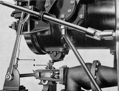
Figure 214 The tube drain
valve with operating lever in valve open
position.
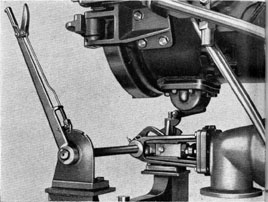
Figure 213 The tube drain
valve, with operating lever in valve closed
position. (A) Operating lever; (B)
Valve; (C) Lead to drain.
116
the basic principles of operation of the system. Once
thoroughly familiar with the fundamentals, the student of submarine operation should readily recognize any changes he may encounter on submarines
to which he may be assigned.
A typical tube flood and drain system consists of
drain, vent, and blow valves, these being arranged
in manifolds; also piping, and the related interlocking mechanism, the latter having already been described in detail in Chapter 4, in the section dealing
with the Tube Flood and Drain Interlocking Mechanism, on page 42 of this pamphlet.
There are two drain lines for each tube, forward
and aft, these leading to the drain and flood manifold. The manifold controls flooding and draining
tubes from or to the trim line, trim tank, torpedo
compensating tank, or W.R.T. (water round tube)
tank.
Each tube has two vent and blow connections,
one toward the breech end, the other toward the
muzzle end, these leading to an individual vent and
blow manifold. The manifolds have a three-way
plug cock to the blow and vent line from each tube,
a three-way plug cock to the blow and vent line
from the W.R.T. tank, and a stop valve to the
200-pound air service line.
Each tube is vented inboard by means of the
three-way plug cock connection to the blow and
vent line from the tube. When this connection is
in the blow position it permits blowing the tube
from the 200-pound air service line. When it is in
the vent position it permits venting the tube through
another three-way plug cock valve, which permits
venting inboard through a two-inch line, or outboard through a one-inch line which is clear of
the bow buoyancy tank. The tube is vented outboard
only when it is believed that noxious gasses or
vapors are present in the tube.
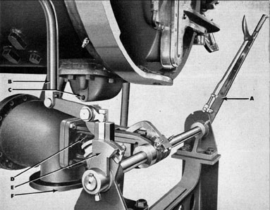
Figure 215 The drain valve, view from
the side opposite to that shown in Figures 213 and 214, showing (A) Valve
operating lever, in valve open position;
(B) Rod extending down from the interlock lever to interlock collar; (C) Connection for pipe to drain roller bracket
(one of four); (D) Valve; (E) Interlock
collar on stem of valve operating lever;
(F) Connection to drain.
117
FLOODING THE TUBE
The procedure for flooding the barrel, preparatory
to opening the muzzle door after a torpedo has
been loaded into the tube, is as follows:
(a) The breech door must be closed and locked,
as described in Chapter 3, see Figure 33, page 28.
(b) The tube is then vented, either inboard or
outboard as determined necessary.
(c) The drain valve interlock lever is moved to
"Muzzle Door Closed" position, as described in
Chapter 4, see Figure 77 on page 42.
(d) The W.R.T. tank and barrel drain valves are
opened.
(e) Blow the W.R.T. tank until the tube is
flooded.
(f) Close the W.R.T. tank, barrel drain, and
tube vent valves, and vent the W.R.T. tank until
the gage shows atmospheric pressure.
To flood a tube from the trim tank, the trim
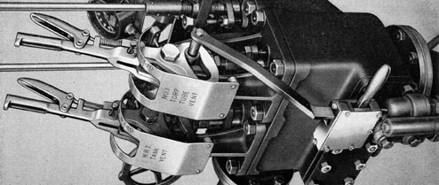
Figure 216 The W.R.T. (water round tube) tank vent lever, the one at the left, shown in open position.
Figure 217 The W.R.T. tank vent lever, shown in closed position.
118
DRAINING THE TUBE
tank blow and vent valves are used instead of the
W.R.T. tank valves. To flood a tube from the sea,
the trim pump, trim line valve, and the tube vents
are used.
For draining the barrel after a torpedo has been
launched, the procedure is as follows:
(a) The firing interlock lever is moved to the
"Muzzle Door Unlocked" position, as described
in Chapter 4, see Figure 81 on page 44.
(b) Close the impulse stop valve, if one is installed on the tube.
(c) Close the muzzle door.
(d) The drain valve interlock lever is moved to
"Muzzle Door Closed" position, as shown in Chapter 4, see Figure 77 on page 42.
(e) Open the barrel drain valve.
(f) Open the W.R.T. tank valve in the drain
manifold.
(g) Vent the W.R.T. tank.
(h) Blow the barrel until free of water.
(i) Close the tank vent.
(j) Vent the tube until the gage shows atmospheric pressure in the tube.
Note-In submarines of the Portsmouth design,
to drain a tube to the trim tank, the trim tank drain
and vent valves are used instead of the W.R.T. tank
valves. To drain to the sea, the trim pump, trim
line valve, and the tube vents are used.
In submarines of the Electric Boat Company design, a W.R.T. tank overflow valve to the trim tank
is provided for the purpose of blowing the tubes to
the trim tank when the W.R.T. tank is full. An
interlock to close a quick operating valve in the
W.R.T. tank blow line when the overflow valve is
open, prevents accidental blowing of the W.R.T.
tank to the trim tank. A loop around the quick
operating valve is provided with a check valve for
venting purposes. When the overflow valve is closed,
normal blowing and venting of the W.R.T. tank
is accomplished, and, when the overflow valve is
open, water from the tube is transferred to the trim
tank by way of the W.R.T. tank.
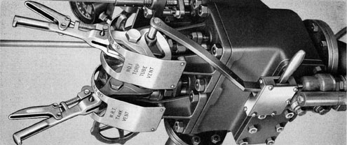
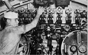
Figure 218 Venting the tube (first vent to right).
Figure 219 Venting the W.R.T. tank.
Figure 220 Flooding the tube from the W.R.T. tank.
119
ROLLER BRACKET DRAINS
The roller brackets, of which there are four on the
under side of the tube-these brackets containing
the rollers on which the torpedo rides as it passes
through the tube-are drained by three-eighths inch
I.P.S. lines to the tube drain line (see C in Figure
215, page 117) entering that line above the drain
valve, i.e., between the tube and the drain valve.
These drain lines from the roller-brackets must
be kept free of any obstructions. This is important
inasmuch as the shell of the torpedo is steel, and
the tube barrel rollers with their associated parts
are principally bronze, hence the presence of sea
water in the roller bracket pockets may cause
galvanic action, with resulting pitting and corrosion
of the torpedo. In order to prevent this, the installation of phenolic compound rollers in late vessels
has been authorized, to facilitate extensive service
test. If successful, such rollers will be issued to all
submarines.
Where bronze rollers are installed, pieces of zinc
may be placed in the roller brackets to minimize
electrolytic corrosion. As the zinc is electro-positive
to both steel and bronze, it should be attacked by
the sea water instead of the steel or bronze. These
pieces of zinc should be inspected regularly and
renewed whenever necessary.
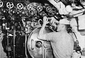
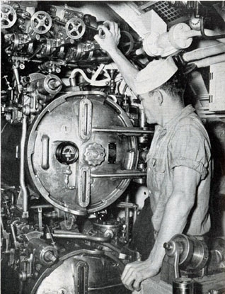
Figure 221 The No. 1 tube blow
valve-watching water level gage
preparatory to closing the tube blow
valve.