Tube Drain Valve and Muzzle Door Interlocking Mechanism
42
Firing Interlocking Mechanism
44
Interlock Disconnect
46
37
BREECH AND MUZZLE DOOR INTERLOCK
FOREWORD: Plate Two, which shows diagrammatically
the complete interlock system for a torpedo tube
having a manually-operated muzzle door mechanism, and Plate Three, which similarly pictures one
for a tube having a power-operated muzzle door
mechanism, should be referred to in connection with
the more detailed figures and text of this chapter.
In general, the differences between the interlock
systems are:
(1) The interlock slide, which is moved fore-and
aft by threads on the muzzle door operating shaft
in the manually-operated mechanism, is driven by
gears, sprockets and a chain from the operating
shaft of the power-operated gear.
(2) In the manually-operated mechanism the
breech and muzzle door interlock lever (A in
Figure 70, or F in Figure 72) is operated by hand,
independently of other gear. In the power-operated
mechanism, the breech and muzzle door interlock
lever is linked to the drain valve and muzzle door
interlock lever by a connecting rod (A in Figures 74
and 77) so that the two operate together.
(3) In general, the interlocking bolts operate with
the interlock slide in the same manner, regardless
of whether the muzzle door operating mechanism
is of the manual- or power-operated type. However,
in order to properly control the operation of the
control valve in the power-operated type, the interlock bolts engage the thrust rod or attached parts
as well as the interlock sleeve. Also, in the power
operated type, these bolts do not prevent the operation of the emergency hand drive, so additional
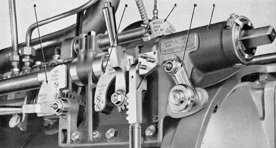
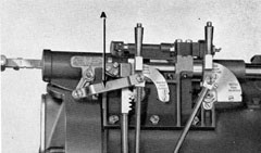
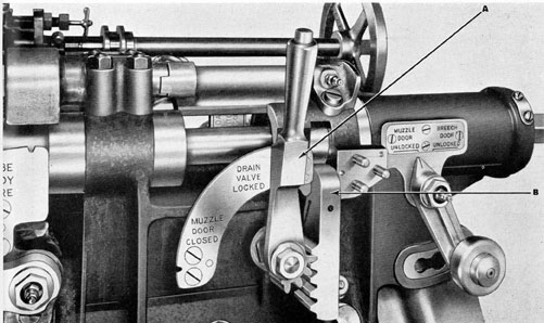
Figure 68 The breech bracket and interlocking levers,
showing their position with relation to the breech door.
(A) Firing mechanism interlock lever; (B) Tube drain
valve and muzzle door interlock lever; (C) Indicator
showing position of muzzle door while opening and closing; (D) Breech and muzzle door interlock lever; (E)
Breech bracket, in which the cylindrical slide moves as the
muzzle door operating shaft is turned.
38
linkages are provided from the breech and muzzle
door interlock lever and from the firing interlock
lever to the hand operating shaft, each linkage consisting of a long connecting rod and a bellcrank
lever which has a tip shaped like a gear-tooth so
that it will engage a gear which is keyed on to the
hand operating shaft. These linkages perform the
same functions with respect to the emergency hand
shaft that the interlock bolts perform with respect
to the power-operated gear.
In this chapter, Figures 68 to 73, 77, 79, 80 to
depth and speed spindles are retracted from their
sockets in the torpedo, (4) the firing stop valves are
locked open, (5) the drain valve is locked closed.
The interlocking mechanism consists of three sections: The Breech and Muzzle Door Interlock; the
Tube Drain Valve and Muzzle Door Interlock; and
the Firing Mechanism Interlock. The levers and indicators for these interlocks are shown in Figure 68.
In general, the interlocking mechanism is mechanical throughout and centers about the muzzle
door operating shaft, which extends (in the manual
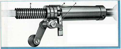
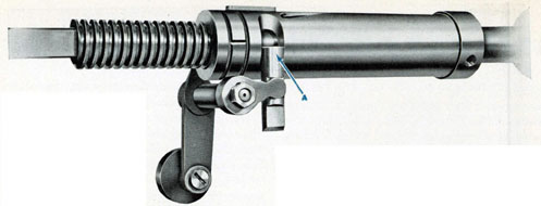
Figure 69 Cylinder slide and breech end of
muzzle door operating shaft, showing (A)
Acme thread on breech end of muzzle door
operating shaft; (B) Slot for breech and muzzle door interlock bolt; (C) Bolt disengaged
from and in line with slot in slide, in muzzle door
unlocked position.
83, and 85, strictly apply only where muzzle door
operating mechanisms are of the manual type.
Figures 74 and 75 apply where the power type is
installed. Figures 76, 78 and 84 may be considered
illustrative for either type.
The interlocking mechanism actually is protection against improper operation of the tube. It
prevents (a) opening the breech door when the
muzzle door is open, and opening the muzzle door
when the breech door is open; also, it prevents
(b) opening the drain valve when the muzzle door
is open, and opening the muzzle door when the
drain valve is open. It prevents (c) firing of the
tube except when (1) the muzzle door is locked
open, (2) the breech door is locked closed, (3) the
Figure 70 Breech bracket, showing breech and muzzle
door interlock lever (A) at muzzle door unlocked position.
39
Figure 71 Cylindrical slide, showing (A) interlocking bolt
raised into slot, preventing movement of slide and locking muzzle door operating shaft.
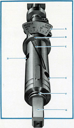
Figure 73 Cylindrical slide disassembled, showing (A)
Muzzle door indicator; (B) Ring with pointer and tooth
in (C) Helical groove in cylindrical slide; (D) Slot for
head of drain valve interlock rod; (E) Slot for breech
and muzzle door interlock bolt; (F) Acme thread on
(G) Breech end of muzzle door operating shaft.
type) from the gearing at the muzzle door to the
breech bracket over the breech end of the tube.
The Breech and Muzzle Door Interlock controls
the opening and closing of the breech and muzzle
doors. It is so arranged that when one door is open
the other door is closed and locked tight.
In the "manually operated" type of muzzle door
operating mechanism, a cylindrical slide engages
an acme thread on the breech door end of the
muzzle door operating shaft (Figure 69) and slides
in the breech bracket (Figure 70). This cylindrical
slide moves away from the operator when closing
the muzzle door, and toward the operator when
opening the muzzle door. The distance this slide
travels between the extreme positions is 4.858 inches.
By means of slots, this cylindrical slide engages bolts
in the breech and muzzle door interlocking system
(see Figures 69 and 71), also in the drain valve and
the firing interlocking systems.
The breech and muzzle door interlocking bolt
(Figures 69 and 71) is actuated by a breech and
muzzle door interlock lever (Figures 70 and 72).
When the muzzle door is fully closed, the slot in
the slide is in line with the interlocking bolt (Figure
69) and the interlock lever can be moved to "Breech
Door Unlocked" position (Figure 72). In this position, the interlock bolt is raised into the slot of the
slide (Figure 71), clearing the lug on the breech
door locking ring, and allowing the locking ring
to be rotated so the breech door can be opened. The
lug on the locking ring prevents the bolt from being
lowered while the breech door is unlocked. When
the breech door is closed and locked, the interlock
lever can be moved to "Muzzle Door Unlocked"
position, as in Figure 70, and the bolt goes to its
lower position where it is clear of the slot in the
slide, as in Figure 69.
As the muzzle door opens or closes, its movement
40
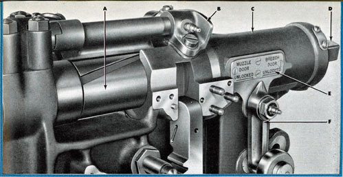
Figure 72 Breech bracket, showing breech and muzzle door interlock lever at breech door unlocked position. (A)
Cylindrical slide; (B) Indicator showing position of muzzle door when opening or closing. (C) Breech bracket;
(D) End of muzzle door operating shaft for attaching handle; (E) Indicator, showing (F) Breech and muzzle door interlock lever at breech door unlocked position, ready for unlocking and opening the breech door.
is shown on the Muzzle Door Indicator (see
Figure 73, also C in Figure 68). This indicator consists of a ring with a pointer on its outer surface or
circumference, and, a tooth immediately below it
on the inner surface of the ring. The tooth engages
a helical groove in the slide, so that as the slide
moves backward or forward the indicator moves,
showing the position of the muzzle door on the
scale.
With the power-operated mechanism, the shaft
for opening and closing the muzzle door is operated by a hydraulic cylinder which, in turn, is
operated by a control valve, the control valve being
set in action by a thrust rod which moves through
the interlock sleeve and the breech bracket. This control valve cannot be set in action unless the interlocks
are in proper position.
Rods extend down from the breech and muzzle
door interlock lever and from the drain valve and
muzzle door interlock lever, and connect with gearing which locks or unlocks the emergency hand
operating shaft (H in Figure 45, page 32). The
interlock slide is moved backward or forward by
an interlock chain.
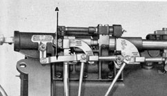
Figure 74 New connecting rod (A) Linking the breech and muzzle door interlock lever with the drain valve and
muzzle door interlock lever so the two operate together. Levers as shown are at muzzle door locked, and breech door
unlocked, positions. At right, Figure 75, levers are shown at muzzle door unlocked, and drain valve locked, positions.
41
TUBE DRAIN VALVE AND MUZZLE DOOR INTERLOCKING MECHANISM
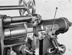
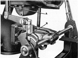
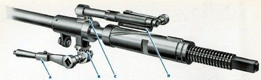
Figure 76 Drain valve interlock, showing (A) Rod extending up to interlock lever and cylindrical slide; (B)
Collar on drain valve shaft disengaged, valve unlocked.
The interlocking mechanism also provides an
interlock between the tube drain valve and the
muzzle door, so that the muzzle door can not be
opened unless the tube drain valve is closed.
The tube drain valve, located just under the
breech end of the tube, is operated by a lever attached to a shaft, at one end of which is a collar
(B in Figure 76). This collar is locked or unlocked
by moving the drain valve and muzzle door interlock lever (A in Figure 77). The interlock lever
has a pinion gear which engages a rack gear (B in
Figure 77) attached to a rod (A in Figure 76)
which extends down to a lever which operates an
interlock bolt which operates on the collar on the
drain valve stem (B in Figure 76). This rod also
extends up to the cylindrical slide, as shown at
C in Figure 77.
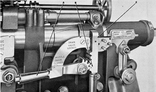
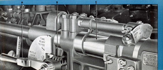
Figure 77 Drain valve and muzzle door interlock, showing (A) Lever at muzzle door closed position; (B) Pinion
gear and rack with (C) Head of rod in upper position, engaging slot in cylindrical slide.
42
When the interlock lever is at "Muzzle Door
Closed" position, the head of the rod engages the
slot in the cylindrical slide (C in Figure 77) so
the muzzle door operating shaft can not be moved.
The collar on the drain valve stem is disengaged,
as shown at B in Figure 76, and the drain valve
lever may be moved to open the drain valve.
The collar on the drain valve shaft is locked,
as shown at B in Figure 78, when the interlock
lever is moved to "Drain Valve Locked" position,
thus preventing movement of the drain valve lever,
and the head of the rod disengages the cylindrical
slide, as shown in Figure 79, permitting movement
of the muzzle door operating shaft so as to open
the muzzle door.
This interlock acts in the same manner on tubes
which have power-operated muzzle door mechanism.
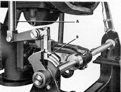
Figure 78 Drain valve shaft, showing (A) Rod in
lower position, engaging (B) Collar on drain valve shaft
and locking valve.
Figure 79 Drain valve interlock, showing (A) Interlock lever at drain valve locked position, with (B) Head of
rod disengaged from slot in slide, releasing muzzle door operating shaft.
43
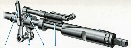
Figure 80 Firing interlock disassembled, showing (A) Lever in muzzle door unlocked position; (B) and (C)
Gearing drive for firing interlock bolt through idler mounted on muzzle door operating shaft; (D) Firing interlock
bolt, shown turned out of the way of interlock slide. (Compare with Figure 82.)
FIRING INTERLOCKING MECHANISM
Firing Interlocking Mechanism prevents firing
the tube until other interlocks are correctly set.
The firing interlock lever rotates the interlock
sleeve (Figure 80). When the lever is at "Muzzle
Door Unlocked" (Figure 81) the interlocks on the
depth and speed setting mechanisms are released
so the spindles can be moved in to engage the
mechanisms in the torpedo. When the depth and
speed setting mechanisms are engaged with the
torpedo, hubs on the interlock sleeve prevent rotation of the interlock sleeve head by the firing interlock lever.
When the firing interlock lever is moved to
"Tube Ready to Fire" (Figures 82 and 83), after
the spindles of the setting mechanisms have been
disengaged from the torpedo, the tube firing system is released ready for firing.
Raising the firing interlock lever from "Muzzle
Door Unlocked" to "Tube Ready to Fire" also
rotates the sleeve head which moves the shutter
bar so the opening in the shutter bar is lined up
to allow the piston of the torpedo stop cylinder to
pass through it and set the firing mechanism in
Figure 81 Firing interlocking mechanism, showing (A)
Lever in muzzle door unlocked position, and (B) Pinion
and gear attached to interlock sleeve through which muzzle door operating shaft passes; (C) Position of cylindrical slide. (Also see Figures 80, 82 and 83.)
44
Figure 82 Firing interlock disassembled, showing (A) Lever in tube ready to fire position; (B) and (C) Gearing
drive for firing interlock bolt through idler mounted on muzzle door operating shaft; (D) Firing interlock bolt, shown
turned so as to prevent interlock slide from moving toward muzzle.
operation after the firing key is pressed. The shutter
bar (J in Figure 96 or N in Figure 99, on pages 52
and 53), in addition to the hole intended for the
passage of the stop piston extension, has a recess
which registers with the end of the stop piston
extension when the firing interlock is set for
"Muzzle Door Unlocked." The purpose of this
recess is to engage the end of the stop piston extension if it should be forced breechward as by reason
of the leakage of air under pressure into the stop
cylinder. In such case, the end of the stop piston
extension locks the shutter bar, so the firing interlock cannot be thrown to "Tube Ready to Fire"
position. (If it could be so thrown while there was
pressure in the stop cylinder, the tube would fire
immediately.) At the same time, the electric interlock switch (not adequately shown on any illustration, but actuated by movement of the shutter bar)
is closed, lighting interlock indicator lights.
At the same time, the firing interlock bolt has
been rotated downward, engaging the muzzle door
end of the interlock slide (Figure 83), thereby locking the muzzle door in its open position.
Figure 83 Firing interlocking mechanism, showing (A) Lever in tube ready to fire position; (B) Pinion and gear
attached to the interlock sleeve; (C) Cylindrical slide
locked to prevent movement of muzzle door operating
shaft. (Compare with Figure 81.)
45
INTERLOCK DISCONNECT
Provision is made for disconnecting the firing
interlocking mechanism in order to permit of testing the operation of the firing mechanism. This
test consists of firing what is called an "inboard
slug," or a charge of air, while the breech door
is open.
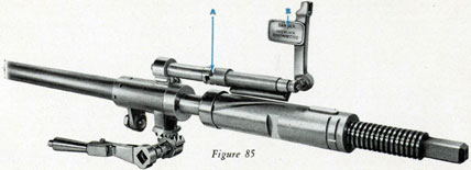
To make this test, the lock on the interlock disconnect (see Figure 84) is unlocked and removed,
the interlock signal arm is raised to vertical position,
showing the "Danger, Interlock Disconnected"
warning flag (see B in Figure 85), also disengaging
the firing interlock clutch shaft (see A in Figure 85)
and permitting the stop and firing mechanism to
function, regardless of the position of the breech
door or the drain valve interlock levers, for the
purpose of testing the firing mechanism.
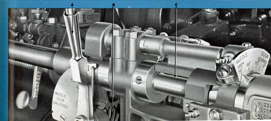
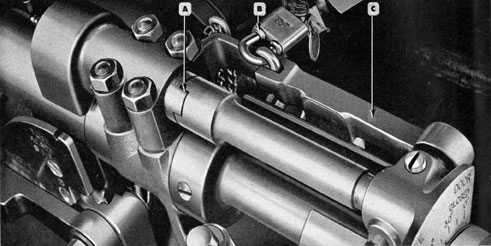
Figure 84 Firing interlock disconnect, showing (A) Clutch shaft engaged; (B) Lock which must be removed to
disconnect interlocking mechanism; (C) Interlock signal arm. Compare with Figure 85, below, showing the cylindrical
slide disassembled, with (A) Clutch shaft disengaged, and (B) Interlock signal arm raised to show warning flag.