Maintaining, in good working order, mechanisms
such as those described in this pamphlet, depends
entirely upon the skill and zeal of the operating
personnel, and upon their detailed and thorough
understanding of the construction and function of
each unit in the mechanism. In view of the number
of parts involved, it is considered impracticable
to foresee and instruct against every malfunction or
casualty which will be encountered in service. Also,
in view of the varying conditions which will be
met with in service, it is considered impracticable
to establish lubrication or maintenance routines. In
general, circumstances permitting, each working
part of a submarine torpedo tube should be exercised
daily, under war conditions, and lubrication
and other maintenance performed as the necessity
is indicated by the exercising.
The purpose in this chapter is to present certain
principles that are generally applicable, and to direct
attention to a few specific cases where trouble may
be anticipated, based wholly upon service experience
up to this time.
2. LUBRICATION
All working parts should be maintained in a clean
and oily condition. Lubrication charts are included
in the General Information Books supplied each
vessel by the Bureau of Ships, and these should be
referred to for complete information regarding the
lubrication on each particular vessel. In the absence
of other instructions, the inside of the barrel should
be dried occasionally, and coated with a heavy mineral
oil, such as 60O W (or Navy symbol 6135).
Caution: Oil electrical parts sparingly, if at all,
using a very light mineral oil. Also, care must be
exercised in the choice of general lubricants, since
some commercial lubricants which are reasonably
satisfactory for steel will corrode bronze, especially
in the presence of salt and moisture. Old lubricant
should be wiped off as much as practicable before
renewing the application, since some oils, in the
presence of salt and moisture, tend to thicken and
harden, turning dark-colored in the process, and
definitely losing their lubricating properties.
3. WEAR OR DEFORMATION
All working parts should be scrutinized at every
opportunity, to detect and remedy any incipient
causes of failure. For example: Tripping latch linkages, stop rods, and interlocks should be examined
for deformation and lost motion, and for correspondence between actuation and response, to make
certain, for instance, that when the tripping latch
is raised by opening the breech door, it does not
project within the 21.125 inch bore of the tube,
which would cause the tripping latch to interfere
with the loading of a mine; also that when it is
lowered, with all lost motion taken out in the up
direction, it projects within the bore by only the
required amount as shown on the drawings which
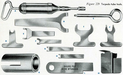
are applicable to the specific vessel. The gage supplied in the tool kit (M in Figure 229) may be used
for this purpose.
Also, when a stop bolt is down, and with all lost
motion taken out in the up direction, its lower face
should be at the height prescribed by the applicable
drawings and as checked, if practicable, by the
barrel center line gage.
4. ADJUSTMENTS
Before undertaking to adjust any mechanism on
a torpedo tube, reference should be made to the
applicable drawings. The chances are that if one
mechanism is adjusted differently than shown on
the drawings, possibly in an effort to improve its
operation, it will be found that it is rendered unsafe in some other respect, or that the operation
of some other related mechanism has been impaired.
Where this appears to be definitely not so, the
Bureau of Ordnance should be notified at the
earliest practicable date to facilitate appropriate
decision and action.
5. STUFFING BOXES
The stuffing boxes should not be tightened more
than just enough to prevent leakage. From the
136
operating standpoint, it is even sometimes better
to accept a slight leak until the box can be properly
repacked, than to take up on the stuffing box so
much that it will bind a working part. This is
particularly true with respect to the stop rod, since
the result of a sluggish firing movement, which
could be caused by improper action of the stop rod,
will, under some conditions of adjustment, be an
excessive tube pressure. It is considered good practice to keep the stuffing box friction upon the stop
rod down so that the rod will move freely with the
ship's service air at one-half of its normal pressure.
6. PRESSURE GAGES
Pressure gages are particularly subject to derangement, especially when subjected to vibration or
shock. They should be calibrated regularly at reasonable intervals, and whenever their accuracy is in
question for any reason, or after being subjected
to unusually strenuous treatment. Under conditions
of active service, it is considered that they should,
if practicable, be calibrated after each war patrol.
It is usually practicable to check a gage by comparing its reading with that of another gage in the
same line. Where this is so, such comparison should
be made during all drill or exercise periods.
7. GASKETS
Gaskets tend to deteriorate when held under pressure, and also when subjected to excessive temperature changes, or when exposed to moisture or oil,
especially so if they contain natural rubber or some
Figure 229 Torpedo tube tools.
A
Grease gun, for use on all fittings
B
Spanner for muzzle door mechanism coupling, and interlock mechanism
C
Firing valve lifter
D
Spanner for gyro spindle retracting mechanism
E
Spanner for depth setting and speed setting mechanism
F
Spanner for use with depth setting mechanism and poppet valve operating mechanism
G
Spanner for speed setting and depth setting mechanisms
H
Spanner for packing nut on depth setting mechanism
I
Spanner for speed setting mechanism
J
Spanner for gyro setting mechanism
K
Mine stowage adapter
L
Gage for mine stowage
M
Gage for testing projection of tripping latch inside of tube
137
of the usual substitutes. The gaskets should be
replaced whenever they appear to have become
permanently deformed, checked, hardened, or sticky.
8. VALVES
Valves should be exercised, particularly those not
used in normal operations. This applies with particular force to the manually operated valves which
close off the poppet valve discharge. Although no
occasion may arise for the use of this valve during
the life of a particular vessel, it is the ultimate safety
feature in the operation of poppet valves, and should
be maintained accordingly.
9. AUTOMATIC DRAIN VALVE
This valve, which will be found at the bottom of
the firing and check valve body, as described on
page 60, in Chapter 5, on the firing mechanism,
should be exercised occasionally by hand to make
certain that it is not sticking.
10. SOLENOID ACTUATED
FIRING VALVE
The stop cylinder valve, described in Chapter 5,
on page 51, should be exercised occasionally by
hand, making certain that the interlock bar is not
in the ready to fire position. At the same time, the
cleanliness and operating condition of the solenoid
and the firing lever should be observed, particularly
since the operation of poppet valves greatly increases
the likelihood of corrosion of all parts of the tube
nests.
Make certain, also, that the vent holes in the
stop cylinder, and in the stop cylinder head, are
clear. If the former are obstructed, the firing action
will be sluggish. If the latter are not clear, and the
solenoid actuated valve leaks, air pressure will build
up in the stop cylinder, causing the end of the stop
rod to engage with the interlocking bar so that it
can not be moved to the ready to fire position.
11. THE PILOT VALVE
The pilot valve, which is at the end of the stop
cylinder, as described in Chapter 5, on page 52,
vents the air chamber above the firing valve,
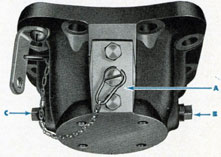
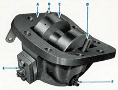
Figure 230 One type of barrel roller bracket. (A)
Heating cable stuffing box; (B) and (C) pipe plugs
in openings for drains.
permitting the firing valve to open so as to fire a
torpedo. If properly seated, the pilot valve is best
left alone, except during overhauls. Leakage of this
valve may cause the firing valve to flutter on its
seat, or possibly even to open entirely. If any water
used to prime the firing valve is blown over by
firing, that fact should be evident, after firing, by
an examination of the pocket in the stop piston
housing into which this pilot valve vents.
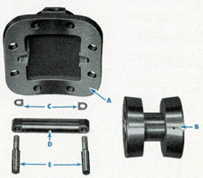
Figure 233 Roller parts disassembled.
(A) Bracket; (B) Roller; (C) Shims; (D)
Roller pin; (E) Screws for roller pin.
138
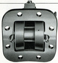
Figure 231 View of barrel roller assembled in bracket.
12. BARREL ROLLERS
There are four rollers fitted on the under side
of the tube, these rollers supporting the torpedo
while it is in the tube. These rollers facilitate the
movement of the torpedo as it passes through the
tube, and case the effort of loading. In addition,
they furnish a means whereby the position of the
torpedo in the tube may be adjusted very slightly.
In general, they should be set to project about
.03 inch within the tube. When the rollers are in
Figure 232 Barrel roller, assembled in bracket, showing (A) Bracket, flange for attaching to barrel; (B)
and (D) Screws for roller pins; (C) Roller; (E) Heating cable stuffing box; (F) Pipe plug in opening for
drain.
this position, the torpedo should be approximately
centered in the tube, there should be no binding or
scraping during the loading, of a torpedo, and the
depth, gyro, and speed setting spindles should engage and disengage in the sockets of the torpedo
readily.
Adjustment of the rollers is obtained by shimming
under the ends of the roller axle pin in each roller
bracket. When removing any roller, note should be
made of the thickness of the shims under each end
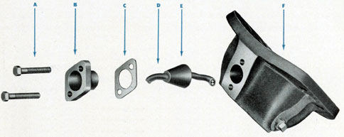
Figure 234 Parts of heat adapter for roller bracket, disassembled.
(A) Bolts; (B) Stuffing Box; (C) Gasket; (D) Heater Cable; (E)
Rubber packing; (F) Roller bracket.
139
of its axle pin, and this should not be changed
except after experiment with an actual torpedo
while the vessel is water borne. During each over
haul period, and between such periods when the
desirability is indicated by inspection, each roller
should be removed and its bore and axle pin cleaned.
The roller pocket nearest the breech of each tube
is fitted for the entry of an electrical heating cable.
Several different types of such fittings have been installed.
The type now regarded as standard is shown
on Figure 234. An earlier type is indicated on Figures 230, 231 and 232.
13. TAIL STOP
The tail stop provides a means for holding the
torpedo against the stop bolt in order to prevent
any motion of the torpedo that might otherwise
occur due to inclinations, sudden shock, and so on.
If the stop plate has been fitted with a rubber pad
or gasket to beat against the propeller nut of a
torpedo, the tail stop should be screwed home quite
firmly, since one purpose of the rubber gasket is
to minimize the surging of water into and out of
the tail cone of a torpedo such as may occur in an
upper tube while running on the surface with
muzzle doors open.
If the stop plate has not been fitted with the
rubber pad or gasket, the tail stop should be screwed
up hard and then backed off about one-eighth of a
turn, as described on page 27 (see Figures 31 and
32), so as to avoid putting a load on the stop bolt
which might cause sluggish action.
In order to use a torpedo tube testing set, as
described in the preceding chapter, in the section
covering test procedures, it is necessary, if a rubber
pad is installed on the stop plate, to remove all metal
parts which secure the pad, that is, referring to
Figure 31, the long securing stud with its outer nut
(standard form) and its inner nut (conical) and the
brass washer under the conical nut. If the rubber pad
adheres tightly to the stop plate where it has been
cemented, it may be left in place. If not, remove it.
If no rubber pad is fitted, the three-eighths inch iron
pipe size plug which in that case closes the hole in
the hollow stop spindle must be removed. In either
case, after using the test set, return all parts to their
original position. If, for any reason, the torpedo cannot be normally clamped between the stop bolt and
the tail stop while the testing set is installed, do not
engage depth, speed or gyro setting spindles, since if
the torpedo moves more than a few hundredths of
an inch, it will bend the spindles, if engaged.
14. FIRING VALVE
Proper ejection of a torpedo is dependent upon
the attainment of a proper tube pressure, which
should be neither too high nor too low, and this,
in turn, depends entirely upon the automatic operation of the firing valve. The rate of opening of the
firing valve is regulated by the throttled flow of a
definite quantity of water, the quantity of water
which is contained within the cupped portion of
the valve below the skirt of the upper head the
throttling orifice being the small circumferential
clearance between the outside diameter of the valve
plate and the inside diameter of the skirt of the
upper head (see Figure 104, page 55). The following conditions would cause the valve to fail to lift
so as to properly regulate the tube pressure:
(a) Improper diameter of the outside of the valve
plate or the inside of the upper head skirt. If the
throttling area is too small, the valve will lift sluggishly and the tube pressure will be too low for
proper ejection of the torpedo. If it is too large, the
valve will lift too quickly and the maximum tube
pressure will be too high.
The clearance between the outside diameter of
the valve plate and the inside diameter of the upper
head skirt is very critical. At the most, it amounts
to only a few thousandths of an inch. Once established, it should not be altered. When it is necessary to remove corrosion from either part, it should,
preferably, be chucked in a lathe, rotated at slow
speed, and a very fine abrasive applied cautiously,
as by a polishing cloth. It should be remembered
that, although a slow and painstaking procedure is
onerous, if this clearance once becomes too great
the only remedy lies in replacing one or both of
the parts, followed by a complete calibration check
by the trial firing of torpedoes or dummies.
An operating check of the valve may be made
140
by noting the maximum tube pressure on the gage
fitted for that purpose at the breech.
(b) By the use of a gasket between the valve
body and the upper head which is not of uniform
thickness or hardness, or by failing to screw down
the upper head bolts uniformly, the upper head can
be "cocked" so as to bind the valve and prevent
it from opening properly, resulting in a tube pressure that is too low.
(c) The presence of an air bubble in the space
within the valve and below the upper head skirt,
which is supposed to be filled with water, will cause
the valve to start opening too rapidly, and this will
result in the tube pressure building up suddenly to
a pressure greater than desirable. If the valve has
been properly primed, such a bubble could not exist
except by reason of the failure of some of the air
initially present under the skirt of the upper head,
within the valve, to rise out of that chamber at the
time of filling. Due to the narrowness of the opening, this could be caused by the presence of grease
or other foreign matter around the edge of the
valve plate. The proper method of exercising a firing
valve so as to insure the absence of an air bubble,
and so as to detect any binding which might exist,
is described in the special note following paragraph 3 (b) (5) of the section on Operating and
Test Procedures, Chapter 11, on page 126.
15. DRAIN GRIDS
Drain grids should be kept clear. If zincs are fitted
in any of the drain pockets, they should be renewed
immediately as they become expended.
16. BREECH DOOR LOCKING RING
The breech door locking ring should turn freely
upon its threads on the breech door flange at the
breech end of the barrel. These threads should be
kept clean and oily. The use of abrasives should
be avoided, if possible, and if used it should be
made certain that no abrasive particles are allowed
to remain on the parts. Before disassembling the
locking ring from the flange, a mark should be
made on the ring and the flange at the point where
they disengage, since the threads are triple and will
go together in three different positions.
17. MUZZLE DOOR GASKET
From its location, the muzzle door section "of the
tube is one of the most inaccessible parts for inspection. Therefore, advantage should be taken of
every drydocking to inspect the gaskets, and they
should be replaced on the grounds of less deterioration than that necessary to warrant the replacement
of other similar, but more accessible, parts.
18. SPRINGS
All springs are subject to deterioration in service.
Steel springs are likely to corrode, in spite of any
plating or other preventive measures, and a small
or local decrease in diameter will considerably reduce the load carrying capacity at a given length,
since the deflection under a given load varies inversely as the fourth power of the wire diameter.
On the other hand, springs made of most nonferrous metals have a tendency to take a permanent set when under load, as most springs are.
In consequence, springs should be calibrated during
overhauls whenever facilities permit, particularly
if they are corroded, to see if the requirements as
to loads and deflections shown on the detail drawings in each case are being met, and, if badly corroded or evidently incapable of accomplishing their
intended purpose, they should be replaced without
waiting for a calibration. If springs are replaced,
they should be retained and calibrated later, if practicable, so that they may be available as spares if
still serviceable.
19. ELECTRICAL INTERLOCK
The electrical interlock consists of a snap switch
in series with the firing key. It is closed by the
throwing of the interlock lever to the "Tube Ready
to Fire" position, and is allowed to open, under the
impulse of a spring, when the lever is moved from
that position. It should be exercised occasionally in
order to make certain that it is not sticking in the
"closed" position.
20. ELECTRICAL CIRCUITS
Keep electrical circuits clean, dry, and free from
oil, except that metallic moving parts may be lubricated sparingly on other than contact surfaces. Oil,
141
grease, gasoline, and similar materials, cause rubber
to deteriorate rapidly, and although not so harmful
to synthetic rubbers or rubber substitutes, they are
best kept clear of electrical insulation and similar
parts. All contact surfaces should be kept bright,
unless silver coated. The normal corrosion products
of silver are good electrical conductors.
21. DRAINAGE SYSTEM
Metal to metal valve seats in the drainage system
require only ordinary care beyond an occasional
lapping, should leaks develop. Where valves seat
on rubber gaskets, these should be inspected at each
overhaul, and the gaskets should be replaced when
marred or deteriorated.
The stuffing boxes on the drain and vent valves
should be tight, and the packing in them should
be replaced as necessary, using the packing specified on the applicable drawings, or that called for
by the instructions of the Bureau of Ships.
The tube drain valve, which leads directly to the
drain in the barrel, has on its stem an interlocking
collar so placed so that when the muzzle door is
unlocked the valve can not be opened (see Figures
76 and 78 on pages 42 and 43). Certain mechanical
clearances are necessary, however, and these, cumulatively, plus the effect of wear, make it necessary
that the drain valve operating lever be always given
a full throw in each direction. Also, when necessitated by wear or deformation, parts should be readjusted or replaced to make certain that the interlock
engages and disengages at the proper points.
22. TORPEDO STOP MECHANISM
Avoid any bending of the stop bolt and consequent binding of the parts of the torpedo stop mechanism. Careless loading of the torpedo into the barrel is the usual cause, and particular care should be
taken to bring the torpedo against the stop bolt
gently. A bent or otherwise mutilated stop bolt
should be replaced promptly. The stop rod spring,
and the stop bolt spring mounted in the recess in
the top of the stop bolt, should exert the designed
pressure on the stop rod and the stop bolt, respectively,
and the stop bolt should slide freely in its
housing, as described in Chapter 8 (see page 109).
The adjustment of the stop bolt, the stop rod,
and the connecting levers, should be such that when
the stop bolt is in the fully down position, and the
stop piston and stop rod are at the extreme limit of
travel toward the muzzle end of the tube, the clearance between the rounded end of the stop bolt lever
and the bottom of the slot in the stop bolt will be
approximately 0.025 inch. This clearance should not
be allowed to exceed 0.06 inch.
The clearance between the rounded end of the
stop bolt lever and the top of the slot in the stop
bolt should be approximately five-sixteenths of an
inch. This comparatively large clearance is provided
in order to prevent accidental release of the torpedo
by lifting of the stop bolt if an attempt is made to
fire the tube, or if pressure should leak from the
ship's service line and build up in the stop cylinder,
while the interlocking shutter is in the "safe" position, blocking the travel of the stop rod, the amount
of travel permitted the stop rod under these conditions being insufficient to take up the clearance
mentioned.
Before loading a torpedo into the tube, sight
through the barrel to see that the stop bolt projects
into the guide slot of the tube the full distance.
When fully down, the lower end of the stop bolt
should be flush with the bore of the tube. Failure of
the stop bolt to occupy its proper position when the
torpedo is loaded will permit the torpedo to move
too far forward in the tube, tripping the starting
lever, and probably striking and damaging the
muzzle door.
A threaded adjustment is provided between the
gyro setting retraction slide and the stop connecting
rod (see Figure 212, page 114). By means of this
adjustment, the "free lift" of the stop bolt may be
held within the limit of 0.06 inch specified above.
It sometimes happens that the stuffing box gland is
taken up so tightly as to prevent the stop rod from
making its stroke properly. Look for this after
tests of compartments. The stop rod should make its
stroke with a pressure of 100 pounds per square
inch on the ship's service line, the normal pressure
being 200 pounds per square inch.
142
23. SETTING SPINDLES
"DO NOT OPEN THE BREECH DOOR of the
tube without first making sure that the depth, speed
and gyro setting spindles are withdrawn. These
spindles are designed to take only the torque which
is necessary to make the settings in the torpedo. In
addition, they are mounted so as to have a certain
amount of freedom in all directions, so that they will
engage the sockets of a torpedo even though these
sockets do not line up exactly with the tube units.
Hence the spindles cannot be relied upon to retain a
torpedo in place in a torpedo tube, and if they are
engaged while the breech door is open and the torpedo is given any perceptible impulse to the rear,
they will only be bent, without noticeably preventing movement of the torpedo."
24. POWER-OPERATED
MUZZLE DOORS
It will be observed that operating the door by
hand is certain to put the jack nut "out of step"
for power operation, and that it is necessary, after
operating the muzzle door by hand and before
reverting to power operation to:
(1) Make certain that the door is either tightly
closed or is open as wide as it will go, and
(2) Rotate the hand crank until the jack nut
matches with the proper one of the two projections D on Figure 64, that is, with the breech
ward projection if the door is closed or with the
muzzleward projection if the door is open.
As this pamphlet goes to press, there has been
authorized an additional interlock (for new construction) consisting of a bolt which is thrown by a
linkage from the firing interlock lever (see Plate 3).
This bolt, when the door is fully open, will pass to
the rear of the muzzle door operating shaft (permitting the firing interlock lever to be placed in
the tube ready to fire position). When so placed,
the bolt will (up to the limit of its strength) prevent the closing of the muzzle door.
Where this last interlock has not been installed,
there is a possibility that the muzzle door will not
remain fully open in the event of the failure of
hydraulic power after the door has been opened
by power. To prevent such partial closing of the
door, it is only necessary to go through the motions
of opening the door by hand. This will bring the
jack nut on the operating shaft against the after
projection of the operating shaft bracket, where
it will act as a stop collar.
143
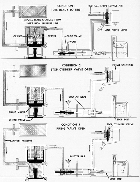
Torpedo tube firing schematics.
The three schematic diagrams above explain the
operation of the tube firing system, described
on pages 48 to 60 (see, especially, page 49).
144
DISTRIBUTION
Requests for additional copies of O.P. 1085 should
be directed to the nearest BuOrd Publications Distribution Center: Navy Yard, Washington, D. C.;
Mare Island, California; Adak, Alaska; Pearl Harbor,
Hawaii; Espiritu Santo, New Hebrides; Exeter,
England; Brisbane, Australia. Distribution Center
mailing addresses should be obtained from list 10 nn
on the Standard Navy, Distribution List.
DISTRIBUTION
Standard Navy Distribution List No. 21; 2 copies
each unless otherwise noted.