3A1. General. In submarines as in all ships,
a certain amount of water from various
sources accumulates inside the hull. The most
important of these sources include:
1. Leakage at-glands around the propeller
shafts, pitometer log, sound gear, periscopes,
and similar equipment.
2. Draining of air flasks, manifold drain
pans, conning tower deck, gun access trunk,
and escape trunk.
3. Condensation from air-conditioning
cooling coils.
This water drains off into the bilges and
wells where a number of bilge sumps with
strainers are provided from which the bilge
water can be pumped.
The bilge sumps and wells are pumped
periodically to prevent the excess free water
from overflowing the bilges and interfering
with the operation of the submarine. This
water is pumped out by the drain system
which consists essentially of the drain pump
and the piping connecting the pump with the
sumps and other drainage points in the submarine. Reference to the general arrangement
shown in Figure 3-9 will be helpful in understanding the functional description which follows.
3A2. Functional description. The drain pump,
located in the pump room, provides suction
for the drain system. The pump is started and
stopped by means of an electric push-button
switch located nearby in the pump room. The
drain pump has a suction and a discharge connection. A suction line equipped with a
strainer and a sight glass connects the suction
side of the pump with the main forward and
after drain lines, usually called the drain line
forward and the drain line aft. The drain line
forward and the drain line aft can be cut off
by shutting their respective stop valves, located in the pump room.
In Figure 3-9, proceeding forward from
the pump room, it an be seen that the drain
line forward extends to the forward torpedo
room and provides pumping connections for
the two bilges and the pitometer log well in
the after section of the torpedo room. The
drain line terminates at the forward bilge
manifold, with two valves controlling the suction from the poppet valve drain tank and
the forward bilge.
The escape trunk drain opens into the
forward torpedo room; the water drains directly onto the deck and eventually empties
into the bilges.
There are no drain line connections in the
forward battery compartment.
The drain line aft extends to the after
torpedo room and contains pumping connections to the sumps in the compartments in the
after section of the submarine. There are no
drain line connections in the after battery
compartment. The forward engine room has
two bilge sumps connecting with the drain
line aft through two individual lines. The
after engine room also has two bilge sumps
which connect to the drain line by means of
two separate lines. In addition to the bilge
sump pumping connections, the drain line aft
contains also a suction line to the collecting
tank, making it possible for water from the
collecting tank to be pumped out through the
drain system.
There is one bilge sump in the motor
room.
The drain line aft terminates in the after
bilge manifold in the after torpedo room.
Here too, the manifold contains two valves,
controlling suction from the forward and
after bilge sumps.
Returning now to the pump room, the
drain pump suction line carries a branch connection to the pump room bilge manifold.
This manifold contains three valves controlling suction from the three pump room bilge
sumps.
20
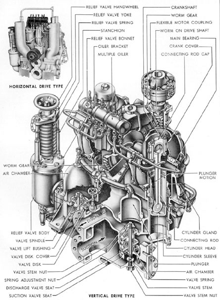
Figure 3-1. Drain pump.
21
The drain water from the gun access
trunk, the cable trunk, the periscopes, and the
antenna wells empties into the pump room
bilge and collects in the sumps from which
it is pumped when required.
The drain pump has three points to
which it may discharge: 1) the overboard discharge; 2) the compensating water main; and
3) the trim system. In addition, the drain
pump is so interconnected with the trim manifold that it can discharge water into the trim
system instead of into its own piping. This
interconnection permits the use of either the
drain pump or the trim pump with either the
trim or the drain system, in the event that one
of the two pumps is not in operating condition.
Every branch suction line to the bilge
sumps has its own bilge stop valve. When it
is desired to pump out certain bilge sumps,
or wells, the valves leading from them to the
drain line and the pump are opened. The required discharge valves are then opened to
the overboard discharge, the compensating
water main, or the trim system, depending
upon the conditions. Then the drain pump is
started and the pumping begins. When the
pumping is completed, the pump is stopped,
and the valves to the various lines used in the
operation are shut.
The drain system can discharge the bilge
water directly overboard, into the expansion
tank through the compensating water main,
or into the trim system through the trim manifold.
Bilge water should not be discharged directly overboard if there is danger of detection by the enemy, because the oil in it will
rise to the surface, indicating the presence of
the submarine. Instead, bilge water should be
pumped into the expansion tank, where the
water separates from the oil before being discharged overboard.
If the trim system is used to receive the
bilge drainage, it is possible to pump this
water into the variable ballast tanks. But this
may be a hazard to security, because discharging variable tanks to sea during trimming
operations will allow bilge oil to rise to the
surface, leaving the telltale oil slick.
B. DRAIN PUMP
3B1. Source of power. An electric motor,
rated at 10 horsepower and 1150 revolutions
per minute, is used to drive the drain pump
through-a worm and worm gear assembly as
shown in Figure 3-1. The two types of pumps
in use are shown in this illustration. One
has a vertically mounted motor and is shown
in the large cutaway view; the other has the
"motor mounted horizontally and is shown in
the upper left-hand corner of Figure 3-1. The
cutaway view shows the mechanical construction of the pump.
3B2. Description. The drain pump is a single
acting duplex reciprocating pump with the
cylinders mounted vertically. The two plungers are connected to the crankshaft by connecting rods, so that one plunger completes
its downward travel at the moment the other
plunger completes its upward travel. As a
plunger moves upward in the cylinder, it
creates vacuum, or suction. This lowered pressure
"draws" water into the cylinder through
the valves from the inlet, or suction, port.
When the plunger reaches the top of its
stroke and starts its downward travel, the
water forces the suction valve down, closing
the inlet port, opening the discharge valve,
and allowing the water to flow out of the discharge port. At the same time, the second
plunger is performing the reverse operation,
taking a suction while the first plunger is discharging. This results in a continuous flow of
water through the pump.
An air chamber is provided for each cylinder to smooth out the flow and quiet the
pump operation by cushioning the discharge.
Air in the chamber is compressed during discharge. When the plunger reaches the end
of its stroke, expansion of this air tends to
keep the water flowing until the reverse stroke
begins.
A connection is provided to the 225-pound
air system for recharging the chambers.
22
Indicator lights show when the chambers need
charging or venting.
3B3. Lubrication. Lubrication of the main
bearings and the connecting rod bearings is
accomplished by the multiple oiler mounted
on the pump casing. Oil reaches the bearings
through holes drilled through the crankshaft
and connecting rods. The worm gear drive
runs in oil which is cooled by sea water circulating through a coil installed in the worm
drive housing.
3B4. Relief Valve. The relief valve, set at
225 pounds per square inch, is mounted on
the pump body and protects the pump from
excess pressure in case a valve is shut on the
discharge line when the pump is operating.
A drain cock is provided to allow the
draining of all water from the pump.
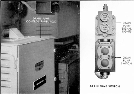
3B5. The drain pump controls. The electrical
controls for the drain pump consist of the
motor switch, the air chamber pressure
indicators, and the control panel. All are
mounted on the port side of the pump room.
The motor switch is equipped with a
push-button for starting, a push-button for
stopping, and a signal light which is ON
when the motor is running.
The drain pump control panel is housed
in a ventilated panel box with a removable
door. This panel supports the contactors,
relays, fuses, and overload relays of the
control circuit.
The air chamber pressure indicator consists of two lights which show the conditions
existing in the pump air chambers. They are
controlled by a limit switch mounted in the
air chamber. If too much water is in the
chambers, both lights will be ON. In this case
air should be blown into the chambers until
one light goes OUT. If both lights are OUT,
insufficient water is in the chambers, and they
must be vented until one light goes ON.
Figure 3-2. Drain pump controls.
23
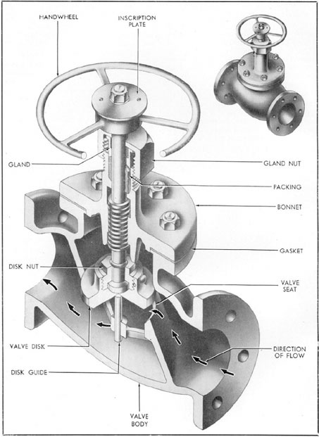
Figure 3-3. Drain line stop valve.
24
C. VALVES AND FITTINGS
3C1. Drain line stop valves. In Section 3A
it was explained that the suction of the drain
pump could be applied to either the forward
or the after drain line. The drain system is
provided with two valves, known as the forward and the after drain line stop valves,
respectively. These valves will put either
drain line on SERVICE, depending on which
section of the boat is to be serviced. These
two valves are located on the port side of the
pump room, forming the connection between
the line leading to the suction side of the
drain pump and the forward and after drain
lines (see Figure 3-9).
The forward drain line stop valve is an
angle valve of the disk and seat type, with
a bolted bonnet, a rising stem, and flanges
for connection to the lines. The after drain
line stop valve is a globe valve, the construction of which is shown in Figure 3-3.
Opening the forward drain line stop
valve by its manually operated handwheel
places the forward drain line on SERVICE
and permits the use of the forward section
of the drain system. Similarly, the after drain
line stop valve is used to place the after drain
line on or off SERVICE.
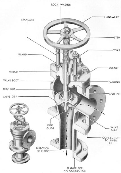
3C2. Drain pump overboard discharge valve.
When the water collected from the bilges by
the drain system is to be discharged directly
to the sea, two valves must be opened to provide a passage for the drain water.
The inboard valve is a stop check valve;
the second valve is outboard of the first and
is known as the drain pump overboard discharge valve (see Figure 3-4). Both are
located on the port side forward in the pump
room, and are mounted in tandem so that the
stop check valve acts as a sea stop for the
discharge valve.
The mechanical details of the drain pump
overboard discharge valve are shown in
Figure 3-4. The valve is mounted with the
outboard leg extending through the pressure
hull; the midway flange is bolted and gasketed
to the hull to insure a pressure-tight connection. The threaded flange is connected to
the pipe leading overboard. The flange on
the inboard leg of the valve is connected to the stop check valve on the line leading to
the drain pump discharge. The bolted bonnet
gives access to the disk and seat valve for
inspection and repair. The adjustable packing gland prevents leakage around the rising
stem when the valve is subjected to depth
pressure.
When discharging from the drain pump
to sea, the manually operated overboard discharge valve must be opened. It is shut immediately after the discharging operation is
completed.
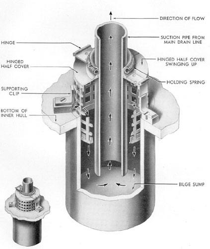
3C3. Bilge strainer. Although the purpose
of the bilges is to collect excess water, solid
material such as flakes of paint and bits of
metal inevitably finds its way into the bilges.
If this solid matter were to enter the lines of
the drain system, it might clog or damage
the drain pump. As a precaution, each bilge
sump is equipped with a bilge strainer
(Figure 3-5) which-screens the bilge water
before it enters the drain system lines, and
holds back any large particles.
The three bilge sumps in the forward
torpedo room, the three in the pump room,
the two in each engine room, the one in the
motor room, and the two in the after torpedo
room are equipped with bilge strainers of the
general type shown in the illustration. The
only exception is the after bilge sump in the
after torpedo room which is equipped with a
Macomb strainer. The size and shape of the
strainers vary somewhat to suit the individual
bilge sumps.
The strainer consists of an open-bottom
mesh cylinder set in the bilge sump. The
mesh is held in place by clips screwed to
chocks which are welded to the pressure hull.
The top cover is split and has hinged sides.
It is held tightly closed around the bilge
suction pipe by a holding spring.
The bilge water enters the strainer
through the screen, which holds back all large
particles of solid material; the water drops
into the well and is sucked into the drain
system through the drain pipe. To remove
foreign matter which may collect in the well,
25
Figure 3-4. Drain pump overboard discharge valve.
26
Figure 3-5. Bilge strainer.
27
Figure 3-6. Malcomb strainer.
28
Figure 3-7. Drain line sight glass.
the hinged covers may be opened by slipping
off the holding spring.
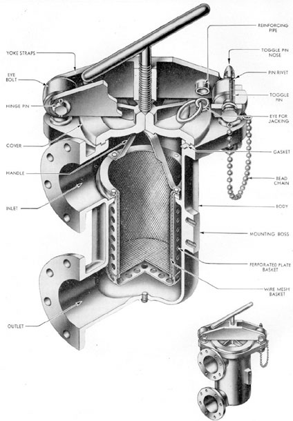
3C4. Macomb strainer. Although the bilge
strainers will prevent pieces of solid material
larger than a half-inch from entering the
drain system, it is necessary to screen the
water again to remove any smaller particles
of debris that might clog or damage the drain
pump. Such material is filtered out of the
drain system by the Macomb strainers.
Figure 3-6 illustrates the construction of
a typical Macomb strainer. The shape of the
body and the position of the inlet and outlet
ports vary somewhat in individual cases to
suit conditions of space or use.
The strainer is connected into the drain
suction line in such a manner that bilge water
flowing therein will enter the inlet port and
pass through the wire mesh basket before
leaving by the outlet port to continue on to
the drain pump.
The wire mesh basket permits water to
flow freely from inlet to outlet but traps and
retains all solid matter larger than the holes
in the wire mesh. The perforated plate basket
serves to support and protect the wire mesh
basket to which it is attached. The entire
basket assembly can be removed for cleaning.
The basket handle is used both for lifting
and for holding the basket securely in place
against the shoulder inside the body.
To clean the strainer, it is necessary to
loosen the handle bolt, withdraw the self-locking toggle pin, and swing back the hinged
yoke. The cover can then be lifted off using
the ring provided, and the basket lifted out
and cleaned. The reverse procedure is used
in replacing and closing the strainer. After
the yoke has been secured, the handle bolt
is screwed down tightly to provide a leak-proof fit between the body and the cover. A
plug is provided at the bottom of the body
for draining.
29
Figure 3-8. Pitometer log well suction line and sump.
30
There are three Macomb strainers in the
drain system: one is connected into the drain
pump suction line in the pump room; an
other is connected into the collecting tank
drain line in the after engine room; and the
third is in the after torpedo room on the drain
line running from the bilge to the after bilge
manifold.
A fourth Macomb strainer is used in the
trim system. It is located on the trim pump
suction line in the pump room and is used to
protect the trim pump from debris in the
water ballast.
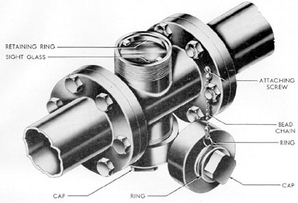
3C5. Drain line sight glass. The drain line
sight glass (Figure 3-7) provides a means of
determining visually the amount of oil or
solid matter in the bilge water as it flows
through the lines of the drain system. It consists of a cross-shaped casting, two ends of
which are flanged and connected to the drain
lines. The other arms are fitted with glass
plates to allow inspection of the water in the
drain line.
The glass windows are protected by caps
which screw onto the body of the fitting,
protecting the glass from damage. The covers
are attached to the fitting by bead chains
and are provided with squared heads to fit
the wrench used in removing them.
In use the cap is removed and the fluid
in the drain line is visible through the sight
glass. If more light is needed, the cap on the
other side of the drain line may be removed
and an external light flashed through the
fluid in the line to the sight side.
There are two drain line sight glasses,
one on the suction line near the drain pump
strainer in the pump room, and the other in
the after engine room on the collecting tank
drain line.
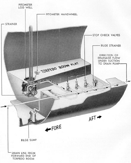
3C6. Pitometer log well suction line and
sump. The water which collects in the
pitometer log well is pumped out by the
pitometer log well suction line. This line extends from the main drain line and runs
athwartship along the after bulkhead of the
forward torpedo room to the pitometer log
well.
It is equipped with a bilge strainer which
is fitted into the well. A stop check valve
mounted in the line between the well and
the forward drain line (see Figure 3-8), is
opened to pump the pitometer log well.