CARE AND MAINTENANCE
OF THE MODEL X-1 DISTILLING UNIT
A. REPAIRS
9A1. Evaporator. Repairs to the shell sections
and the head of the evaporator can be made only
at locations where careful preheating can be done
before brazing, and where facilities for annealing
the entire section at about 750 degrees F. after brazing
are available. Small cracks in a seam however,
may be repaired by carefully heating and then
covering the crack with soft solder.
Leaky tubes may be rolled with the expanders
provided in the spare parts box, or the tubes may
be driven out and replaced in the usual manner.
9A2. Heat exchanger. The heat exchanger is of
special type construction with the tubes made
tight by packing rings. The packing rings are of
both metallic and fiber construction and the exchanger may leak a little if it has been standing
a long time without use or if it has just been repaired with new packing. When this occurs the
exchanger tubes should be filled with water and
allowed to stand for 3 or 4 hours during which
time the fiber material will swell and the exchanger will then be tight under test. The exchanger should not leak in service since the packing
will always be wet.
9A3. Procedure for packing exchanger. The packing for the exchanger is shipped in packages, each
package containing 120 each of the fiber and metallic rings for the 1 1/4-inch i.d. tubes and 120 each
of the fiber and metallic rings for the 3/4-inch
o.d. finned or wired tubes. Always use a fiber
ring first and a metallic ring second when packing
3/4-inch tubes, and a metallic ring first and a
fiber ring second when packing 1 1/4-inch tubes.
Packing tools will be found in the spare parts
boxes.
It will normally never be necessary to replace
the 1 1/4-inch tubes, but should this have to be
done, all the 3/4-inch tubes must be driven out
and the plates removed before work may be done
on the 1 1/4-inch tubes. The 3/4-inch tubes are
easily removed so that the 1 1/4-inch tubes may be
exposed in a relatively short period of time. Care
should be taken in selecting the proper size metallic and fiber packing for each tube because the sizes
are only slightly different.
To repack the 3/4-inch tubes proceed as follows:
a. Remove the nuts and covers from both ends
of the exchanger.
b. Place the pipe sleeves over the studs and replace the nuts to hold the plates together.
c. Secure the guide pin tool for the 3/4-inch
wired or finned tubes from the spare parts box.
This is piece No. 811-1c:
d. Insert the guide pin tool in the 3/4-inch tube
and drive the tube just through the plate, using the
wooden mallet.
e. Drive out the 3/4-inch tubes which need repacking.
f. Remove the old packing rings, being careful
not to scratch or score the packing box.
g. Remove all the packing rings from the drillings.
h. On the opposite end of the exchanger, push
the tubes back into the tube sheet and drive
through as in Step d. Remove the old packing
rings as described in Steps f and g.
i. Place the tubes back into tube sheet about
flush with the face.
j. Use the packing insertion tool, piece No. 811-1a, from the spare parts box.
k. Hold the tube with the piece of wood to prevent it from coming out of the sheet while the
opposite end is being packed. (It may be necessary to secure the wood in place.)
l. Insert the guide pin tool for 3/4-inch tubes in
the end of the tubes; place the fiber ring over the
pin and press it into the tube plate, driving the
packing firmly with the packing tool and a light
tap of the wooden mallet or 3/4-pound hammer.
m. Insert the metallic ring and drive it in the
same way as a fiber ring.
(59)
n. Pack the opposite ends, using the same procedure.
o. Remove nuts and sleeves, and clean the old
gasket. Use new gaskets and bolt the plates in
place.
NOTE. The packing must be installed with
the fiber rings in contact with the distilled water
or distillate, and the metallic packing away from
it.
To repack the 1 1/4-inch tubes proceed as follows:
a. Drive out and remove all the 3/4-inch tubes
and the old packing rings.
b. Block up the exchanger on wood.
c. Disconnect the pipes and remove the 3/4-inch
tube plates.
d. Drive in the 1 1/4-inch tubes so they just clear
the packing, using the tool provided, and remove
the old packing rings.
e. Drive back the 1 1/4-inch tubes from the opposite end to just clear the packing and remove
the packing material at that end.
f. Push the tubes back flush with the tube plate;
hold the opposite end of the tube and pack the
same as described for 3/4-inch tubes. (Insert the
metallic ring first and the fiber rings second for
the 1 1/4-inch tubes.)
g. Clean the tube plates, use new gaskets and
assemble, packing the 3/4-inch tubes as previously
described.
9A4. The vapor compressor. When a complete
overhaul of the compressor is necessary, it must be
removed from the distilling plant. Remove the
belt guard, loosen the variable pitch drive and
take off the belts. Disconnect the motor leads and
take out the bolts holding the motor to the motor
support on top of the compressor. Remove the
motor from the compressor. Remove the insulating board. Remove the compressor lagging and
take off all the oil piping after draining the oil
from the compressor. Remove the pressure gage
and piping where needed. It is advisable to mark
the oil piping so that it may be put back in the
exact location. Take off all the nuts and lockwashers, attaching the compressor to the distilling
unit, and break the gasketed joint, using jack bolts
if available, and lift off the compressor.
NOTE. It is very desirable that any repairs to
a vapor compressor be done by a tender or a naval
shipyard.
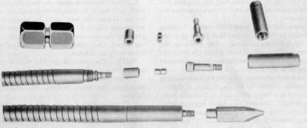
9A5. Disassembly. (See Figure 9-1.) Remove
the motor supporting plate (piece 13). Remove
the cotter pin (piece 28), the nut (piece 27) and
washer (piece 26), and remove the pulley (piece
83) using the puller. Remove the drive end cover
(piece 14). Remove the gear housing (piece 15).
Remove the cotter pins from the shaft nuts (piece
77), and remove the nuts. Remove the bolts
(pieces 64 and 70), the dowel retainer and dowels
from driven gear (piece 19) and remove the gear
from the hub. Remove the bearing lockouts
(piece 42) and the lockwashers (piece 44) from
the rotor shafts. Using the gear puller provided
in the spare parts box, remove the driven gear hub
(piece 20) and the drive gear (piece 18) from the
shafts and remove the keys.
NOTE. The driven gear must be loosened from
the hub and removed first before attempting to
remove the drive gear. If this is not done, the
rotors will be damaged.
Match mark the bearing retainers with the end
plates so that the parts may be reassembled in the
same relationship. Remove the bolts (piece 62)
from the bearing retainer plate (piece 46) and,
by using the puller, pull out bearing retainers
(piece 32). This will also bring out the bearings
and oil slingers. Remove the shims (piece 43),
carefully noting their number and position so that
they may be reinstalled correctly.
On the drive end of the compressor, remove the
bearing lockouts and lockwashers (pieces 42 and
44). Remove the oil slinger and spacer (piece 47)
from the driven shaft. Remove the bolts (piece
63) from the bearing retainers (piece 32). By
means of the puller, the bearing retainers with
bearings and oil slingers may be pulled out. Remove the packing glands (piece 53) from the
shafts. Remove the shaft sleeves (pieces 36 and
37).
Match mark the end plates with the cylinder
so that the parts may be reassembled in the same
relationship. Remove the bolts and lockwashers
(pieces 61, 80, and 75) that hold the drive end
plate (piece 10) to the cylinder. Remove the
end plate from the cylinder. The dowels (piece
81) that position the end plate to the cylinder
should remain in the cylinder. The end plate
at the gear end of the compressor (piece 10)
may be removed in the same manner after the
shafts and rotors have been removed. Remove
the packing (piece 51) from the end plates.
9A6. Assembly. (See Figure 9-1.) Before assembling the compressor, all parts should be
thoroughly cleaned and inspected. Any slight
burrs or rough edges on the cylinder or end plates
should be removed with crocus cloth. Install the
shaft sleeves (pieces 36 and 37), packing (piece
51), and packing glands (piece 53) in both end
plates. The sleeves for the gear end (piece 36)
have a smaller inside diameter than the sleeves
for the drive end (piece 37).
Coat the face of the gear end plate (piece 10)
and the cylinder (piece 1) with Perfect Seal No.
4, manufactured by the P. O. B. Manufacturing
Co., Cincinnati, Ohio, or an equivalent seal.
Place the end plate in position over the dowels
in the cylinder. Install the bolts and lockwashers
(pieces 80 and 75) and tighten them evenly.
Place the cylinder upright on the end plate. Install the drive shaft and rotor into the cylinder
with the gear end down. Turn the keyway in
the shaft to the left (looking at the top of the
compressor). Install the driven shift and rotor
into the cylinder, gear end down and keyway
in the shaft to the left (looking at the top of the compressor).
NOTE. The drive shaft is on the right when
assembling the compressor in this manner. The
keyways in both shafts must be to the left or to
the right (looking at the top of the compressor).
Coat the faces of the drive endplate (piece 10)
and the cylinder with Perfect Seal No. 4 or equivalent. Install the drive end plate over the shafts
and over the dowels in the cylinder. Install the
bolts and lockwashers (pieces 80 and 75) and
tighten evenly. Install the bearing retainers
(piece 32) with the oil slingers (piece 34) and
bearings (piece 35). Make certain that the oil
seals (piece 54) are in place in the grooves in
the retainers. It will be necessary to press the
bearings on to the shafts by using special tools.
Make certain that the pilot hole in the bearing
retainer lines up with the dowel in the end plate.
NOTE: If the bearings and oil slingers have
been removed from the bearing retainer, they
should be reassembled before installing them over
the shafts. The oil slinger is installed with the
large diameter toward the inside of the retainer
away from the bearing. The bearing is installed
with the smooth side next to the oil slinger.
Make certain that the shims (piece 43) are installed between the bearing retainers and the end
plate at the gear end of the compressor. Install
the bearing retainer plates (piece 46) at the gear
end and install and tighten the bolts. Install the
lockwashers (piece 44) and locknuts (piece 42)
in the gear end of both shafts. Tighten the locknuts and turn down the tang of the lockwashers
into the slot of the locknut.
NOTE. The gear end locknuts and bolts must
be tightened first to prevent pulling the shafts in
the rotors.
Check the rotor end clearance which should be
0.009 to 0.011 inch at each end. If necessary, add
or remove shims until the proper clearance is obtained. Install and tighten the bolts holding the
bearing retainers at the drive end. Install the
lock wire. Install the spacer (piece 48) and oil
slinger (piece 47) on the drive end of the driven
shaft. Install lockwashers (piece 44) on the drive
end of each shaft and install and tighten the locknut (piece 42). Insert the key (piece 25) in the
driven shaft (piece 21) and press the driven gear
hub (piece 20) into place. Insert the key (piece
25) in the drive shaft (piece 22) and press the
drive gear (piece 18) into place using the special
tool. With the keyways in both shafts to the right
(facing the gear end of the compressor), and with
the marked tooth space on the driven gear (piece
19) meshed with the marked tooth on the drive
gear, push the driven gear into position over the
hub using the special tool. Install the dowels
(piece 59), dowel retainer plate (piece 58) and
bolts (pieces 64 and 70). Tighten the bolts and install the lock wire. Install and tighten the shaft
nuts (piece 23) on both shafts. Insert the cotter
pins.
9A7. Clearances. Check the rotor clearances to
see that they are within the following limits:
Rotor to rotor
0.014-in. to 0.018-in.
Rotor to end plate-drive end
0.009-in. to 0.011-in.
Rotor to end plate-gear end
0.009-in. to 0.011-in.
Rotor to cylinder
0.006-in. to 0.009-in.
The rotor end clearances can be adjusted by
varying the thickness of the shims between the
bearing carrier and the end plate at the gear end.
61
If the rotor to rotor or rotor to cylinder clearances
are incorrect, the gears and bearings should be
checked for wear.
CAUTION. Do not drive against the shaft or
any part mounted on the shaft after the thrust
bearings (piece 35) have been clamped in place by
the retainer plate (piece 46). Cover the sealing
faces of the motor supporting plate (piece 13)
and the cylinder with Perfect Seal No. 4 or equivalent. Install the plate on the cylinder, insert
and tighten the bolts securely. Shellac a new
gasket (piece 55) to the drive end cover (piece 14),
grease the gasket and the face of the end plate
and install the cover. Shellac a new gasket (piece
56) to the gear housing (piece 15), grease the
gasket and face of the end plate and install the
gear housing. Install the pulley (piece 83),
washer (piece 26), and nut (piece 27) on the drive
shaft. Tighten the nut and install a cotter pin
(piece 28).
9A8. Mounting the compressor on the unit. Place
a new gasket from the spare parts box on the top
head of the distilling unit and then place the compressor over the stud bolts. Replace the lock
washers and nuts and draw down the nuts uniformly. After mounting the compressor make
certain that it may be easily turned by hand and
that it does not bind or strike anywhere. Replace
all of the oil piping around the compressor and
install the lagging. Replace the insulating board.
Replace the motor on top of the compressor and
bolt it securely to the motor supporting plate
attached to the top of the compressor. Replace
the pulley on the compressor and attach the belts,
tightening the belts by means of the variable pitch
drive. Replace the pulley guard. Connect up the
motor leads. Place the proper amount of Navy
Symbol 9370 (SAE 40) oil in the compressor.
9A9. Preparation of the compressor for service.
Start the distilling unit and observe the compressor while the unit is starting up; observe its operation carefully for a period of 2 hours after
distillation has started. If the compressor shows
no signs of sticking during this period, it will give
satisfactory service. Should the compressor stop
or bind during this operation, stop the compressor
and allow it to cool until it turns freely by hand
and then start the unit again.
B. CLEANING
9B1. Cleaning. At present (Jan. 1955) the acid
cleaning method has almost entirely replaced the
mechanical method, however, the mechanical
cleaning equipment is carried on board tenders
and could be used if acid cleaning equipment or
material was unavailable. Both methods of cleaning are described in the following sections.
When mechanical cleaning was the only method
used, the evaporator could be operated for 400
hours before cleaning. The absolute operating
limit was 500 hours.
The heat exchanger was cleaned after 200 hours
of operation and the operating limit was 250 hours.
Rotameters, manometers and flow-control valves
were cleaned each time the evaporator was
cleaned, or more often if necessary.
With the acid cleaning method, the cleaning
interval is every 250 hours of operation. Less
time is consumed and less work necessary to acid
clean the distillers than to mechanically clean
them. The heat exchanger requires cleaning at
least each 250 hours of operation and, since the
acid method cleans the heat exchanger, evaporator
and all the connecting piping at the same time,
the whole unit is cleaned with the heat exchanger.
A description of the mechanical method will be
found in the following sections.
9B2. Cleaning crew. Two men comprise a cleaning crew. Unless a foot switch is provided, one
man should operate the motor and one man should
clean the tubes. The motor is turned on or off at
the direction of the man cleaning the tubes. Make
certain that the belt has sufficient slack so that it
will slip if the bit becomes jammed in the tube.
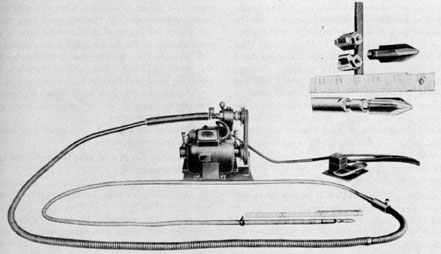
9B3. Shear coupling assembly. (See Figure 9-2.)
To provide protection for the small flexible shaft
against excessive torque loads, a shear coupling
assembly is attached to the cutter bit end of the
flexible shaft. The feature of this assembly is a
hexagonally shaped shear pin so constructed that
it will break under excessive loads. The ends of
the pin fit into hexagonally shaped housings,
which in turn are enclosed in a common casing
62
Figure 9-2. Shear coupling assembly.
which screws on to the cutter bit end of the flexible
shaft casing. (This easing has a left-hand
thread.) When the pin breaks, its broken ends
can be easily removed from their housings and a
new pin inserted.
9B4. Cleaning the evaporator. The following
procedure should be observed in cleaning the
evaporator:
a. Remove the section of insulation over the
manhole.
b. Remove the manhole with the wrench provided in the spare parts box.
NOTE. If necessary, rig up a platform at
about the level of the bottom of the evaporator.
c. Open the drain valve at the bottom and drain
the evaporator (use wire if the line clogs).
d. Remove the bottom circular insulation.
e. Disconnect and remove the eight immersion
heaters with the wrench from the spare parts box.
Plug the heater connections with the 3/4-inch pipe
plugs from the tube cleaner box.
f. Clean the scale from the heaters while they
are still wet.
g. Disconnect the overflow piping from the
handhole at the bottom of the evaporator and plug
the connection with a 1-inch or 1 1/2-inch pipe plug
from the tube cleaner box.
h. Start the feed pump. Open the feed valve
and fill the evaporator so that the water level is
about 1/8 inch below the tops of the tubes. Secure
the feed valve and pump.
i. Place a light inside the evaporator.
j. Disconnect the feed line from the inside shell
of the evaporator at the union and lift out the
pipe.
k. Using the special wrench from the spare
parts box, unscrew the overflow funnel pipe and
remove it.
l. Chip the scale from the compressor discharge
pipe and underside of the baffle. Chip the scale
from the shell of the evaporator about 4 inches
above the tube plate. It is advisable to cover the
tube plate to prevent big chips from falling into
the tubes.
m. Remove the motor and flexible shafts from
the tube cleaner box and connect them as follows
Couple the large flexible shaft and casing to the
driving unit by inserting the coupling attached to
the flexible shaft into the keyed hole in the
countershaft spindle. Screw the casing coupling
nut tightly to the threaded hub of the eccentric.
The 1/2-horsepower motor speed is 1,725 rpm.
Lift the belt guard and place the belt on the large
motor pulley, and the small countershaft pulley.
This setting of the belt will produce 3,450 rpm
speed at the countershaft.
NOTE. To set the speeds or adjust belt
tension, pull out the small handle and turn the
eccentric to loosen the belt. Place the belt on the
desired pulleys, turn the eccentric in the opposite
direction to tighten the belt, and replace the
handle in a locking position. Do not adjust the
belt tension too tightly, but allow slack so that the
63
338450 O-55-6
belt will slip in the event that the cleaning tool
becomes jammed in a tube. Be sure to replace the
belt guard.
Couple the 9-foot long 0.615-inch o.d. casing
assembly by threading the shaft coupling to the
end of the large shafting. Put grease in the
bronze casing coupling, slide it over the joint, and
secure the thumb nut to the section near the end
of the large shaft.
The 9-foot extension cable for the tube cleaning
equipment consists of an 1 1/32-inch o.d. flexible
shaft inside a heavy 0.615-inch o.d. double interlock casing. The assembly has a hexagon shear
shaft coupling in the thrust end housing of the
casing assembly (cutter bit end). This shear
coupling may be replaced by unscrewing the end
fitting of the casing. This fitting has a left-hand
thread. (See Figure 9-2.)
Three accessories are provided for cleaning the
3/4-inch tubes, the choice of which is dictated by
the nature of the deposit in the tubes. The
accessories are the following:
1. Carbide tipped cutter bit. The cutter bit is
the best and quickest method of removing hard
scale formed by normal operation using untreated
sea water feed. When using this bit, the tubes
must be full of water. It should be used at 3,450
rpm and will clean about three tubes per minute.
2. Expanding wire brush. The expanding wire
brush will readily remove soft scale usually
formed from treated sea water feed. It will also
remove hard scale if worked up and down in the
tube for a long enough period. The tubes must
be full of water or a stream of water must be
flowing down the tubes when the expanding brush
is used. It should be used at 3,450 rpm and will
clean about three tubes per minute if the scale
is soft. It may take 45 seconds or longer per tube
if the scale is hard.
3. Vibrating head. The vibrating head must
always be attached to a flexible holder. It will
remove any type of deposit. It may be used with
the tubes full of water or completely dry. It
must be used when it is impossible to clean the
tubes in the presence of water. The vibrating
head should be used at 3,450 rpm and will take
30 seconds to 2 minutes per tube, depending on
the type of scale. After using the vibrating head,
the tubes must be polished with the expanding
brush.
n. Place the heavy shaft so that the smaller
shaft will lie in a straight line with no short
bends. Grease the large cable by means of the
grease cup (about 8 to 10 shots) and connect by
plugging the tube cleaner motor cord to the lighting circuit. Add more grease to the large cable
about every 15 minutes.
NOTE. The motor is for 110 volts d.c. on
d.c. voltage vessels.
o. Examine the scale, select the proper cleaning
tool from the small toolbox, and proceed as
follows:
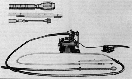
1. Cleaning 3/4-inch tubes with the cutter bit
(Figure 9-3). The tubes must be full of water.
(a) Attach the cutter bit to the end of the small
shafting.
CAUTION. The cutting edges of the tool are
tipped with tungsten carbide which is quite brittle.
Do not drop the bit or strike the cutting edges on
metal surfaces.
(b) Start the motor and proceed to clean the
tubes by passing the bit through each tube once.
NOTE. Unless a foot switch is provided, one
man should operate the motor and one man should
clean the tubes. The motor is turned on or off at
the direction of the man cleaning the tubes.
CAUTION. With the motor off, place the end
of the bit gently in the top of a tube. Hold the
cable about 6 inches back and line it up exactly
with the tube. Start the motor and let the bit
feed itself into the tube until the entire bit is in
the tube. Now exert pressure and pass the bit
through the tube. (The tubes are 16-14 inches
long. The fixed sleeve on the cable indicates when
the bit is completely through.) Pull the bit out
of the tube, stopping the motor just before the bit
is withdrawn, then go on to the next one, and so
forth. One bit should clean the evaporator several times. As the cutting edges become dull, more
pressure will be required to force the bit through
the tube. When the pressure is too great or the
bit begins to jam, the cutting edges should be
lightly honed. When honing is no longer possible,
the cutting edges should be reground.
Should the cleaning tool fail to turn while the
motor is running, the small hexagon shear coupling is probably broken. Remove the housing
from the end of the casing (left-hand thread) and
replace the shear coupling (Figure 9-2).
64
Figure 9-3. Cleaning gear with a cutter bit.
CAUTION. If the bit jams, secure the motor
immediately and free the bit. Try cautiously
again. If the bit continues to jam, mark the tube
and go on to the next one. After the remainder
of the tubes have been cleaned with the cutter bit,
clean the marked tubes with the expanding brush
or vibrating head, as directed in Step 2 or 3 following. The thin film of scale left by the bit in
the expanded portion of the tubes will cause no
trouble or loss of efficiency and need not be
removed.
(c) After all the tubes have been cleaned, secure
the motor, unscrew the bit (wrenches will be found
in the tube cleaner box), dry, oil, and replace the
bit in the box.
NOTE. If the small cable runs hot in cleaning
the tubes, it should be greased. In any event, this
cable should be greased at least once every hour of
continual use. To grease the smaller cable, remove
the flexible shafting from the inside casing and
wipe with grease as it is reassembled. If the large
cable runs hot, add more grease to the grease cup.
2. Cleaning 3/4-inch tubes with the expanding
wire brush. The tubes must be full of water.
(a) Attach the expanding brush to the end of
the small shafting.
(b) Start the motor and work the expanding
brush up and down the tube. Make certain that
the brush goes entirely through each tube. The
operator can tell by the vibrations of the brush
when all the scale is removed. If the scale is soft
it should be possible to clean two or three tubes
per minute. A minute or more per tube may be
required to remove the hard scale.
(c) Remove the expanding brush, dry, oil, and
replace in the box.
3. Cleaning 3/4-inch tubes with the vibrating
head. The tubes may be full of water or dry.
(a) Attach the flexible holder and vibrating
head to the end of the small shafting.
(b) Start the motor and work the vibrating
head slowly up and down the tube. Keep the
vibrating head in motion. Do not permit it to
remain at one spot in the tube for any length of
time. The operator can tell by the vibrations of
the brush where patches of scale remain and when
it has all been removed. Clean each tube completely before proceeding to the next one. A
minute or more may be required per tube, depending on the hardness and type of scale.
65
NOTE. After using the vibrating head, the
tubes must be polished with the expanding brush.
(c) Disassemble the overflow piping between the
evaporator and the heat exchanger. Straight sections of 1-inch or 1 1/2-inch I.P.S. (Iron Pipe
Size) may be cleaned with the vibrating head
for the 1-3/4-inch o.d. tubes attached directly
on the small shafting (Figure 9-4). Elbows
or bends in 1-inch I.P.S. pipe and sections
of 3/4-inch I.P.S. pipe may be cleaned with the
3/4-inch vibrating head. A stream of water
must be flowing through the section of pipe being
cleaned, otherwise the head will become clogged
with scale.
(d) Remove the vibrating head and flexible
holder, dry, oil, and replace in the box.
9B5. Cleaning the 1 3/4-inch o.d. heater tubes and
inside of overflow pipe. The scale should be removed in the presence of water (Figure 9-3).
a. Select the vibrating head and flexible holder
for the 1 3/4-inch o.d. tubes and attach it to the
end of the small shafting. Use a cleaner shaft
speed of 3,450 rpm.
b. Start the motor and work the vibrating head
slowly up and down the heater tubes until all the
scale is removed.
NOTE. Place a clamp on the large shafting to
serve as a guide to indicate when the vibrating
head is entirely through the 16 1/4-inch long tubes.
c. Clean the inside of the overflow pipe in the
same manner as the heater tubes were cleaned.
d. Remove the vibrating head, flexible holder,
and small shafting. Dry, oil, and replace the
vibrating head and flexible holder in the box.
e. Attach the 1 3/4-inch o.d. expanding brush
directly to the end of the large shafting, and
polish the heater tubes.
f. Remove the 1 3/4-inch o.d. expanding brush,
dry, oil, and replace in the bag.
9B6. Cleaning 4-inch o.d. tube located in the center of the evaporator.
a. Drain the water from the unit. Should the
flow stop before draining is complete, insert a wire
in the drain line to start the flow.
b. Connect a hose to the ship's water supply and
place the end inside the evaporator. Direct a
small stream of water down the sides of the 4-inch
tube.
CAUTION. Do not clean the 4-inch tube when
it is full of water.
c. Select the large expanding brush and attach
it to the end of the large shafting.
Figure 9-4. Cleaning gear with a vibrating head and expanding wire brush.
66
Figure 9-5. Water nozzle.
d. Remove the belt guard and place the belt on
the sit all pulley and the large countershaft pulley
to give the lowest shaft speed, approximately 1,725
rpm.
CAUTION. The 4-inch brush must be used
only at low speed. The operator at the motor
should keep his hand on the switch so that he can
secure it instantly at the direction of the operator
cleaning the tube.
e. Place a stop on the sleeve of the large cable
that the whole brush will not go entirely
through the 16 1/4-inch long, 4-inch o.d. tube.
f. With the motor off, place the brush in the
large tube. Start the motor and work the brush
up and down the tube, taking care that the brush
does not come out of the tube while the motor is
running. Secure the motor before removing the
brush from the tube.
g. Remove the large brush, dry, oil, and replace
in the box. Disconnect the large shafting, dry,
oil, and replace in tube cleaner box. Do not
attempt to coil the shafting too tightly. Utilize
the full width of the tube cleaner box. Replace
the motor and other parts.
h. Remove the 4-inch handhole. Remove the
scale accumulation by hand and flush out the scale
with a water hose from the bottom head of the
evaporator.
i. Replace the handhole, the overflow tube with
funnel, the inside feed connection and the manhole
cover.
j. Clean the rotameters, manometer and flow
control valve.
k. Reassemble the overflow piping.
9B7. Cleaning the heat exchanger. The heat exchanger using 3/4-inch o.d. finned tubes should be
cleaned as follows:
a. Remove the covers from both ends.
NOTE. Remove the nuts from every stud before attempting to remove the covers. However,
it is not necessary to break the gasket joint
67
between the small plate and the inlet end cover. Do
not remove the small plate from the inlet end
cover except after about 4,000 hours.
b. Connect the tube cleaning motor and flexible
shafts as for cleaning the 3/4-inch o.d. tubes of the
evaporator. (See Figures 9-3 and 9-4.) Connect the water hose with nozzle for the 3/4-inch
o.d. tubes attached. (See Figure 9-5.)
c. Examine the scaled tubes and select the
proper tool.
NOTE. The lower three or four rows of tubes
in the exchanger will usually have a hard scale
similar to that found in the evaporator tubes.
The carbide tipped cutter bit is the best and
quickest tool to remove a hard scale and should be
used in these tubes.
The upper five or six rows of tubes in the exchanger will usually have a soft slime-like scale.
The expanding wire brush will remove this type
of scale quite effectively and should be used in
these tubes. Both of these attachments should
be used at 3,450 rpm. One man should stand by
the motor to operate the switch, a second man
should clean the tubes, and a third man should
handle the water hose.
d. Insert the hose nozzle in the end of heat exchanger tube at the less accessible end and run a
small stream of water through the tube. With
the proper tool attached, mark off a point on the
cable about 49 inches from the end. Start the tube
cleaner motor and pass the cleaner through the
tube, withdrawing the hose nozzle just before the
cleaner reaches the nozzle. Care should be taken
to line up the cable with the tube when starting
the cleaner tool into the tube.
NOTE. A stream of water must always be
flowing through the tubes while cleaning.
CAUTION. Should the bit jam, secure the
motor immediately and free the bit. Try cautiously again. If the bit continues to jam, mark
the tube and go on to the next one. Clean the
marked tubes with the vibrating head or expanding wire brush. Should the cleaning tool fail to
turn while the motor is running, the small hexagonal shear coupling is probably broken. Remove
the housing from the end of the casing (left-hand
thread) and replace the shear coupling (Figure
9-2).
e. Dry, oil, and replace the tube cleaning gear
in box.
NOTE. Be certain to disassemble and grease
the 9-foot shafting before replacing in the box.
f. Remove the 3/4-inch brine overflow pipe connection at the bottom of the exchanger and clean
the pipe. Connect to the heat exchanger after
cleaning.
g. Clean the end covers of the exchanger and
replace, using new gaskets.
9B8. Instructions for resharpening cutter bits. A
hone is provided in the tube cleaning box for
sharpening the tungsten carbide cutting edge.
When the bit cannot be sharpened by the hone, it
must be ground. A diamond impregnated or silicon carbide wheel should be used.
a. Each flute of the cutter bits must be ground
separately.
b. Grind only on the cutting edges, never on the
diameter, noting particularly-that the 15 degrees relief
angle is maintained.
c. If a wheel is used:
1. Never permit the wheel to become loaded.
Keep it clean.
2. Keep the bits in motion while passing the
wheel, avoiding any stationary contact.
d. Be certain that the cutting edge of each tungsten carbide bit is indexed and ground identically
so that each flute does the same amount of cutting.
9B9. Acid cleaning. Naval vessels employing
vapor compression distilling units, particularly
submarines, maintain a very limited reserve of
distillate. It is therefore important to maintain
distiller efficiency at the highest possible level and
to assure a minimum of lay-up time for removing
the scale deposits from the heat transfer surfaces.
The mechanical method of cleaning is inefficient,
time consuming and somewhat damaging to the
heat transfer surfaces. As a result, distilling
units were generally operated to the point of lowest tolerable capacity, necessitating long and expensive overhaul periods.
In consideration of the foregoing, an acid cleaning method has been adapted for submarine usage.
9B10. Intervals of cleaning. Clean distilling
plants with the sodium acid sulphate solution,
normally after each 250 hours of operation, or
when the steam chest pressure reaches 6 psi.
9B11. Cleaning crew required. One man can
efficiently clean one distilling plant in 2 hours
time if equipment is kept available and in a good
state of readiness.
9B12. Equipment required.
a. One copper or nonferrous metal container of
25-35 gallons capacity, fitted with a bottom discharge line and suitable strainers, valves and a fine
mesh screen cover.
b. Suitable hoses for connecting the brine tank
to the acid tank and the acid tank to the feed
pump. It is suggested that all hose couplings be
numbered to insure tight make-up.
c. 50 pounds of sodium acid sulphate (niter
cake) for each distilling plant to be cleaned.
9B13. Preparations for cleaning.
a. Fill evaporator as for normal operation, and
turn on all heaters.
b. While waiting for unit to heat up, carry out
normal prestarting routine, checking
1. Tightness of belts.
2. Compressor oil level.
3. Bypass valve open.
4. Motor rheostat turned down.
5. On converted units, while cleaning, check
open evaporator level safety line stop valve.
c. Make up mixture of sodium acid sulphate and
water (salt or fresh), following formula:
Sodium acid sulphate (lbs.) =capacity of
unit (gph) X 4/5
This makes a mixture of about 12 percent
strength.
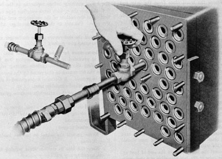
d. Make necessary connections, with hoses to
feed pump from acid tank, and from brine tank to
acid tank. (See Figure 9-6.)
NOTE. Be sure that the hose from the acid
tank to the feed pump is filled with the acid solution and free of air.
e. Line up condensate and brine systems as in
Figure 9-7.
9B14. Procedure for cleaning.
a. When unit is ready to start, follow normal
starting procedures.
b. When balanced, cut feed rate to about 50 percent normal flow. To maintain distillate balance
this will require cutting off heaters.
c. Shift feed pump suction from normal source
to acid tank suction line. Secure the normal
source.
d. Blow or drain first 20 gallons of brine-condensate mixture to bilge. Afterwards blow all
acid-brine-condensate mixture to acid tank. This
keeps acid solution at full strength.
e. Maintain steam chest pressure at four psi,
using bypass valve.
f. Continue circulating acid-brine-condensate
mixture through the unit for 1 1/2 hours.
g. Shift the feed pump suction to the normal
source after cleaning period is completed, and
discharge all distillate to the bilge, making frequent Kleinschimdt conductivity tests until distillate is acceptable for regular use. One hour's
operation should restore maximum purity.
NOTE. If need for distillate is critical, it can
be run to the regular storage throughout the cleaning process, provided the Kleinschmidt conductivity tests taken on the distillate is within the
specified limits. This will require that the same
amount of water (salt or fresh) be added to the
mixture to keep it to the correct strength.
NOTE. Should the steam chest pressure remain high after returning to normal operation,
the distilling unit has not been properly descaled.
In such a case, repeat the cleaning process, using a
fresh charge of sodium acid sulphate mixture.
h. Shift the distillate to its regular storage and
continue normal operation.
i. When secured, rinse all equipment with fresh
water and stow away for future use.
9B15. Safety precautions.
a. Sodium acid sulphate is inert in the dry
state. Store in moistureproof containers.
b. It is only mildly acidic when in use and will
not harm the skin or clothing. Normal safety
precautions should be followed to prevent contact
with the eyes or with skin for prolonged periods.
Mild irritations will result.
c. Insure that all equipment is kept clean, and
if acid container is used as a rag or waste container, clean thoroughly of all oil and waste before
using again.
d. Keep valves in systems in good condition, to
insure there is no possible contamination of distillate when in normal use.