As of the date of revision of this text (Jan. 1955)
there are a number of new types of submarines in
commission or being built. Fresh water requirements, space availability, and other variable conditions have brought about the installation of
several different distilling systems on these
submarines.
In Section 6A1 mention is made of these new
models. In this chapter, a section is devoted to
a brief description of each. Some of them have
not yet been fully evaluated under actual operating
conditions, and it is possible that some changes
will be made. Therefore, no detailed descriptions
are attempted in this discussion.
All of these models except the Soloshell employ
the vapor compression principle and all are entirely electric. They differ from the Model X-1
(AAA-1) only in capacity, physical size, and
small mechanical and operational details. The
Soloshell is a steam evaporator operating on the
vacuum principle.
A. BADGER MODEL V-1
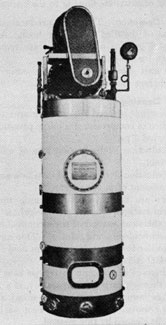
10A1. General information. This is a vapor compression unit of the same rated capacity and similar in size and appearance to the Model X-1 (or
AAA-1) but of modified design.
The Model V-1 was designed to operate under
a vacuum of approximately 22 inches of Hg. This
meant that the boiling temperature of the sea
water feed could be lowered, with a resulting lower
rate of scale formation and a softer type of scale
deposit. The unit could, as a result, be operated
for longer periods before cleaning. Also, since
the unit is completely sealed of from the atmosphere, the pressure fluctuations when snorkeling
should have no affect on the operation of the unit.
Two of these units were installed on each of the
SS563 class submarines. Under actual operating conditions they failed to prove entirely satisfactory and some alterations to the original design
were necessary.
The following is a brief description of the
original installations, a discussion of some of the
problems encountered under actual operating
conditions and the alterations made to insure satisfactory operation.
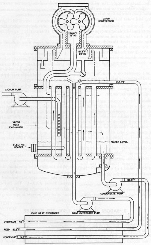
10A2. Description. The distilling unit consists of
two main parts, the evaporator and the heat exchanger. (See Figure 10-1.) The evaporator
has a vertical tube steam chest with a vapor separator above the steam chest for separation of
liquid particles from the vapor. A 3-lobed vapor
compressor, fitted with a bypass valve for starting,
is mounted on top of the evaporator. A 12-hp
electric motor is mounted on top of the evaporator
and drives the compressor.
The heat exchanger, connected to the evaporator
by piping, is of the double tube type. Its function is to heat the incoming feed water by absorbing heat from the condensate and the brine
overflow. All of these features are similar in construction and location to the Model X-1.
10A3. Distilling cycle. The cycle is started by two
horizontally placed electric heaters which heat
the distilled water in the bottom of the steam
chest. Heat from the distilled water is transferred through the tubes of the steam chest to the
feed water inside of the tubes (after the unit is
in operation, the feed water is also preheated in
the heat exchanger). The vapor from the boiling
feed passes through a vapor separator to the vapor
compressor, where its pressure (and temperature)
is raised.
The compressed steam, still under a vacuum
relative to the atmospheric pressure, passes from
the compressor to the steam chest where it gives
up its latent heat of vaporization to the feed
water as the steam condenses.
A distillate trap in the steam chest keeps the
level of the distilled water high enough to cover
(70)
Figure 10-1. Schematic sketch vapor compression distilling unit Model V1.
71
the two heating elements. These two thermostatically controlled heaters supply the additional
heat to the distillate necessary to balance the heat
losses. The heat from the distillate is transferred
to the incoming feed water in the heat exchanger.
10A4. Pumps. In order to maintain a vacuum,
a horizontal centrifugal displacement type vacuum
pump is used to draw the air and noncondensable
gases from the steam chest through a pipe extending into the steam chest. An arrangement
of baffles is used to direct the air to this perforated
pipe. These noncondensable gases are discharged
through the heat exchanger and into the
atmosphere.
Since the unit operates on a vacuum, a brine
pump is required to pump the brine from the evaporator to the heat exchanger, and a condensate
pump is required to remove the distillate and
pump it through the heat exchanger.
10A5. Alterations. As previously mentioned, this
model did not prove entirely satisfactory as designed. Under actual operating conditions, it
was extremely sensitive to the variable conditions
encountered. It proved difficult to maintain the
vacuum. Considerable trouble was experienced
with the compressor seals and when the unit was
under a vacuum, it was very difficult to locate and
rectify air leaks into the system.
As a result, changes were made to the original
installations. Conversion kits were supplied
which, after installation, permitted operation of
the units under a pressure (similar to the converted Model X-1) instead of a vacuum. This
conversion greatly increased the capacity of these
units.
In order to accomplish this conversion, several
mechanical changes were made:
a. The vacuum pump, no longer necessary, was
eliminated.
b. The vacuum operated compressor was replaced with one designed for pressure operation.
c. A new compressor drive was installed to suit
the new pressure conditions.
d. A pressure controlled (pressure-static)
switch was provided to replace the temperature
controlled (thermostatic) switch for control of
the heaters.
e. Vacuum gages were replaced with pressure
gages.
f. Changes were made in lines and flowmeters
to accommodate the increased capacity obtained
by pressure operation. (Before conversion the
output of distilled water was 50 to 55 gph; after
conversion the condensate rate with a clean unit
increased to 75 to 80 gph.)
g. At present the brine and condensate pumps
are retained. Since the unit now operates under
pressure, they are not needed to remove the liquids
from the evaporator, but the brine pump is used to
pump the brine overboard, and the condensate
pump is used to deliver the fresh water through
the heat exchanger to the distillate tank, which is
at a higher level than the heat exchanger. A proposed rearrangement, whereby the distillate tank
is lowered and the method of brine disposal
changed, would render these pumps unnecessary.
h. Operating under pressure, a desuperheating
system became necessary. A line equipped with
an orifice from the distillate pump to the compressor provides the desuperheating water.
With the described alteration, the methods of
operation, control, and maintenance are very
nearly the same as those described for the converted Model AAA-1. The increased capacity
and other advantages gained by conversion, more
than offset the decrease in operating time between
cleanings.
B. BADGER MODEL WS-1,300 GPD DISTILLER
10B1. General description. The Model WS-1
vapor compression distilling unit is similar to the
Model X-1 in its principles of operation. It is a
small compact unit requiring little space, thus its
selection for use aboard the T-Class of submarines. One of these units is installed on each of
this class vessel.
The distilling unit consists of three main parts;
the evaporator, the heat exchanger, and the vapor
compressor.
a. The evaporator has a vertical tube type steam
chest with a vapor separator space above it for
separating liquid particles out of the vapor. A
motor-driven water sealed type vapor compressor, fitted with a bypass valve for starting, is
mounted in the upper section of the evaporator.
The lower portion is fitted with a boiler section
in which two 2,000-watt electric heaters are
mounted horizontally. One of the two heaters is
controlled automatically to maintain proper evaporator operating pressures.
These heating elements project into the lower
part of the boiler section, which acts as a reservoir
for the distillate. With this arrangement, the
heaters add heat to the distillate instead of directly to the sea water feed. Same of this added
heat is transmitted to the feed water in the upper
part of the boiler section through the plating
separating the two liquids, and some of the heat
is given up to the cool feed water in the heat
exchanger.
b. The heat exchanger is the horizontal double
tube type, with all features of the heat exchangers
used with Model X-1.
c. The vapor compressor is the liquid sealing
ring type, installed in the evaporator. Motive
power is supplied by a 5-hp motor, with a belt
drive, mounted on the evaporator casing.
10B2. Cycle. (See Figure 10-2.) Feed is supplied by a feed pump through the rate-of-flow
controller (feed pressure regulator), feed control
valve, and feed rotameter to the heat exchanger,
where it is preheated by the hot distillate. Feed
water leaves the heat exchanger and goes to the
evaporator, where it is fed into the central downtake tube. It then picks up heat from the distillate and steam in the steam chest as it rises up
through the tubes.
Vapor, from the boiling feed at the top of the
steam chest, passes up through the vapor separator
where any entrained liquid particles will be separated from the vapor. The compressor takes a
suction from the separator and discharges down
to the steam chest where the steam, on the outside
of the tubes, gives up its latent heat to the incoming feed inside the tubes, as the steam condenses.
Every pound of steam that condenses generates a
pound of vapor from the feed water for the compressor suction.
The distillate then flows down the distillate
return pipe to the boiler section where it is drawn
off through the heat exchanger to storage. The
condensate discharge line is at such a height as to
keep the heaters in the boiler section covered
continuously.
These heaters start the operation of the unit by
heating the initial distillate, which in turn, heats
the cold sea water feed above it to its filing
point and generates the steam to start the vapor
compression cycle. During operation, the electric heaters supply additional heat so that a sufficiently high overflow rate can be maintained to
retard the formation of scale and balance the heat
losses, and so that the proper operating pressure
can be maintained in the unit. One of these
heaters is controlled, during the operation, by a
pressure operated switch to automatically maintain the proper balance.
The hot distillate flows from the boiler section,
through the heat exchanger, where it gives up
heat to the incoming sea water. It then flows
from the heat exchanger to a suitable distillate
collecting tank, here it can be tested and transferred to the ship's fresh water stowage tanks.
The brine overflow in the upper section of the
steam chest is drawn off through a funnel and
brine overflow line and passed through the heat
exchanger to the bilge. In the heat exchanger,
the brine gives up much of its heat to the sea water
feed.
Air and noncondensable gases are directed by
a system of baffles to a vent line in the steam chest.
These noncondensable gases are passed through
the heat exchanger and to atmosphere. The
amount of vapor and noncondensable gases vented
from the steam chest can be controlled by a needle
valve installed in the vent line.
20B3. Operation. The distilling plant is balanced and kept in a stable condition by slight adjustments of the feed rate and by the number of
electric heaters used. The unit operates on a
very sensitive heat balance and operates best when
all conditions remain constant. Balance is indicated by a compound gage which indicates the
pressure (or vacuum) of the vapor from the boiling feed.
The temperature of the sea water feed is a
determining factor controlling the amount of heat
necessary to hold the compound gage reading at
the proper pressure. Under most conditions the
automatically operated heater will be sufficient to
maintain this pressure. However, if the feed
water is very warm, the heat supplied by the compressor might be all that is necessary; or if extremely cold, both heaters, on continuously, might
73
be necessary to maintain the proper operating
pressure.
Under the varying conditions usually encountered such as rough seas, snorkeling, etc., the plant
is balanced with a compound gage pressure of 6
to 12 inches of water and a feed rate between 24 1/2
gph and 30 gph, depending on the condition of
scaling in the unit. As the heating surfaces become scaled, the feed rate should be increased.
During operation, the compressor discharge
pressure should be between 2 and 4 pounds. The
compressor sealing water valve should be adjusted
to keep the discharge pressure at a minimum.
If operating properly, this unit will produce
about 16 gallons of fresh water per hour (rated
capacity is 300 gallons per day) from an input of
about 25 gallons per hour of sea water. The distillate, made from sea water, will have less than
one part per million of salt.
10B4. Cleaning. The system is designed to be
cleaned by an acid cleaning method as was described for the Model X-1.
Need for cleaning is indicated by a rise in compressor discharge pressure. When the compressor pressure rises to 5 3/4 pounds the distilling
unit must be cleaned.
C. CLEAVER-BROOKS, 300-GPD DISTILLER
10C1. General information. The Cleaver-Brooks
300-gpd vapor compression distilling unit is a
small compact unit, adapted for use aboard the
K-Class submarines. One unit of this type is
installed on board each boat of this class.
The distilling unit consists of three main
sections:
1. Evaporator, consisting of the following:
a. Evaporator-condenser section.
b. Vapor head, containing two steam separators.
c. Bottom head and boiler section, containing
the two heaters.
2. Heat exchangers consisting of two heat exchangers connected in series.
a. The evaporator-condenser section of this unit
performs the same functions as the steam chest in
the Model X-1 or Model WS-1. Vaporization of
the sea water feed inside of the tubes and condensation of the steam around the outside of the
tubes, are the main functions.
b. The vapor head section contains two vapor
separators, a centrifugal separator, and a cyclone
separator. Circuitous passage through the separator baffles causes the vapor passing through
these separators to give up any entrained liquid
particles. The vapor head is also fitted with a
bypass valve which is used when starting or
cleaning.
c. The bottom head and boiler section is bolted
to the bottom, of the shell under the evaporator-condenser
section. The lens-shaped space between the lower tube sheet of the evaporator-condenser section and the bottom head forms a
reservoir for the feed water. Below this "feed
well" is the boiler, which acts as a reservoir for the
distillate. The 2 immersion type heaters project
horizontally into the boiler.
2. Heat exchangers.
Two identical heat exchangers of the interlocking coil type, connected in series, serve the same
purpose as the straight tube type used in other
models. The feed water passes around the coils
and the distillate and brine pass through the coils.
The feed water is heated and the brine and distillate are cooled in these heat exchangers.
3. Vapor compressor.
The vapor compressor is of the centrifugal blade
type driven through belts by a 3-hp electric motor.
10C3. Distilling cycle. The cycle is started by the
initial heating of the distillate in the boiler by the
two electric heaters. The boiling distillate, and
the vapor from it circulating around the tubes
of the evaporator-condenser section, heats the feed
water inside of the tubes to the boiling point.
This boiling action in the evaporator causes the
feed water from the feed well to percolate upward
through the tubes, some of it being converted to
vapor and the remainder returning to the bottom
section through the downtakes. (A trough welded
around the upper part of the shell, is connected by
3 channels, or downtakes, to the feed well below
the bottom tube sheet.)
During operation, a portion of this boiling sea
water feed is continuously discharged as "blowdown"
(brine) to prevent too high a salt concentration. This brine, or blowdown, is directed
through the heat exchangers to recover some of
the heat before the brine is discharged as waste.
Sea water feed is supplied continuously to the unit
to make up for the amount discharged as brine
plus the amount converted to vapor.
The sea water supply passes through a pressure
reducing valve and a flowmeter (flowrator) on
its way to the heat exchangers. In the two heat
exchangers, the feed receives heat from the brine
and from the distillate flowing (counterflow)
away from the evaporator.
The hot feed from the heat exchangers enters
the side of the evaporator-condenser section and
flows into the bottom section or feed well through
one of the three downtakes. In the feed well, the
sea water receives more heat from the boiler section directly below it. Then, as it rises through
the tubes, the hot feed receives the latent heat
from the condensing steam on the outside of the
tubes. Part of the feed is vaporized as it rises
through the tubes and part of it returns to the
feed well. A portion of the boiling feed drains
away through the blowdown outlet to the heat
exchangers.
The vapor, rising from the boiling feed water
passes through the 2 separators in the vapor head
and into the compressor suction. Particles of salt
water which are removed from the vapor in the
separators are collected and drained back to the
bottom section.
In the compressor, the pressure of the vapor is
raised to about 5 pounds per square inch. This
compression also raises the temperature of the
steam. The compressed steam from the compressor is forced into the steam chest, where it condenses and gives up its latent heat to the feed
water.
The condensate, or distillate, drains back to the
boiler and then through an overflow outlet in the
boiler to the heat exchangers where it imparts heat
to the cold feed water before being discharged to
stowage tanks. The distillate overflow outlet in
the boiler insures that the heaters remain immersed. These heaters remain on when the unit
is in operation and would burn out unless covered.
During operation, vaporization of part of the distillate is continuous. Some of the distillate is
used as a water seal for the compressor, a needle
valve and a "flowrator" being used to regulate the
amount of distillate flowing to the compressor.
10C4. Operation. This unit produces about 15
gallons of distilled water per hour. Approximately 2 gallons of sea water are required to
produce 1 gallon of distillate.
The unit should operate continuously for 500
hours before cleaning is necessary.
10C5. Cleaning.
Indications of need for cleaning are:
1. Rise in compressor discharge pressure above
the normal 5 psi.
2. Reduction in distillation rate of more than
10 percent.
3. Reduction in quantity of distillate compared
to the amount of power consumed.
There are 2 methods of cleaning used; the
chemical method, and the mechanical method.
The chemical method of scale removal employs
a sodium-acid-sulphate solution. One method is
very similar to the one described for acid cleaning
the Model AAA-1.
Mechanical cleaning; a drill type tube cleaner
is run through each tube separately, if a type of
scale has been formed which chemical cleaning
cannot remove. The coil type heat exchangers
cannot be cleaned by this method.
D. VAPOR COMPRESSION DISTILLING UNIT MODEL Y-1
10D1. General description. The Model Y-1 vapor
compression distilling unit is entirely electric and
rated at 1,000 gallons per day of distilled water.
It makes 45 to 50 gallons per hour of distilled
water, containing less than one part per million
of sea salt, from about 70 gallons per hour of
normal sea water and has a, constant blowdown
(overflow) of 20 to 25 gallons per hour. The
temperature of the distilled water (condensate)
will be within 15 degrees F. to 30 degrees F. of the sea water
feed temperature. The overflow temperature will
be about 30 degrees F. to 40 degrees F. above the feed water
temperature.
A distilling unit consists of three parts-the
evaporator, the heat exchanger, and the compressor. The evaporator has a vertical tube steam
75
chest with a vapor space above it fitted with baffles
to separate the liquid from the vapor. Three
electric heaters are mounted horizontally in the
boiler section, and are automatically controlled to
maintain the proper evaporator operating pressure. A three-lobe, positive displacement type
compressor is mounted on top of the vapor chamber, and its motive power is supplied by a 7 1/2
horsepower electric motor. The heat exchanger
is essentially a horizontal double pipe cooler.
Figure 10-4. Vapor compression distilling unit,
Model Y-1.
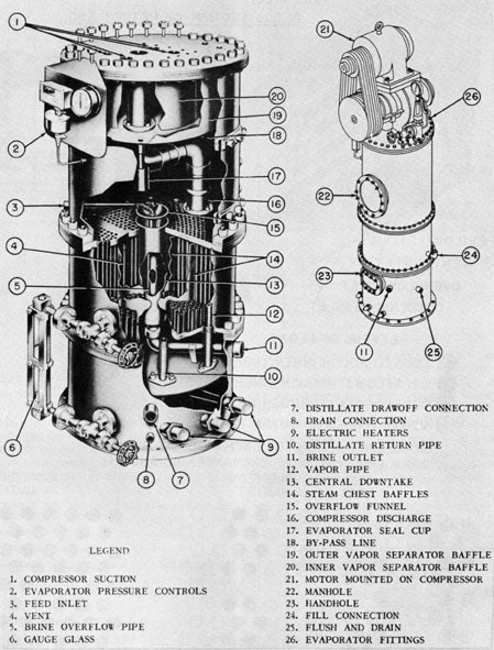
10D2. Evaporator. The evaporator (see Figure
10-13) consists of four main parts; the boiler
section, the vertical steam chest, the vapor separator, and the vapor compressor.
The boiler section is 22 inches in diameter by
9 1/4 inches high. It has connections for the three
2,000-watt immersion heaters which are mounted
horizontally in it. It also has a distillate drawoff
connection, the lower connection for the gage glass
and a 1/4-inch I.P.S. drain connection. As this
section contains the heaters it must always be filled
with distillate when heaters are in operation to
prevent them from burning out. During operation of the unit, water in the boiler section is
maintained at the boiling point. Hot vapors rise
through the 3/4-inch I.P.S. vapor pipe to the
steam chest. Distillate made in the steam chest
flows down through the 3/4-inch I.P.S. distillate
return pipe to the boiler section. The 1-inch
I.P.S. distillate drawoff connection from the
boiler section is so located to maintain a level of
water high enough to keep the heaters covered
with water at all times.
The vertical steam chest (see Figure 10-13) is
22 inches in diameter and contains 379 copper
nickel tubes 3/4-inch o.d. x 16 1/4 inches long. It
has a 4-inch o.d. tube as a central downtake or
circulating tube, and an overflow pipe which
maintains the proper liquid level in this section.
This overflow pipe consists of a funnel and a
1 1/4-inch I.P.S. tube centered in the central downtake and connected to the shell of the evaporator
in the feed water return section. The overflow
flows from the unit, passes through the heat exchanger, and discharges into the brine receiver.
The sea water feed boils inside the 3/4-inch o.d.
tubes at a pressure of between 6 and 12 inches
of water, while the steam from the compressor
condenses on the outside of the 3/4-inch o.d. tubes
at approximately three pounds gage pressure.
The hot distillate (condensate) flows from the
boiler section, through the heat exchanger, and
on to the distillate water receiver. Suitable baffles
in the steam chest direct the flow of vapor around
the tubes, and also direct the noncondensable
gases to a central point. A vent line is installed
at this point in the steam chest of the evaporator
to prevent the noncondensable gases from accumulating. To control the amount of vapor and noncondensable gases vented during the operation
of the unit an orifice plate (with 3/64-inch orifice)
is placed in the flanged joint at the vent outlet
of the evaporator.
Besides the connections mentioned above, the
steam chest also has the top gage glass connection, and a 3/4-inch I.P.S. fill connection. The
gage glass allows a visual check of the height
76
Figure 10-5. Evaporator fittings.
of the distillate. The fill connection is used to
fill the boiling section with enough water to cover
the immersion heaters.
Between the steam chest and the boiler section
is a feed water return section which contains a
4 1/4-inch x 8-inch handhole, a 1-inch I.P.S. overflow connection, and a 3/4-inch I.P.S. flush and
drain connection.
The vapor separator (see Figure 10-13) which
is fastened by brackets to the top head of the
evaporator, consists of a 22-inch shell containing
two concentric baffles. This baffle arrangement
allows the steam to pass into the compressor but
prevents any liquid entrainment from so doing.
Small particles of water separated by this arrangement collect on the bottom of the vapor separator and flow into the seal cup. The liquid
overflows the seal cup to the boiling sea water,
and relatively pure vapor passes on to the suction
side of the compressor. The pressure in the evaporator above the boiling sea water is indicated by
a compound indicating pressure gage connected
to the side of the evaporator. This section also
has connections for the following items located
in the outer shell; a 3/4-inch I.P.S. sea water
feed connection, and a 10-inch manhole.
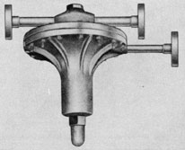
10D3. Vapor compressor. The vapor compressor
(see Figure 10-12) is a three-lobe, positive displacement type consisting of two rotors enclosed
in a special compact housing designed for bolting
on the top head of the evaporator. Each rotor
has three helical lobes designed to produce a continuous uniform flow of vapor. The vapor enters
the specially designed compressor housing at the
bottom and passes upward between the inner and
outer walls to the rotor chamber where it fills the
spaces between the rotor lobes as they roll apart.
This vapor is then carried by the rotors in the
spaces between the lobes around the cylindrical
sides of the housing producing a pressure at the
bottom as the lobes roll together. Clearance is
provided between the rotors and the housing to
prevent the rotors from touching each other or
the surrounding housing.
Vapor is taken from the separator (see Figure
10-12) at a pressure of between six and twelve
77
Figure 10-6. Heat exchanger.
inches of water and is discharged from the compressor at approximately three pounds gage pressure, through a 3-inch i.d. tube within the shell of
the evaporator, into the steam chest. A bypass
valve (starting valve only) is attached to the top
head of the evaporator and is connected to the 3-inch o.d. pipe on the pressure side of the compressor. The bypass valve discharges into the
vapor separator on the suction side of the compressor. A relief valve, set at 7 1/2 pounds, is
installed on the compressor discharges. A zero to
15 psi pressure gage indicates the compressor discharge pressure. A 7 1/2 horsepower electric motor is mounted on the vapor compressor to supply
the motive power.
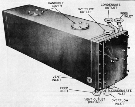
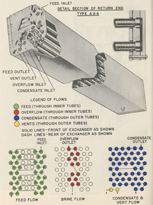
10D4. Heat exchanger. A double pipe heat exchanger (see Figure 10-14) is connected to the
evaporator (see Figure 10-12). The function of
the heat exchanger is to preheat the incoming feed
water, cool the brine overflow and condensate, and
condense any vented steam.
The heat exchanger consists of fifty 1 1/4-inch
i.d. tubes, arranged in seven rows of six tubes
across, with two rows of four tubes, one at the
center and one at the bottom. Inside each 1 1/4-inch i.d. tube is one 3/4-inch o.d. externally finned
or wired tube. The condensate flows inside forty-eight of the 1 1/4-inch i. d. tubes in series, entering
hot at the bottom and emerging cool from the top.
Steam and noncondensable gases from the steam
chest vent flow inside the two remaining 1 1/4-inch
i.d. tubes where the steam is condensed and the
gases cooled.
The heat exchanger is divided in such a way
that sea water feed flows in series through the
3/4-inch o.d. tubes inside 36 of the 1 1/4-inch i.d.
78
Figure 10-7. Immersion heater.
tubes, and brine overflow passes in series through
the 3/4-inch o.d. tubes inside 14 of the 1 1/4-inch
i.d. tubes.
The cold sea water feed enters at the top of the
exchanger and after being heated by flowing
through 36 of the inner tubes in series, flows from
the exchanger to the evaporator (see Figure 1014).
The hot brine overflow enters the heat exchanger
at the bottom and is cooled by flowing through 14
of the inner tubes in series, then leaves the heat
exchanger at the top (see Figure 10-14).
The hot condensate from the evaporator enters
the heat exchanger at the bottom and flows in
series through the annular spaces between 48 of
the inner and outer tubes as noted previously.
During this circuit, it is alternately cooled by the
incoming feed and heated by the brine overflow.
Figure 10-8. Equipment for evaporator pressure
control.
The heat picked up from the brine is transferred
again to the feed, and the condensate flows from
the top of the exchanger after being cooled to
within about 30 degrees F. of the feed temperature.
This arrangement of flows makes it possible to
have the sea water feed and the brine overflow
inside the small tubes where any scale which forms
can be removed easily.
The heat exchanger is insulated by vermiculite
enclosed by a light metal shell.
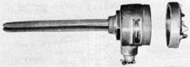
10D5. Electric heaters (Figure 10-7). The three
2,000-watt electric heaters (see Figure 10-13) are
located horizontally and parallel to each other in
the boiler section. They are special Chromalox
heaters of the tubular hairpin immersion type
with the heater section of tubing formed to a triangular shape. The immersed length is 9 1/2
inches. The heaters are used on starting the plant
to heat the initial cold feed to boiling and to generate the initial steam for compression. During
operation the electric heaters supply additional
Figure 10-9. Flow-control valve.
79
338450 O-55-7
heat so that a sufficiently high overflow rate can
be maintained to retard the formation of scale and
balance the heat losses. Proper inside operating
pressure, indicated by the compound indicating
pressure gage, is held by the automatic control of
these heaters which are turned on and off by a
pressure operated switch set to within the operating pressure limits of the plant.
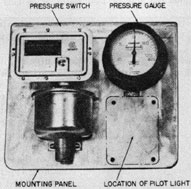
10D6. Pressure controlled switch (Figure 10-8).
The pressure controlled switch is essentially a
pressure type contact maker, set to, break the circuit to the electric heater at a pressure of 12 inches
of water, and make the circuit at a pressure of
6 inches of water. Attachment is on the mounting
plate next to the compound indicating pressure
gage. The mounting plate is located near the top
of the evaporator (see Figure 10-13).
10D7. Compound indicating pressure gage. The
dial of the compound indicating pressure gage is
graduated to indicate zero to 120 inches of water
for pressure, and zero to 15 inches of mercury for
vacuum. (See Figure 10-8.)
10D8. Compressor discharge pressure gage. The
graduations of the compressor discharge pressure
gage are zero to 15 pounds per square inch.
Mounting is on top of the evaporator beside the
compressor discharge relief valve. (See Figure
10-5.
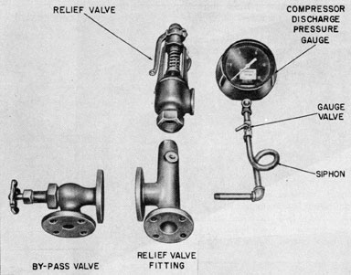
10D9. Compressor discharge relief valve. The
compressor discharge relief valve is set to relieve
at 7 1/2 pounds gage pressure. (See Figure 10-5.)
10D10. Bypass, valve. The 1-inch bypass valve
(V2) which is mounted on top of the evaporator
is connected to the 3-inch i.d. pipe on the pressure
side of the compressor, and discharges into the
vapor separator on the suction side of the compressor. (See Figure 10-5.)
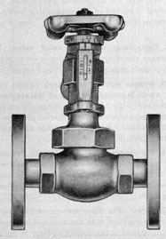
10D11. Flow-control valve. The 1/2-inch flow-control
valve is provided to control the flow of salt water
feed to the distilling unit. The valve is located
between the feed rotameter and the water regulating valve. (See Figure 10-9.)
10D12. Filter. The filter screens on the two 3/4-inch filters supplied with the unit will be removed
and will be used in the duplex strainer in the feed
water line.
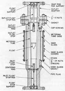
10D13. Brine rotameter. The brine rotameter
measures the flow of brine in gallons per hour.
Figure 10-10. Rotameter.
(See Figure 10-10.) Calibrated capacity=105
gph.
10D14. Feed rotameter. The feed rotameter
measures the flow of feed water in gallons per
hour. (See Figure 10-10.) Calibrated capacity=105 gph. Both the feed and brine rotameters
are the armored type.
10D15. Water regulating valve. The water regulating valve which keeps the feed flow through
the rotameter to the distilling unit at a constant
rate is located between the feed rotameter and the
filters. (See Figure 10-11.)
10D16. Sight feed valve. A 1/4-inch sight feed
valve (V3) is located on the desuperheater line to
enable the operator to observe the flow of water
to the compressor. This line is tapped to the distillate drawoff line just as it leaves the evaporator
and provides the water needed for desuperheating
purposes.
E. SOLOSHELL TWO EFFECT DISTILLING PLANT
10E1. Introduction. With the application of nuclear power to submarine propulsion there has
been installed the first steam evaporator in submarine distilling systems, the Soloshell, double
effect, low pressure distilling plant. The principles of operation of this and other types of steam
distilling plants can be found in Naval Machinery
Part III. The discussion herein will be confined
solely to the type to be found on submarines with
nuclear steam plants.
The principle of operation of the Soloshell is
not unlike that of the vapor compression type of
distilling plant. Sea water is heated to the point
of vaporization, condensed to make fresh water
and the resulting brine pumped overboard. The
heat source of the vapor compressor is electricity
whereas the heat source of the Soloshell is steam.
10E2. General. This distilling plant is of the
low pressure, two effect, Soloshell type.
The rated capacity of the two-effect unit is 4,000
gallons per clay of condensate, and the overload,
clean tube capacity, is 5,200 gallons per day with
the chlorine content of the condensate not exceeding one-fourth grain per gallon (produced
from sea water). The first effect steam will be at
a pressure not exceeding 5-psi gage and the distilling condenser at a vacuum of 26" Hg, the
density of the brine overboard discharge not exceeding one and one-half thirty seconds.
The two effect unit consists of a horizontal rectangular shell, within which are incorporated the
evaporating units, vapor feed heater, distilling
condenser, vapor separators, and water level controllers. A vertical longitudinal wall divides this
single shell into first and second effect evaporator
shells. The first effect shell contains the first
effect evaporator tube nest, vapor separator and
vapor feed heater; the second effect shell contains
the second effect evaporator tube nest, vapor separator and distilling condenser.
10E3. Principles of operation. For the purpose
of explaining the operation of the Soloshell, the
distilling plant is divided into seven different
circulating systems as follows:
1. Distiller condenser circulating water circuit.
2. Evaporator feed water circuit.
3. Vapor circuit.
4. Fresh water circuit.
5. Brine circuit.
6. Primary steam circuit.
7. Air removal circuit.
To fully understand the operation of the Soloshell and become familiar with the terminology of
the various units, the circuits should be followed
on the diagrammatic sketch as the text below is
read. (See Figure 10-15.)
1. Distiller condenser circulating water circuit.
The distiller condenser circulating water pump
takes a suction from sea and discharges through
the condensate cooler and the distilling condenser.
A strainer is provided in the pump suction piping.
The cooling water makes one pass through the
tubes of the condensate cooler and four passes
through the tubes of the distiller condenser. The
cooling water is then discharged overboard
through an orifice which is designed to maintain
8 pounds per square inch back pressure on the
distiller condenser tubes and heads.
2. Evaporator feed water circuit. The feed
water for the evaporator is taken from the distiller condenser circulating water overboard. The
orifice installed in the circulating water discharge
line (1 above) maintains a minimum back pressure on the evaporator feed line and forces
83
the evaporator feed through a pressure
reducing valve. This valve is provided in the feed
line to reduce the high pressure in the circulating
water line, which would be encountered under
submerged conditions, to a low pressure suitable to
the design of the evaporator shell. The feed then
passes through the feed heating section of the
distilling condenser, and in series, through the air
ejector condenser, the flowrator, first effect vapor
feed heater, and into the first effect evaporator
shell.
The pressure differential between the first and
second effect shell permits the second effect feed
to be discharged from the first effect shell, through
an internal fixed weir-type level control into the
second effect shell. Brine is continuously discharged overboard from the second effect evaporator shell through the internal fixed weir-type
level controller by the brine discharge pump.
It will be noted that the system is arranged so
that the feed water passes from-one heater to the
next in the order of the temperature levels in the
various units, i.e. the heating medium for the
feed heating section of the distiller condenser is
the vapor produced in the second effect evaporator
which is at a lower temperature than the heating
medium for the first effect vapor feed heater, etc.
The only exception to this order of heating is
that the air ejector condenser is placed early in
the series in order that a substantial temperature
difference will exist between the condensing steam
and the feed water, so that the size of this unit can
be reasonably small.
In well designed plants, the evaporator feed
water is heated to within about 10 degrees F. of the temperature in the first effect evaporator shell by the
series of feed heaters provided for the distilling
plant installation. After passing through the
last feed heater in the series, the feed water is
discharged to the first effect evaporator shell.
3. Vapor circuit. The vapor formed in the first
effect passes through a vapor separator to remove
any entrained moisture carried, over, and then to
a vapor feed heater. Here it gives up some of its
latent heat to the feed water going to the first
effect shell. The remaining vapor passes into the
second effect tube nest where it condenses causing
the brine in the second effect to boil.
During the evaporating process, the vapor is
disengaged from the brine at the water surface
and, although the vapor itself is pure, small particles of raw, unevaporated feed water are entrained by, and carried over with, the vapor. The
inclusion of these particles of feed water in the
vapor generated is known as "priming," or "carry
over." These particles of feed water are removed
from the vapor by vapor separators of the hook
baffle type. They have large vapor areas, and are
bolted directly over the vapor inlet connections to
the vapor feed heater and distilling condenser.
The vapor is forced to change its direction of
motion several times in passing around the edges
of the baffles or vanes at high velocity. The particles of entrained moisture are entrapped and removed by the hooked shape edges of the baffles.
All moisture collecting hooks and baffles are inclined to provide for satisfactory drainage.
Drainpipes leading below the surface of the
water are provided for discharging the separated
moisture as far away as possible from the tube
nest in the evaporator shell.
After passing through the vapor separator on
its way to the second effect tube nest, the vapor
generated in the first effect passes through the
first effect vapor feed water heater, where part
of the vapor is condensed giving up its latent heat
of vaporization to the feed water passing through
the tubes of the heater. Vapor feed heaters are
shell-and-tube type heat exchangers.
4. Fresh water circuit. The condensate formed
by the condensation of the first effect vapor in the
second effect tube nest is combined with the condensate from the distiller condenser. This combined total of the condensed vapors is routed
through a shell-and-tube type heat exchanger
called a condensate cooler, where some of the heat
remaining in the condensate is transferred to the
circulating water on its way to the distiller condenser. By virtue of the different pressures (and
boiling points) within the second effect coils and
the distiller, the drain from the two are led to a
flash chamber. When the second effect drains
reach the lower pressure of the flash chamber,
part of the hot water will flash into steam and be
vented into the distiller condenser where it is
finally condensed. A float controlled drain regulator is provided in the second effect drain to maintain a water seal. The distiller condensate pump
(a centrifugal type) takes suction from the flash
chamber, raises the pressure of the condensate to
a few pounds above atmospheric pressure, discharges to the condensate cooler and delivers it
to a solenoid valve. The solenoid valve is so wired
that flow can be directed to the ship's tanks only
when the solenoid is energized. An increase in
salinity to more than 0.25 grains per gallon de-energizes the solenoid and thus trips the valve to
the bilge. This arrangement makes it impossible
to reset the valve to discharge to the ship's tanks
until the salinity is below 0.25 grains per gallon
and the solenoid is again energized. In the event
of a power failure at the panel, the valve will trip
and discharge to the bilge.
5. Brine circuit. Fixed weir-type level controllers are installed in each shell. These consist of
a weir pipe, open at the top, connected to a weir
well at the bottom of the shell. All of the feed
water in excess of that which is evaporated spills
over the weir pipe and into the weir well and out
of the shell. After being partially evaporated in
the first effect evaporator shell, the density or
salinity of the feed water is increased and it is then
referred to as brine to distinguish it from sea water. When sufficient room is not available beneath
the distilling plant for the full loop seal, as is the
case in submarine installations, a short loop is installed with a valve for controlling the flow. In
order to insure proper operation of these overflow
weirs in the absence of a full loop seal, a water level
must be maintained in the gage glass on the first
effect weir well. This is accomplished by hand
regulating the valve between the first effect weir
well and the second effect shell. Although this
procedure still involves some hand regulation, control is much easier because a level anywhere in
the gage glass is satisfactory. Also, once the
proper valve setting has been obtained with the
plant operating at full capacity, it may be left
in that position and not disturbed when starting
or securing the plant.
It is not necessary to maintain a water level
in the weir well between the second effect shell
and the brine pump. This level may be anywhere
in the glass or out of sight below it. However
when the gage glass becomes completely flooded,
a stoppage or reduction in flow of brine overboard
due to improper operation of the brine pump or
other difficulty is indicated. When the overflow
weir-type level controls are provided no attempt
should be made to regulate the brine pump discharge
valve. This valve is left in a fixed open
position so that the pump is able to discharge
whatever amount of brine overflows the second
effect weir pipe. In order to increase the flow
of brine overboard and thus reduce the brine density it is merely necessary to increase the flow of
feed to the first effect evaporator.
On submarine installations there are two brine
pumps provided; a low pressure pump capable
of discharging the brine overboard when operating
the plant while surfaced or at depths down to
periscope depth, and a high pressure pump which
is used in series with the low pressure pump when
operating the plant at depths below periscope
depth.
When operating the low pressure pump alone,
the discharge is led to the engine room circulating
water discharge line. When operating the high
pressure pump in series with the low pressure
pump, the discharge of the low pressure pump is
directed to a brine collecting tank in which there
is a ball float. The ball float operates a valve in
the discharge line of the high pressure pump.
Thus when the water level in the brine collecting
tank has reached a predetermined height the
discharge valve of the high pressure pump is
opened and the high pressure pump then takes a
suction on the tank and the discharge line of
the low pressure pump. It is evident then, that
the ball float operated high pressure pump discharge valve prevents the high pressure pump
from taking a suction on the low pressure pump
discharge line which would exceed the gallon
per minute discharge rate of the low pressure
pump.
The first and second effect shell drains are also
connected to the low pressure brine pump through
stop valves.
6. Primary steam circuit. Main steam is supplied to the first effect evaporator tubes through
a spring loaded, 5-psi reducer. An orifice plate
is installed below this valve to permit operating
with steam in the tubes at a pressure below atmospheric. The thermometer in the steam line between the orifice and the first effect evaporator
tube nest will usually indicate superheat, due to
the initial condition of the main steam and the
throttling action through the reducing valve and
the orifice. As this temperature might be too high,
resulting in scale formation, the steam temperature
85
is lowered to the saturation temperature by
means of a desuperheating spray line through
which condensate is brought back from the discharge side of the engineroom condensate removal
system and is sprayed into the incoming steam,
removing any superheat present. The condensed
main steam, called "first effect drain" is drained
to the engineroom condensate collecting system,
which is operating under a vacuum. A float controlled drain regulator is provided in the drain
line to maintain a water seal. It should be borne
in mind that the main steam is the immediate
source of all the heat used by the entire plant with
the exception of the heat absorbed from the air
ejector jet steam.
7. Air removal circuit. Air and noncondensable
vapors enter the plant mainly with the evaporator
feed water in which they are dissolved. As the
feed water is heated, the dissolved air is freed
and tends to collect in various units of the plant.
Air also enters the plant with the incoming steam
and through various small leaks at pump glands
and imperfect joints. Since the distilling condenser is at the lower end of the heat flow cycle of
the distilling plant, the absolute pressure within
this unit is lower than that within any other unit
of the plant and all air and noncondensable gases,
which leak into the system, tend to collect in the
condenser. In order that the required vacuum
may be maintained, the noncondensable gases must
be removed so that they will not insulate the condensing tubes and render the cooling surfaces
ineffective.
Air enters the distiller condenser with vapor
from the second effect evaporator and flash chamber as well as through a series of vent lines which
are led from various units of the plant to the
distiller condenser. The proper functioning of
these vents is essential to the satisfactory operation of the plant. Two single stage air ejectors
having an after condenser common to both are
provided for removing the noncondensable vapors
and air which accumulate in the distilling condenser. Either of these ejectors is capable of
removing the air from the plant under normal
conditions of air leakage, the second ejector being
available as a spare or for use under abnormal
conditions of air leakage.
The air ejector suction piping is connected to
the air precooling section of the distilling condenser.
The main function of the air precooler
is to cool and remove all possible water vapor
from the air to be handled by the ejectors, thereby
reducing the total volume of the gas as much as
practicable.
The motive steam is supplied to the air ejectors
from the main steam line through a reducing valve
which reduces the pressure to about 150 psi.
The steam jet issuing from the nozzle of the
air ejector entrains the air and noncondensable
vapors from the distiller condenser and raises the
pressure of the mixture lightly above atmospheric.
This steam is condensed and the air is cooled in
the air ejector condenser where the vapor gives up
its latent heat to the evaporator feed water passing through the condensing tubes of this unit. The
air and noncondensable vapors are vented to the
atmosphere. The condensate is returned to the
engineroom condensate removal system.
10E4. Starting and securing.
STARTING
1. Open wide all valves in the circulating water
circuit from the sea suction to the overboard
discharge.
2. Start the circulating pump.
3. Open all air vent cocks on the distilling condenser, vapor feed heater, and air ejector condenser heads until the air is expelled, then shut them.
4. Open the feed valves until the tube nests are
fully covered, regulate the second feed valve to
maintain the proper water level in the first effect
shell.
5. Open the necessary valves in the brine overboard discharge system and start the low pressure
brine discharge pump. If below periscope depth,
the low pressure pump must be used in series with
the high pressure brine discharge pump.
6. Open the second effect evaporator tube nest
vent valves wide. The first effect tube nest vent
valve should remain shut.
7. Insure that the first effect tube nest and air
ejector condenser drain valves to the bilge are
open, and that the valves in these drain lines to
the ship's condensate return system are shut.
8. Open-air suction to the ejector. Open supply
steam to the ejector, insuring that full pressure
required (stamped on nameplate) is available at
the nozzle, and that steam supply is properly
drained.
9. Test the salinity of the air ejector condenser
86
drain. When less than 0.25 grains per gallon,
shut bilge drain and open drain to tank.
10. When second effect shell vacuum is about
16 inches, open first effect tube nest steam supply
valve wide. Adjust regulating valve to maintain
steam pressure of, about 5 psi above the orifice.
Last effect shell vacuum should continue to increase to 26 inches or more.
11. When condensate discharges from the first
effect drain line to the bilge, test for salinity.
When satisfactory, shut the bilge discharge line
and open valves as necessary to discharge the condensate to the return system and open the first
effect tube nest vent valve one full turn.
12. When condensate appears in the second effect drainer, see that drainer discharge valve
is open, and adjust second effect tube nest vent
valve to the operating position (approximately
one turn open).
13. When condensate appears in the flash chamber or distilling condenser hot well, make sure the
condensate cooler discharge is directed to the bilge
by manually tripping the solenoid actuated valve.
Then start the condensate pump.
14. Regulate the first effect feed valve so as to
obtain a rate of feed flow of approximately three
times the normal distilling plant output. Open
the second effect feed valve so as to maintain a
level in the first effect weir well gage glass.
15. When the salinity of the condensate leaving
the condensate cooler is less than 0.25 grains/gallon, set the solenoid valve to discharge to the
ship's tanks.
16. Open and adjust feed treatment injection
valve if feed treatment is to be practiced.
17. When the plant has been in full operation
for 15 to 20 minutes, determine the rate of distilled
water production by means of the meter in the
condensate cooler discharge line. The rate of production may be increased or decreased through
a small range by increasing the steam pressure
above the orifice.
18. When the desired rate of output has been
set, determine the density of the evaporator feed,
then adjust the evaporator feed valve to obtain
a rate of flow in accordance with the table below.
The rate of feed flow will be indicated by the
flowrator in the feed line.
Feed Density (32nds)
1/2
3/4
1
1 1/8
1 1/4
Ratio of Feed to Fresh Water Output
1.5
2
3
4
6
19. After the plant has been in operation about
an hour, and occasionally thereafter, check the
density of the brine pump discharge, and adjust
the first effect feed valve as necessary to maintain
a brine density of 1 1/2 thirty-seconds. The brine
density is reduced by increasing the rate of feed,
and increased by reducing the rate of feed.
10E5. Securing.
1. Shut steam supply to first effect tube nest.
2. Shut the first effect tube nest drain to return
system and open drains to bilge.
3. Shut first effect tube nest vent valve.
4. Shut air suction and steam supply valves to
air ejector.
5. Open second effect tube nest vent valve wide.
6. Secure the condensate pump.
7. Continue operation of circulating water and
brine overboard discharge pumps for 10 minutes
or longer to cool all parts of the distilling plant.
8. Secure the brine overboard pump.
9. When both tube nests are fully covered with
water, secure the circulating pump.
10. Shut feed valve to the first effect and to the
second effect.
11. Shut the suction and overboard sea chests.
12. Shut air ejector and condenser drain lines
to return system and open drains to bilge.
13. Trip the solenoid actuated valve to discharge to the bilge.
10E6. General notes.
1. Pumps must not be run dry. Before starting
any pump, make certain that the suction, vent,
and gland seal valves are open, and that the pump
casing is full of water. On centrifugal pumps,
it is preferable to leave the discharge valve closed
until after the pump has been started.
2. It is permissible to run a centrifugal pump
with the discharge valve shut for periods of 15
to 20 minutes.
10E7. Feed and brine density. The salt content
of sea water is measured in thirty-seconds, and is
called its density. Thus, sea water is said to have
a density of 1/32 if a 32-pound sample contains 1
pound of salts. Sea water feed is partially boiled
off in the distilling plant, and the remaining brine
which is discharged overboard has a higher "density" than the initial feed. For best results, the
brine density must be held constant at 1 1/2 thirty-seconds. A higher density will result in more
scale throughout the plant, while a lower density
87
results in a needless waste of heat because of the
unnecessarily large amount of brine discharged
overboard. The brine (or feed) density is measured by salinometers which are calibrated to read
directly in thirty-seconds. Salinometers are not
to be confused with electrical salinity indicators
which measure the salt content of the distillate.
A suitable salinometer must be available for
each distilling plant. It should be calibrated for
temperatures of 110 degrees, 115 degrees, 120 degrees, and 125 degrees F. If
the salinometer is misplaced or lost, a new one
should be procured immediately.
With the overflow weir-type level controllers
the brine density is maintained at the appropriate
value of 1 1/2 thirty-seconds by regulating the feed
valve to the first effect evaporator.
No attempt should be made to regulate the brine
pump discharge valve. This valve is left in a
fixed open position so that the pump is able to
discharge whatever amount of brine overflows the
second effect weir pipe. In order to increase the
flow of brine overboard, and thus reduce the brine
density, it is merely necessary to increase the flow
of feed to the first effect evaporator.
Samples of brine are usually obtained through
a sampling cock at the brine pump discharge. It
is important to obtain a sample truly representative of the brine in the last effect shell. The temperature of the sample drawn into the sampling
pot should agree closely with the reading of the
thermometer on the last effect shell. A difference
of more than 3 degrees or 4 degrees usually indicates faulty
operation of the brine pump, or dilution of the
brine between the last effect shell and the sampling
cock.
If the pump gland is located on the same side
of the pump casing as the pump inlet, the brine
may be diluted by sealing water. In such cases it
may be possible to obtain a correct sample by
closing the valve in the gland sealing line temporarily. Some installations have been made
with a brine diluting line connected from the
circulating pump discharge to the brine pump suction to improve the operation of the pump. This
line is not necessary, and, unless the flow through
it is very carefully adjusted, the flow of brine
from the last effect shell to the brine pump may
be stopped altogether.
A true sample can always be obtained by means
of a vacuum test pot connected to the last effect
shell. Such a sampling pot is not as convenient
as a petcock at the brine pump discharge, but is
recommended where the danger of dilution exists
because of the type of pump used, because of the
presence of a brine diluting line, or because drain
lines from other effects (besides the last) are connected to the brine pump.
The amount of brine which must be discharged
overboard in order to maintain a constant last
effect shell density of 1 1/2 thirty-seconds varies
through a wide range, depending on the density
of the initial feed. Feed density is not constant.
It varies from less than 1 to more than 1.2 thirty-seconds in open oceans, and through an even
greater range when inland seas (such as the Red
Sea) and sheltered bays are considered. The
higher values are usually found in tropical waters,
and the lower values in northern waters.
The amount of brine to be discharged overboard
for each pound of distillate is given by the following term:
(f) / (1.5-f)
where f is initial feed density in thirty-seconds.
Thus for an initial density of 1 thirty-seconds,
two pounds of brine must be discharged overboard
for every pound of distillate; for an initial density
of 1 1/4 thirty-seconds, five pounds must be discharged, etc. It is evident, therefore, that a fixed
quantity of feed water will not result in a constant
brine density of 1 1/2 thirty-seconds in the last effect
shell. It is essential that the brine density be
checked at hourly intervals, and that the brine
regulating feed control valve be adjusted as necessary. The amount of feed required in order to
maintain a brine density of 1 1/2 thirty-seconds in
the last effect is given by the following expression:.
(1.5) / (1.5-f) X distillate in gal/min
where f again is the initial feed density in thirty-seconds. Since rotameters are usually calibrated
in gallons per minute, the distillate must also be
in gallons per minute. Thus for a plant producing 10 gals/min of distillate, feed flow required
when the initial density is 1 thirty-seconds is 30
gals/min; feed flow required when the initial density is 1 1/4 thirty-seconds is 60 gals/min, etc.
Feed samples for density test may be obtained
from the vent or drain connections on the distilling
88
condenser or air ejector condenser heads
at a temperature within the range of the
salinometer.
When using a flowrator to regulate the feed rate,
brine samples should be obtained and the density
checked by the salinometer at regular intervals
to prevent possibility of excessive density because
of incorrect readings of the flowmeter.
10E8. Scale. The character and amount of scale
deposited on the tube surfaces will depend not
only upon proper operation in accordance with
the manufacturer's instructions, but also upon the
quality of the feed water. In low pressure distilling plants, scale results primarily from calcium
carbonate and other minor constituents of sea
water. The ratio of these minor constituents to
the total solids in sea water is not always the same.
Hence, it does not follow that two waters having
the same density (same total solids) will necessarily result in the same amount of scale under
the same operating conditions. Some bay and
harbor waters of very low density may result in
far more scale than ocean water. In the oceans,
more scale should be expected near coral islands
than in other regions even though the feed density
may be the same. In open waters, away from the
effects of fresh water rivers, coral islands, etc. the
feed density is an index of scale forming properties. Scale deposits may be reduced by proper
feed treatment. This subject will be taken up
later in the text.
When no feed treatment is used, a relatively
brittle scale is usually formed. This can be partially removed by chill-shocking the plant daily,
thus prolonging the period between shutdowns
for cleaning. If the plant is usually secured a
part of each day, no other chill-shocking is necessary as the scale will automatically crack off when
the plant is started up again. When feed treatment is used, the deposit builds up very slowly,
and does not crack as readily as untreated scale.
Daily chill-shocking may be beneficial, but a
longer interval may be entirely satisfactory. The
optimum chill-shocking period must be determined
from experience.
10E9. Chill-shocking. Most distilling plants are
provided with special flushing pipes over the
evaporator tubes to facilitate chill-shocking. The
procedure is as follows:
1. Secure the following: Steam supply to the
air ejector, the air ejector condenser drain line,
the steam supply to the first effect tube nest, the
first effect tube nest drain line to the condenser,
the feed valve to the first effect, the condensate
pump and the brine pump.
2. Open the drain on the bottom of each shell
and pump the shells. Shut the drain valves.
3. Open the water supply valve to the internal
spray pipes and allow all evaporator tubes to
become fully submerged.
4. Shut the water supply to the spray pipes and
repeat step number 2.
5. Repeat step number 3. When the tubes are
fully submerged, secure the water to the spray
pipes, and quickly open the steam valve to the
first effect tube nest. The flow of steam will be
restricted by the orifice but may be increased for
more effective "shocking" by increasing the pressure above the orifice. After the plant has been
warmed up, this pressure should be brought back
to normal.
6. To put the plant back in operation open the
first effect tube nest drain valve to the condenser,
supply steam to the air ejectors, open the air
ejector condenser drain valve to the drain system,
open the feed valve to the first effect and start
the brine and condensate pumps.
10E10. Feed treatment. Vacuum type distilling
plants can be operated for relatively long periods
of time without overhaul and without feed treatment, if properly handled. However, it has been
determined that the continuous injection of feed
treatment into the first effect shell reduces the
deposit on the evaporator tubes and in the brine
lines.
Instructions for mixing and injecting a feed
treatment mixture can be found in the manufacturer's instruction books.
10E11. Purity of condensate. It is very important
that only pure condensate be sent to the ship's
fresh water or reserve feed tanks. All distillate
having a salt content in excess of a predetermined
maximum (usually 0.25 grains per gallon) must
be discharged to the bilge. In the case of submarine installations this is done automatically by
the solenoid dump valve located on the discharge
side of the condensate cooler. The manufacturer's
instruction books should be consulted to aid in
locating the source of excessive salinity.
89
10E12. Operation with contaminated feed water.
When operating in regions where the feed water
may be contaminated with bacteria, such as in or
near rivers, harbors, sheltered bays, etc., it is of
the utmost importance to send only distillate of
known purity to the ship's tanks as the health of
the entire crew depends upon the production of
sterile water. It has been determined that sterile
distillate may be obtained without increasing the
pressures and temperatures, providing the total
impurities do not exceed 0.25 grains per gallon.
This phenomenon occurs naturally when the sun's
rays evaporate water free of bacteria at atmospheric temperatures and at low evaporation rates.
Evaporation of water, either at atmospheric
pressure or at reduced pressures and temperatures,
is a physical separation of water from its dissolved
and suspended constituents. Bacteria are larger
particles than molecules of salt, and therefore, are
also left behind in the brine. The sterilization of
water by subjection to high temperature is not
necessary if contamination of the distillate by
priming or salt water leakage is prevented.
The salinity of the distillate may be watched
as an index of such priming or leakage and the
discarding of all condensate having a saline content of more than 0.25 grains per gallon will protect the men. The solenoid valve for automatically
dumping the distillate to the bilge whenever the
salinity exceeds the maximum gives added protection. The distillate should also be tested
chemically at frequent intervals in order to check
the electrical indicator.
The U.S. Public Health Service stresses the
importance of not operating the distilling plant
in contaminated harbors because of the possibility
of contamination of the distillate by distillation
of oil or other volatile substances in the feed
water. The U.S. Public Health Service further
advises against operation of the plant in brackish
or fresh contaminated water as the salinity indicator and solenoid valve are of little value in protecting the system against improper operation and
carryover of impurities in the feed.
10E13. Materials. The evaporator division wall,
shell, shell covers, tube sheets and tube nest covers
of all units, evaporator tube support plates and
all tubes are copper nickel alloy. All other tube
support plates and vapor separators are naval
rolled brass. Drain regulator bodies are gun
metal. Replaceable zincs are provided in all salt
water heads.
The evaporator tube bundles consist of 5/8-inch
o.d. U-tubes, 0.049-inch wall thickness, expanded
at both ends into a tube sheet and supported by a
support plate. One tube sheet is bolted to the
front of the shell so that the tube nest is free to
expand. Support plates are supported on rails
in the shell so that the tube nest is free to expand.
The U-tubes are arranged for two passes of the
heating steam. The air vents to the second effect
shell are taken from the second pass compartment
in the tube nest cover through a perforated baffle.
Sight glasses are fitted in the front of each evaporator shell for observing the operating condition
within. Perforated spray pipes are fitted over the
first and second effect tube nests for chill-shocking
purposes and are externally connected through the
front of the shell.
The vapor feed heater is of the straight tube
type, having 5/8-inch o.d., 0.049-inch thick tubes
expanded into a tube sheet at each end. Expansion of the tubes is permitted through the use of
a floating head resting on guides in the vapor
feed heater chamber.
The distilling condenser consists of two tube
bundles, one being the condensing section, consisting of U-tubes; the other a feed heating section,
consisting of straight tubes. The condensing section is of the U-tube type having 5/8-inch o.d.,
0.065-inch thick tubes expanded at both ends into
a tube sheet. A tube support plate supports the
U-tube bundle. The feed heating section of the
condenser is of the straight tube type, leaving
5/8-inch o.d., 0.049-inch thick tubes expanded into
a tube sheet at each end. Expansion of the tubes
is permitted through the use of a floating head
resting on guides in the vapor feed beater
chamber.
The air ejectors are of the single stage type.
The air entering the ejector from the evaporator
is entrained by the steam jet issuing from the
nozzle and is carried through the diffuser, compressed to atmospheric pressure and discharged
to the air ejector condenser where its heat is given
up to the evaporator feed water. The air ejector
condenser is of the straight tube type, having 5/8-inch o.d., 0.049 inch thick tubes expanded into a
tube sheet at each end. The cylindrical shell is
of copper, and differential thermal expansion
90
between the shell and the tubes is provided for by
the flanged ends of the shell. The air ejector
steam passes through the shell and the evaporator
feed makes several passes through the tubes. The
air is discharged to the atmosphere through two
vent pipes. The condensate drains from the
bottom of the condenser to the drain collecting
system.
The flash chamber is essentially a receptacle
within which the vapor, liberated when the second
effect drains are reduced to a pressure and temperature corresponding to the distilling condenser
vacuum, is separated from the condensate and
directed to the condenser. The total output of
the plant is collected within the flash chamber
and flows to the condensate pump. The flash
chamber is attached to the second effect side of the
evaporator shell.
The first and second effect tube nest drain regulators are of the style "F" (Griscomb-Russell) internal valve, piston type balance valve design with
ball float. The regulators may be locked open in
case of derangement. The condensate cooler is of
the straight tube type, having 5/8-inch o.d., 0.065inch thick tubes, expanded into a tube sheet at
each end.
The firmed weir-type level controllers are located
internally and are directly attached to the bottom
of the first and second effect evaporator shell. The
level controller is self-venting to its respective
evaporator shell. Water level within the evaporator is maintained by the fixed weir pipes attached to the level controller body. This water
level is indicated by gage glasses likewise fitted
to the level controller.
The flowrator is located in the feed piping, between the feed water outlet connection on the air
ejector condenser and the feed water inlet on the
first effect vapor feed heater. It is calibrated in
gallons per minute and visually indicates amount
of feed water being supplied to the plant.
The feed reducing valve is provided to reduce
the high pressures which may be encountered
under submerged conditions to a low pressure suitable to the design of the evaporator shell, heaters
and condenser bundles. For surface operation a
back pressure valve is located on the circulating
water piping overboard to maintain sufficient back
pressure to force the feed through the reducing
valve and heaters in the feed line and into the first
effect shell.