|
11A1. Position distance transmitter load
switch. The distance transmitter load switch
(Figure 11-1) is mounted in the upper right
corner of the master transmitter indicator.
This switch is set in the heavy load position
when there are more than two repeaters operating, or when the dead reckoning tracer
(DRT) and dead reckoning analyzer (DRA)
are in operation. Otherwise, it is in the light
load position at all times. This switch is used
for making a rough adjustment to vary the
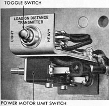
Figure 11-1. Distance transmitter load switch.
maximum torque output of the follow-up
motor. The variable rheostat is employed for
a fine adjustment of the output of the follow-up motor.
11A2. Energizing the system. Turn the electrical switches controlling the 1Y, 2Y, and 3Y
circuits on the interior communications (I.C.)
switchboard and the conning tower repeater
switch on the action cutout (A.C.O.) switchboard to their ON positions.
11A3. Opening the sea valve. Raise the deck
plate above the sea valve. Turn the sea valve
handwheel in a counterclockwise direction as
far as possible to fully open the sea valve gate.
|
|
11A4. Lowering the rodmeter. (See Figure
10-7.) The rodmeter will be in one or two
positions: the normally housed position as
shown in Figure 10-7, or the fully housed
position. To lower the rodmeter, turn the
hoist crank counterclockwise until the rodmeter is in its extended, or operating position.
Keep the hose clear of projections and chain
links.
11A5. Venting the system. Do not vent the
system when the ship is submerged. Such a
practice will damage the bellows mechanism
due to the fact that the pressure increases
approximately 1/2 pound per square foot for
each foot of submergence, and it is practically
impossible to open or close the dynamic and
static valves simultaneously so as to keep the
pressures equal on both sides of the bellows.
For best results the ship should be stationary. The purpose of venting the hydraulic
system is to remove any air that may be
trapped in the system. Vent the hydraulic
system in the following manner. Turn the
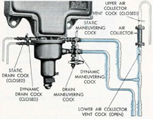
Figure 11-2. Maneuvering cocks and drain cocks
in secured position.
maneuvering cocks and drain cocks from their
secured position (Figure 11-2) to the venting
position (Figure 11-3). Keep the valves in
this position until a clear stream of water,
|
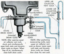
NOTE: After opening upper air collector vent cock slowly and simultaneously open both static and dynamic drain cocks as shown. When free of air, simultaneously close both drain cocks.
NOTE: After positioning maneuvering cocks, open upper air collector vent cock as shown. Leave open until static and dynamic drain cocks are closed; then close this vent cock.
Figure 11-3. Maneuvering cocks and drain cocks
in venting position.
free of spitting is obtained; then turn the
maneuvering cocks and drain cocks to their
operating positions (Figure 11-4). Turn the
maneuvering cocks first in going to, and in
going from, the venting position.
11A6. Securing the log. Whenever the ship
enters port, the log system should be secured.
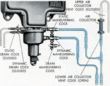
Figure 11-4. Maneuvering cocks and drain cocks
in operating position.
This is done in the following manner: Turn
the hoist crank in a clockwise direction until
the top of the rodmeter is level with the
marker plate, indicating that the tip of the
rod is clear of the hull. Keep the hose clear
of projections as the rodmeter is raised. The
rodmeter may be raised to its fully housed, or
|
|
secured, position by turning the crank until
the top of the rodmeter hits the stop at the top
of the hoist. Turn the valves to their secured
position as shown in Figure 11-2. Turn the
1Y, 2Y, and 3Y switches on the I.C. switchboard, and the conning tower switch on the
A.C.O. switchboard to their OFF positions.
11A7. Draining the hydraulic lines. If the
ship is to be in port for an extended time, or
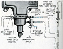
Figure 11-5. Maneuvering cocks and drain cocks
in drain position.
if it becomes necessary to make repairs on the
hydraulic lines, the fines are drained in the
following manner: Raise the rodmeter to its
fully housed, or secured, position. Position
the valves and vent cocks as shown in Figure
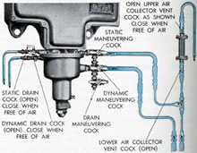
Figure 11-6. Maneuvering cocks and drain cocks
positioned for filing hydraulic lines.
|
|
11-5. With the valves in this position, the
water will drain from the lines through the
drain maneuvering cock.
11A8. Filling the hydraulic system. If the
ship is equipped with a new log installation,
or if the hydraulic system has previously been
drained, fill the hydraulic system in the following manner: Lower the rodmeter to its
|
|
extended, or operating, position. Position the
valves and vent cocks as shown in Figure 11-6.
When a full stream of water, free of spitting
is obtained from the upper air collector valve,
close this valve. Tap the bellows housing to
facilitate the removal of air from the bellows
chamber, and when a full stream of water is
obtained from the static and dynamic vent
cocks, close these drain cocks. Vent the system thoroughly as described in Section 11A5.
Turn the valves to the desired position.
|
