MAINTENANCE OF ELECTRICAL EQUIPMENT and
MEASUREMENT OF INSULATION RESISTANCE
A. MAIN MOTORS AND GENERATORS
7A1. Inspection and cleaning. Frequent inspection
and cleaning are necessary to insure
trouble-free operation and long life of motors
and generators. Machines should be examined
for cleanliness, proper lubrication, tightness of
connections, and freedom from moisture before
every start.
Inspect the commutator frequently for uniform,
hard surface gloss. Check for serious
roughness and dirtiness of the slots between segments.
Examine the brushes for wear and freedom in the brush
holders. Check the brush
holder spring tensions and see that pigtail connections
are tight. Inspect the windings for presence of dirt
and oil and clean them if necessary.
Accumulations of brush dust must be removed.
Check the bearings for adequate lubrication,
signs of wear, and condition of the journal surface;
scoring is likely to be an evidence of the
presence of foreign particles in the lubricating
oil. Joints in connections and at terminals must
be inspected to make certain they are tight.
Careful inspection must be made to insure that
there is no oil leakage into the machines. Check
to see that the joints on all covers and shields
are tightly sealed. Inspect the equipment in operation
for sparking, vibration, and temperature.
Cleanliness is one of the most important factors
in proper maintenance of motors and generators.
Keep both the interior and exterior of the
machines free from water, salt, lint, dust, dirt,
and particularly, oil.
Most of the casualties to main motors and
generators of submarines may be attributed to
lubricating oil or other foreign matter reaching
the commutator, armature, or field coils. This
gradually breaks down the insulation and finally
results in burned-out coils or armatures. The
penetrating and damaging effect of oil in electrical
apparatus is universally known and must
always be carefully guarded against. This is
especially true in the submarine service where
electrical machinery is operated under adverse
conditions, due to the continual moisture, and
the many sources from which lubricating oil may
find its way inside the machine casing.
Loose dust or foreign particles located in
accessible parts of the machine may be removed
by wiping with a clean dry cloth. Cheesecloth
is recommended for this purpose. Do not use a
cloth that deposits lint.
Compressed air is effective in removing
loose foreign matter from inaccessible locations.
Its use, however, is not recommended unless the
machine can be opened sufficiently to permit
air and dirt to escape. There is always danger
of blowing abrasive particles into insulation or
beneath insulating tapes.
The use of suction is preferable since there
is less possibility of damaging insulation.
A flexible tube attached to the suction side of a
portable blower makes a suitable vacuum cleaner
for this purpose. Grit, iron dust, and copper
particles should be removed by this method
only, whenever possible.
If the accumulation of dirt on insulation
surfaces contains grease or oil, a solvent is
usually necessary to remove it. An approved
nontoxic and nonexplosive solvent must be used
and then only sparingly. The solvent should be
applied by moistening a lintless cloth with the
fluid and lightly rubbing the surfaces to be
cleaned. Excessive use of solvent may soften
the insulation. After cleaning, the surfaces
should be dried thoroughly to remove all traces
of solvent.
CAUTION. Carbon tetrachloride is one of
the best solvents for this purpose; but it must
not be used in confined spaces and must never
be taken to sea in a submarine due to its toxic
properties. Crews of submarines have been poisoned
by its fumes.
97
7A2. Definition of insulation resistance.
When a constant potential is impressed across
insulation, the current which flows is inversely
proportional to the resistivity of the insulation.
Depending upon the physical arrangement of
the conductors and insulation, the paths
followed by the current may become somewhat
complicated. In general, however, the current
flow is through the body of the insulation or
over its surface, or through a combination of
both. The resistance opposing this flow of
current is defined as insulation resistance.
1. A direct reading ohmmeter of the hand-driven
generator type (megger).
2. The ground detector system (Sections
3A15, 3C4, and 3C5) for main propulsion motors
and generators by converting the voltmeter
readings into resistance values.
3. A voltmeter (high-resistance type) or
milliammeter and a d.c. voltage supply.
4. A resistance bridge.
5. A direct indicating ohmmeter of the
generator, battery, or electronic type.
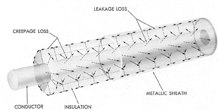
Figure 7-1. Leakage paths in cable construction.
Insulation resistance may be measured
without damage to the insulation. A
correct interpretation of such a measurement is usually
the most convenient measure of the condition
of the insulation. It can be used as a guide in
determining when cleaning, drying, or overhaul
is necessary, thereby preventing further development
of conditions which might eventually
lead to insulation failure in service. A properly
interpreted reading may also eliminate needless
shutdowns, overhauls, or renewals to improve
insulation resistance that is entirely adequate.
7A3. Methods of measuring insulation resistance.
Insulation resistance may be measured by various
instruments such as:
In the second method, the circuits to be
tested must be energized to cause a deflection.
This method, therefore, provides a convenient
means of testing for grounds and measuring
insulation resistance with no interruption in
service. Methods 1 and 2 are the most commonly
used.
If a megger is used, the circuit must be deenergized
while the instrument is used to take
readings, and the hand-driven generator should
be cranked as long as practicable to obtain a
steady reading. Subsequent tests should be made
in the same manner so that readings will be
comparable.
If the portable voltmeter method is used,
98
care should always be exercised to restrict the
applied voltage to a value commensurate with
the condition of the insulation. It should also be
noted that the resistance of the voltmeter has a
direct bearing on the accuracy of the results. A
voltmeter having a sensitivity of 100 ohms per
volt does not permit measurements in excess of
2 megohms with any degree of accuracy for an
applied voltage of 500 volts. The maximum resistance
that can be measured with voltmeters
having a sensitivity higher than 100 ohms per
volt increases in direct ratio to the sensitivity
in ohms per volt.
The instruments used in insulation resistance
testing should be well maintained and periodically
checked to insure that the rated voltage is delivered and that the instrument is in
calibration.
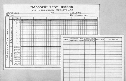
7A4. Records of insulation resistance measurements.
Suitable forms, such as the Megger
Test Record (Figure 7-2), are provided for
keeping accurate records of measured values.
When properly filled out, the forms give the
apparatus or circuit, the date, and the condition
under which the reading was taken. Any change
that may have taken place can thus be noted
by comparison with previously recorded values
on file.
7A5. Factors affecting resistance values.
The principal factors that may influence values
of insulation resistance measured in service are:
1. Connected cable and electrical apparatus. Other
apparatus connected in the circuit
may have an important bearing on observed
values. For example, when measurements are
taken on a generator connected to a switchboard,
the value obtained includes not only the
resistance of the generator circuits but also that
of the bus work of the switchboard, all apparatus
connected to the bus, and the generator cables.
Since the insulation resistance of all this equipment
is in parallel, the measured value may be
quite low, but no conclusion as to the condition
of the generator may be drawn from the value
obtained. The reading indicates merely that the
Figure 7-2. Megger test record card.
99
insulation resistance of the circuit, as a whole,
is low.
For preliminary significant measurements,
the machine should be isolated only to the
extent of opening line switches, circuit breakers,
and conductors. The insulation resistance measurement
taken in this manner will still include
the effect of connected cables and equipment
that cannot be conveniently disconnected. For
this reason, further isolation must be undertaken
if precise readings of the apparatus in question
are to be obtained. Armature windings, for example,
may be further isolated by lifting all
brushes off the commutator; shunt field circuits
may be broken up by disconnecting the leads
connecting successive poles; and cables may be
isolated by completely disconnecting the cable
at both ends. The degree of isolation must be
progressive if it is to determine accurately the
weak spots. As more isolation is undertaken,
higher resistance values should be expected
within the component part of the circuit involved,
because of the reduction of possible
parallel current paths to ground.
NOTE. Before proceeding with complete
isolation, corrective measures, such as
elimination of excessive moisture in the
insulation, condensation on its surfaces,
and removal of accumulated foreign matter, should be undertaken.
Tests may then show sufficient improvement in
the insulation resistance to eliminate the
necessity of breaking the internal connection within
the machine.
2. Moisture. Moisture content has a significant
effect on insulation resistance and must
be taken into account. All insulating materials
absorb moisture from the atmosphere, some
more readily than others. For example, cotton,
paper, and asbestos insulation materials absorb
moisture more readily than does mica. Vacuum
pressure impregnated insulation keeps out moisture
more effectively than built-up or immersion
impregnated insulation. Insulation that has
cracked or is otherwise damaged usually is more
susceptible to moisture absorption, other
conditions being equal.
Normally the moisture may be driven off
or evaporated by the application of heat. Heat
may be applied internally by the passage of
current through the conductors or externally
by heaters used to raise the temperature in the
affected area. If, however, in addition to
moisture, the insulation has deteriorated
from exposure to oil, acid, or other harmful matter,
the insulation resistance probably cannot be
restored to its original value.
3. Temperature. The resistance of any
insulating material varies with temperature. The
resistance of copper and other common con
ducting materials increases with temperature
rise, the resistance of insulation decreases as the
temperature rises. The presence of moisture in
the insulation also greatly affects the values of
insulation resistance at different temperatures.
Temperature must always be taken into consideration
when observed values of insulation resistance
are being interpreted. When readings
are taken at intervals, the values may be
properly compared only when taken at approximately
the same temperature or when due allowance is made
for differences in temperature.
Similarly, readings taken at room temperature
must be compared only with previous, readings
under the same conditions of humidity.
4. Cleanliness. The condition of the insulation
influences the value of insulation resistance.
Foreign matter such as dust, salt, carbon,
or copper dust form conducting paths. The
presence of oil or moisture acts as a binding agent
and encourages the accumulation of such foreign
matter, increasing the conductivity of the
paths. The windings of rotating electrical
machinery particularly collect such deposits in
service. Other factors remaining constant, the
relative variations in insulation resistance over
a period of time are an indication of the degree
of cleanliness of the insulation. A winding that
may be in good condition in all other respects
may have a low insulation resistance caused
solely by deposits of foreign matter. After a
thorough cleaning, the value may increase to
an acceptable amount.
5. Condition of insulation. Any insulating
material deteriorates with age, due to the
individual or combined effects of heat, moisture,
vibration, mechanical injuries, oxidation,
and chemical action from acid or alkali fumes,
salt, air, oil, and so forth. The rate of deterioration
100
depends upon the conditions to which the
insulation is exposed, such as location, type of
service, atmosphere, and the amount of care.
Although deterioration is inevitable, the life of
the insulation may be lengthened appreciably
by constant intelligent maintenance suited to
the service conditions imposed.
6. Residual charges. Residual charges of
static electricity, if present in a winding, affect
insulation resistance measurements and should
therefore be removed by grounding the conductors
for a few minutes before measurements are
made.
7. Construction. In the case of rotating
electrical machinery, the dimensions, shape,
number of turns, type of insulation, and process
of manufacture influence the insulation resistance
of the windings of machines. Windings in
large or low-voltage machines will have inherently
lower insulation resistances than those in
small or high-voltage machines. Field windings
will have inherently higher values than direct
current armature windings due to the numerous
creepage paths at the commutator connections.
The types of bonding and coating varnishes and
the drying processes used also have considerable
influence. Duplicate machines constructed in the
same shop may differ in their insulation resistance
because of the variations that occur in
their manufacture.
Before tests are made, detail drawings
should be consulted to ascertain what type of
insulation is under test.
8. Summary. Because of the various factors
enumerated in the foregoing section, no
rigid rule or formula has been established regarding
acceptable values of insulation applicable to all
types of machines. For main propulsion d.c. motors
and d.c. generators, as well
as for any motor rated at or above 50 hp, and
generators rated at 35 kw or more, a table is
supplied outlining the minimum acceptable insulation
resistance of the various circuits. For
smaller machines, the operating personnel must
be guided by comparing measured values of insulation
resistance with similar data previously
recorded, noting also the particular conditions
under which they were obtained.
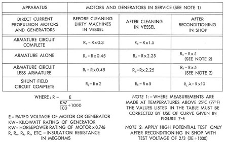
Figure 7-3. Minimum insulation resistance of dry direct current propulsion motors and generators based on readings of 25 degrees C or 77 degrees F.
101
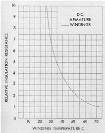
Figure 7-4. Effect of temperature on insulation resistance of insulated windings.
7A6. Explanation for use of table (Figure
7-3) for d.c. propulsion motors and generators.
a. General. The values Ra, Rc, Rf, and
Rj, indicate the minimum desirable insulation
resistances under operating conditions for the
circuits shown. When values less than these are
obtained, action to further investigate the cause
and remedy it, as indicated below, is necessary.
It is recommended that whenever insulation resistance
values less than Ra, Rf, Rj are obtained,
the equipment concerned should be cleaned at
the first available opportunity.
b. Armature circuit complete. Before any
cleaning is attempted, measure insulation resistance
of armature circuit complete, including
armature, compensating fields, commutating
fields, series fields, brush rigging, and
connections to machine terminals. This resistance is
measured by connecting the testing instrument
between one armature terminal and ground. If
the measured value is equal to or greater than
Ra, but cleaning appears desirable, an attempt
should be made to clean the machine in place
without disassembly except for the removal of
the access plates. If the measured value of
insulation resistance, after cleaning, is equal to or
greater than Rb, the machine should be placed
back in service; if the measured value of insulation
resistance is less than Rb, the several parts
of the armature circuit should be disconnected
and each part measured separately to determine
if any one part of the circuit is causing the
trouble. After the several parts are isolated from
each other, if one particular part is found to be
causing the trouble, that part should be treated
individually. When the several parts of the
armature circuit have been disconnected, and the
low insulation resistance still cannot be attributed
to any particular part of the circuit, the
machine should be recleaned to insure that it
has been properly done. If after a thorough
check of the cleaning, the insulation resistance
of the armature circuit complete is still less than
Rb and the trouble cannot be isolated, the machine
should be removed and reconditioned in a
yard or base shop at the first opportunity.
If the measured value of insulation resistance
for the armature circuit complete is less
than Ra before cleaning, the several parts of the
armature circuit should be disconnected from
each other and each part should be treated as
outlined below.
c. Armature alone. If the insulation resistance
of the armature alone is equal to or less
than Rc before cleaning, it should be cleaned in
the vessel. If the insulation resistance of the
armature alone when cleaned is equal to or
greater than Rd, the armature is suitable for
service.
If the insulation resistance of the armature
alone when it has been cleaned, is less than Rd,
the armature should be removed at the first
available opportunity to a yard, base, or tender
for reconditioning. After reconditioning, the
insulation resistance should not be less than Re.
After such reconditioning has been completed
the armature alone should be given a shop high-potential
test of 2/3 (2E + 1,000) volts, E being
the operating voltage of the machine.
d. Armature circuit less armature. If,
previous to cleaning, the insulation resistance of
the armature circuit less armature is equal to
or less than Rf, it should be cleaned in the vessel.
If the insulation resistance of the armature
102
circuit less armature when cleaned is equal to
or greater than Rg, that part of the equipment is
suitable for service. If, after cleaning, the
insulation resistance of the armature circuit less
armature is less than Rg, the various parts of
the circuit should be isolated to determine if
one part is causing the trouble. In some cases,
the low insulation resistance may be caused by
dirt, oil, or defective insulation at one spot such
as in one pole, or at one brush rigging stud, and
so forth. If the low insulation resistance cannot
be traced to some particular part or spot, all
parts of the armature circuit less armature
should be removed at the first opportunity for
reconditioning. After reconditioning, the insulation
resistance of the armature circuit less armature
should not be less than Rh. The reconditioning should
be followed by a shop high-potential
test of 2/3 (2E + 1,000) volts.
e. Shunt fields. If the insulation resistance
of the shunt field circuit complete prior to
cleaning is equal to or less than Ri, the shunt
fields and connections should be cleaned in
place. If the insulation resistance of the shunt
field circuit complete after cleaning is equal to
or greater than Rk, that part of the equipment is
suitable for service.
If the insulation resistance of the cleaned
shunt field circuit complete is less than Rk, each
shunt field coil should be disconnected and
measured separately to determine if one coil
is causing the trouble. If the cause of the low
insulation resistance can be traced to one pole,
that pole should be removed for reconditioning
or the coil should be replaced with a spare. If
the cause of the low insulation resistance cannot
be traced to one coil, all coils should be removed
for a yard, base, or tender reconditioning.
After reconditioning, the insulation resistance of
the shunt field circuit complete should not be
less than Rl.
f. Example of above discussion. Assume
that a submarine requires the cleaning or
overhaul of a propulsion generator. The rating of
the generator is 415 volts, 1100 kw.
The temperature of the generator is 25 degrees C,
or 77 degrees F, and the machine is dry.
R = 415 / ((1100/100) + 1000) = 0.410 megohms
Therefore the applicable minimum values
at 25 degree C are:
Ra
.41 X
.3
= 0.123 megohms
Rb
.41 X
1.5
= 0.615 megohms
Rc
.41 X
.45
= 0.185 megohms
Rd
.41 X
2.25
= 0.923 megohms
Re
.41 X
5.0
= 2.05 megohms
Rf
.41 X
.45
= 0.185 megohms
Rg
.41 X
2.25
= 0.923 megohms
Rh
.41 X
5.0
= 2.05 megohms
Ri
.41 X
2.0
= 0.82 megohms
Rk
.41 X
5.0
= 2.05 megohms
Rl
.41 X
10.0
= 4.1 megohms
1. Armature circuit complete. Assume
that the following conditions prevail:
a) Measured value of the insulation resistance
of the armature circuit complete is 0.160
megohms. This value is greater than Ra (0.123
megohms); and the armature circuit complete
should be cleaned in place.
b) After cleaning, the measured value of
the insulation resistance of the armature circuit
complete was 0.450 megohms which is less than
the minimum Rb (0.615 megohms).
c) The armature alone was disconnected
from the armature circuit complete and was
measured alone. A value of 1.2 megohms, which
is greater than Rd (0.923 megohms), was obtained,
indicating that the armature was satisfactory for service.
d) The measured value of insulation resistance
of the armature circuit less armature
was found to be 0.75 megohms which is less than
Rg (0.923 megohms), indicating that the armature
circuit less armature needed additional
cleaning or that there was some isolated low-resistance
path. The compensating windings, the
commutating windings, and the brush rigging
were disconnected from each other and measured
separately. The compensating winding
measured 4.0 megohms, the commutating winding
measured 1.0 megohms, and the brush rigging
measured 4.0 megohms, indicating that a
low-resistance path to ground was somewhere
in the commutating pole winding. Each commutating
pole winding was disconnected and
measured separately and it was found that one
commutating field pole had lower insulation
103
resistance than any of the other commutating
field poles. Upon further investigation, it was
found that one of the less accessible spots of the
pole had not been adequately cleaned. After
cleaning, the insulation resistance of the pole in
question was measured and found to be equal
to all of the other poles. All parts of the
armature circuit less armature were then reconnected
and the insulation resistance measured. A value
of 1.2 megohms which is greater than Rg (0.923
megohms), was obtained, indicating that these
parts were satisfactory for service. The armature
was then connected in the circuit and the
armature circuit complete gave a measured
insulation resistance value of 0.750 megohms
which is greater than Rb (0.615 megohms), and
the armature circuit complete was ready for
service.
2. Shunt field circuit. The measured value
of insulation resistance of the shunt field circuit
complete before cleaning was 0.10 megohms
which is less than the minimum value of Ri (0.82
megohms). Each shunt field coil was disconnected
and tested separately; one coil was found to
have much lower insulation resistance than any
of the other coils. The defective coil was removed
and it was found that the insulation between
the coil and the metal pole piece had been
damaged, allowing a low-resistance path to
ground. The damaged insulation was renewed
and all the shunt field coils were cleaned and
reconnected. The insulation resistance then
measured 3.50 megohms, which indicated that
the shunt field circuit complete was ready for
service.
7A7. Repairing defective insulation. Windings should
be cleaned and dried before any repairs are attempted.
When a defect is located,
either a permanent or a temporary repair should
be made as circumstances will permit. All connections
should be maintained tightly and suitably taped where
necessary. Wedges should be
maintained tightly in their slots and any loose
space should be filled with slot fillers. Binding
bands and bolted and soldered connections
should be checked because the effect of magnetic stresses,
vibration, and cycles of temperature variation constantly
tend to loosen bands
and connections. Field coils should be checked
for tightness on field poles and for evidences of
bruises due to retainers. Insulation will occasionally
require a coating of insulation varnish.
Only high-grade air-drying insulating varnish
must be used. Apply two thin coats only, suitably
thinned in accordance with the directions
of the varnish manufacturer. Care should be
taken to avoid clogging air vents, and any excess
varnish should be removed before it sets.
All insulating surfaces such as mica, cone
extensions, brush insulation, and so forth, should also
be coated with varnish. It is essential that varnish
be applied only on clean, dry surfaces after
all necessary repairs and cleaning have been
effected. Varnish may be applied either by
spraying or with a brush. It should be noted
that the application of varnish will not permanently
increase the insulation resistance or dielectric
strength of the insulating material and
accordingly cannot be used as a substitute for
repairing or replacing defective insulation.
7A8. Condensation. To prevent condensation during
extended shutdown periods, the temperature within
the machine must be kept higher
than the outside temperature. Condensation can
be prevented, or eliminated, if found, by circulating
heat through the machine. A convenient
means of heating the machines is to leave the
shunt fields energized at a low current. Do not
exceed the maximum field current allowed in
the manufacturer's instruction book for nonrotating machines.
CAUTION. Always secure the circulating
water to the main motor or generator coolers
when the machines are secured. If this precaution
is not observed, condensation may take
place on the cooler core.
Moisture absorbed by insulation or condensed on its
surfaces may result in short circuits or grounds.
The dielectric strength of the
insulation is lowered temporarily while moisture
is present and may be permanently lowered if
deterioration occurs. For these reasons, moisture
should not be allowed to accumulate, and
a machine should not be placed in service
without first making certain that the insulation is
dry.
Insulation may be dried out with a hot air
heater, allowing the hot air to enter through a
port at the bottom of the machine and the
104
moisture-laden air to escape through a port at
the top. If insulation resistance is not too low,
reduced current may be passed through the
shunt field coils. The voltage and current should
be gradually raised as the machine dries. Constant
circulation of air is important. If an outside
source of air is used, make certain that the
air is clean and free of moisture. It is a good
practice to energize with a low current daily all
fields on machines that are not in use in order
to dry them and keep them above room temperature.
The insulation resistance should be measured before,
and at intervals during, the drying
process. The interval between readings may vary
with the rate of drying and the convenience in
making the measurements. The insulating resistance
decreases rapidly at the early stages of
drying; but as the temperature becomes constant
and evaporation progresses, the insulation
resistance begins to increase, rapidly at first,
then at a slower rate. When the readings reach
a constant value and are sufficiently high, the
drying-out process is complete and may be discontinued.
Complete drying may take 24 hours
or longer, depending on the heat and air circulation.
7A9. Brushes and rigging. a. General. The
brush rigging is doweled in its proper position
by the manufacturer. A machine must never be
operated unless these dowels are tight and the
rigging properly positioned. In the event of a
change of position, old marks must be obliterated
and new reference positions definitely determined and marked.
Brush brackets should be kept in their original
positions so that they are square with the
commutator segments and so that the distances
between the brushes around the commutator are
equal.
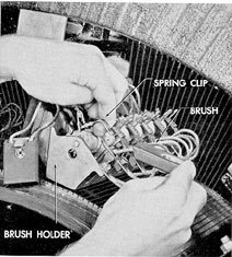
Brush holders are removable and fit in
grooves to assure proper alignment. Brushes
should not be loose in the holders, nor should
they be so tight that they do not move freely.
There should be a clearance of 0.005 in. to 0.025
in., measured in line with the shaft, between
the brush and the holder. The clearance in the
other direction, perpendicular to the commutator
bar, between the brush and the holder should
be 0.005 in. to 0.014 in. Check the brushes
frequently to see that they are not sticking in the
holders, that leads are firmly attached to the
brushes and the holders, and that the pigtails
are not rubbing on any part of the machine.
Worn-out brushes must be replaced before they
reach the end of their travel and break contact
with the commutator.
Figure 7-5. Brush removal.
If sparking of the brushes is encountered,
check for the following possible causes:
1. overload
2. incorrect positioning of the brush rigging
3. worn-out, burned, or incorrectly fitted
brushes
4. brush holder brackets out of alignment
5. rough, dirty, or insufficiently undercut
commutator
6. open circuit or loose connection in the
armature
7. loose connection between pigtail and
brush or pigtail and holder
105
NOTE. Brushes having loose pigtail connections,
while they may not spark themselves,
will often cause other brushes to spark because
the defective brushes do not take their share of
the load.
b. Procedure for reassembling brush holders.
Whenever it becomes necessary to disturb
the original adjustment of the brush holders,
the following procedure should be followed in
reassembly:
1. Set up the brackets with the brush holders
in place and wrap a long strip of paper
around the whole circumference of the commutator.
Mark the lapping points of this paper;
lay it on a flat surface, and divide the space
between the marks into as many equal spaces
as there are brush arms. Mark each division
point, wrap the paper around the commutator,
and adjust the brush brackets until the toes of
the brushes of the different brackets just touch
the marks. All brush holders should be the same
distance from the commutator - not less than
0.080 in. or over 0.100 in. The toes of all brushes
on one bracket must be in line with the edge of
one commutator segment. If a bracket is out of
line, loosen the bolts and adjust to the proper
alignment by shimming or filing under the
bracket head. Occasionally slight filing to
increase the clearance in the bolt hole may be
necessary. Correct staggering of the brushes has
been provided for by suitable drilling of the
brush holder brackets.
2. After the brushes have been properly
spaced, they must be sanded to fit the curvature
of the commutator. Fine sandpaper may be used.
Do not use emery or carborundum. Remove the
carbon dust with a cloth as it will cause serious
trouble if allowed to collect on the winding. To
fit the brushes with sandpaper, lift two or three
of the brushes sufficiently to permit a sheet of
sandpaper to be inserted between the brushes
and the commutator face with the abrasive side
of the paper toward the brushes. Move the sandpaper
along the commutator face in the direction from the
heel of the brush to the toe; release the brush
pressure as the paper is drawn
back. It is important to keep the paper down
on the commutator face to avoid rounding the
edges of the brushes. The brushes in one side of
the holders should be sanded separately from
those on the other side, moving the sandpaper
always toward the center of the holder with the
drag on the brush also toward the center. Continue
the sanding operation until the brushes
make firm, even, and complete contact with the
commutator face.
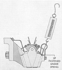
c. Spring tension. Frequent adjustment
of the spring tension is not necessary, but it is
advisable to check the springs and possibly the
tension when the brushes are worn down approximately
halfway. The brush pressure should
be about 2.5 psi of contact area between the
brush and commutator. A small spring balance
may be used for checking the brush spring pressure
as shown in Figure 7-6.
Figure 7-6. Method of measuring brush spring pressure.
d. Brush yoke setting. Shifting of the
brushes around the commutator effects both the
compounding and commutation. In a generator,
the armature current reduces or increases the
main field magnetization, depending upon
whether the brushes are ahead of, that is, shifted
in the direction of rotation of, or behind the
true neutral point, thus having considerable influence
on the compounding. To prevent sparking, the brushes
must be held in such a position
that the armature coils short circuited by the
brushes are under the influence of the
106
commutating poles. Occasional shifting from an exact
center to produce slight changes in compounding
is permissible. Even the most careful setting
with a tram is subject to slight errors, and, for
a final adjustment, slight changes in brush position
may be necessary.
If a brush rigging has been completely disassembled,
it will, of course, be necessary after
assembly to locate the proper setting of the
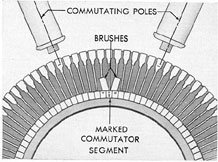
yoke. On all machines, the mechanical neutral
is determined by the factory marks on the armature
slots and commutator bars. Rotate the
armature until two slots, which are marked, are
equidistant from the center lines of two cominutating
poles. Set the brushes of the stud between
the two commutating poles at the center of the
group of commutator bars which are marked
on the ends. This will be over the center of the
bar which is stamped with an identifying mark.
The setting obtained in this way is approximate only,
and must be checked by observation
of the machine under load.
Figure 7-7. Factory mark on armature slots and commutator bars.
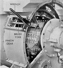
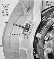
e. Rotating the brush rigging. Geared
brush yokes used on General Electric machines
are rotated by means of a pinion gear and
wrench which are supplied as special tools.
First, the upper cover on the side of the machine
on which the yoke clamping arm is located must be
removed. Next, the clamping arm
is removed, the clamping bolt at the top of the
yoke loosened, and the two flexible connections
disconnected. The pinion is engaged with the
gear teeth on the yoke and the pinion bracket
secured to the frame. The rigging can now be
rotated with a wrench.
On the other type machines, the rigging is
rotated by removing the dowel which secures
the yoke and inserting a steel bar in the holes
provided on the rim of the yoke.
Figure 7-8. Wrench and pinion gear installed for rotating G.E. main motor brush rigging.
Figure 7-9. Wrench and pinion gear installed for rotating G.E. main generator brush rigging.
107
7A10. Care of commutators. a. General.
Successful operation and long life of a machine
depend largely on keeping the commutator surface
clean and free from oil and dirt. This does
not mean that a commutator should be kept
bright and shiny. The proper color of the
commutator after the machine has been run for
some time should be uniformly medium or dark
chocolate.
The commutator should be wiped occasionally with
a piece of dry canvas. Waste or soft
linty material must never be used. Oil, vaseline,
or any of the so-called commutator compounds
must not be used.
Sandpaper should be used lightly on the
commutator, if at all, and emery cloth must
never be used. Emery is a metallic conductor
and, if lodged between segments, causes short
circuits. If it does become necessary to use
sandpaper to smooth a commutator, the paper
should be fitted in a wooden block, shaped to
the curvature of the commutator.
If the mica between the segments becomes
higher than the copper, a hacksaw blade with
the set ground off may be used for undercutting
the mica. Good judgment should govern the
frequency of this treatment; undercutting the
mica too frequently makes the slots too deep
and permits a dangerous amount of carbon dust
to collect in the undercut. After cutting down
the mica, it is desirable to bevel the corners on
the bars very lightly and to sand the commutator
lightly to remove any rough spots from the
edges of the segments.
A freshly turned commutator, or one on
which the surface has been renewed, should be
run under light load for approximately 24 hours.
The commutator surface should then have a
uniform polish. During the initial period of
running, the commutator surface should be
wiped with dry canvas at frequent intervals in
order to remove any carbon deposit. Do not use
waste or other linty material. No lubricants of
any kind should ever be applied to a commutator.
The brushes are self-lubricating and may
leave a soft black deposit on the commutator
when first placed in service. This deposit should
be wiped off. The dry canvas or other nonlinty
material used for wiping may be wound around
a block and held against the commutator.
When in service, the commutator should
maintain a dull polished surface. Blackening of
all the bars indicates poor adjustment of the
commutating field or incorrect brush pressure.
Blackening of groups of bars at regular intervals
may be due to the same cause or to poor
brush contact. Blackening at irregular intervals
indicates a rough or eccentric commutator that
can be corrected satisfactorily only by stoning
or cutting. This is a major repair and is usually
performed by a tender or at a naval shipyard.
b. Brush vibration and sparking. Noisy
brushes are generally the result of a rough
commutator or too much clearance between the
commutator and brush holders. Under some
conditions, brush vibration accompanied by noise may
appear at light loads. This is characteristic of
some brushes and will disappear as soon as the
brushes carry appreciable current. Brush vibration
frequently causes sparking. Sparking of any
kind should be watched closely to determine
whether or not the bars are being damaged.
Due to slight mechanical unbalance, commutators
may possibly run with an eccentricity
of several thousandths of an inch at some
speeds. This is not necessarily cause for
concern, unless other damaging effects are noted.
No attempt should ever be made to tighten or
loosen the commutator clamping bolts for any
reason.
c. Machine vibration. The source of any
appreciable vibration of a machine should be
located and corrected. A small amount of vibration
may be expected from the diesel engine,
but since all rotating parts of the generator are
carefully balanced before installation, any
existing vibration is usually the result of shaft
misalignment. Newly fitted oil seals which rub
on the shaft may also cause vibration.
7A11. Air gaps. Shims are provided between
the poles and the frame for adjustment of the
air gaps. The normal air gap for the main and
commutating poles varies in generators of different
manufacture. Refer to the manufacturer's
instruction book for specific dimensions. When
assembling any pole, the air gaps of the other
108
poles on the same machine should be measured
at the same time and the loose pole set to agree.
In measuring the air gap, it is important
that the poles be concentric about the armature.
In case all poles are removed at once and reassembled,
the air gap should be set to the factory specifications
if a tapered gage is used, and
to shipyard readings if feeler gages were used
originally, and are being used again. The air
gap of a pole should be recorded, preferably
before removal, with gages that are to be used
for reassembly and the gap then reset to the
original setting. Air gaps must be measured
over a tooth on the armature which has been
scraped clean of varnish. The location of this
tooth is indicated by a mark on the armature
next to the core on each end. Measurements are
made by rotating this tooth under each pole,
measuring from the same tooth to the pole in
each case. The frame head supporting the bearings
and the bearing housing are doweled after
the air gaps have been adjusted at the factory.
In adjusting the air gap, it is not necessary to
allow for movement of the shaft in the bearings
due to rotation. The air gaps are sufficiently
large so that normal bearing wear will not have
any influence on the operation. It is more important
that all the air gaps be uniform than
that their average be equal to the designated
nominal value.
The commutating poles are provided with
both magnetic and nonmagnetic shims. Whenever
they are removed, the same thickness of
nonmagnetic shims should be replaced as were
removed.
7A12. Bearings and lubrications. a. Main
motor bearing lubrication. The bearings of
geared motors are fed from the reduction gear
lubrication system. The pressure supplied by
the main pump is adequate for lubrication down
to the dead slow speed (38 propeller rpm).
When operating at dead slow speed the oil pressure
is extremely low. However, if a continuous
flow of oil can be observed in the oil sight flow
indicators, the bearings are adequately lubricated.
The standby lubricating oil pump is used
to replace the main pump when the oil pressure
drops below 5 pounds, at which time an alarm
warns the electrician on watch that the pressure
is low. The standby pump is also used to pre-lubricate
the bearings after a shutdown. The
bearings of direct drive motors are lubricated
from separate motor-driven pumps. The pump
controllers have a selector switch by which the
pumps may be run at slow speed in order to
obtain the quietest operation. This condition
should never be used at shaft speeds in excess
of 80 rpm. The oil flow at full speed should be
approximately 1 1/4 gallons per minute for the
journal bearings and 2 1/2 gallons per minute for
the thrust bearing.
b. Main generator bearing lubrication.
The main generator bearings are the same type
as those used on the main motors but they are
lubricated from their respective main engine
lubricating systems. The bearings are designed
to operate with a 10 to 15 psi oil pressure at the
bearing. Flow through the bearing should not be
less than a quart per minute at normal speed.
Any pressure that results in the required flow is
satisfactory. Possible plugging is avoided by
the size of the oil feed lines and the openings in
the bearings which are not less than 3/16 in. in
diameter. The flow of oil in passages of this
size is not limited sufficiently at practical feed
pressures. A bypass is, therefore, installed in
the piping to divert a part of the flow around
the bearings in order to prevent overlubrication
and the possibility of excess oil entering the
generator.
c. Temperatures of oil and bearings. The
temperature of oil supplied to the bearings
should not exceed 130 degrees F. The maximum safe
operating temperature of the bearings is 180 degrees F.
d. Causes of overheated bearings. Overheated bearings
may result from a number of
different causes, among which the following are
most frequently found:
1.
insufficient oil
2.
inferior grade of oil
3.
dirt and grit in oil
4.
clogged oil lines
5.
poorly fitted bearings
6.
bearings too tightly set up
7.
scratched or corroded journals
8.
conduction from overheated electrical parts
9.
misalignment of shafting
109
Dirt may cause the oil sight glass to indicate oil
when none is present. A clogged top
vent will have the same effect. Lack of end
play will cause binding or heating, the trouble
becoming aggravated as the shaft expands. A
bent shaft will cause vibration and grinding at
the journals. All of these troubles should be
guarded against by frequent, intelligent inspections.
Until a machine is available for overhaul,
overheating may often be checked by the use of
a liberal supply of fresh, cool oil, or in an
emergency, by the use of water. The electrical
parts should be kept clear of either oil or water.
c. Removal of bearings. The commutator
end bearing housing on generators and motors
is enclosed by a cover plate which must be
removed to gain clearance for lifting the bearing
housing over the bearing. Lifting jacks are provided
for lifting the rotor slightly. This permits
rotating the lower half of the bearing to the top
of the shaft for removal. During removal, care
must be taken to prevent damage to the external
surface of the bearing which fits the housing. The
lifting jack must be slacked off after
the bearing is replaced. Serious damage will
result from neglect of this precaution.
7A13. Cooler maintenance. a. Cleaning.
Periodic cleaning of water tubes is necessary to
remove any foreign matter carried in by the
cooling water. Access to the tubes on all types
of coolers is obtained by removing the water
boxes or headers. The interior of the tubes may
be cleaned with nonabrasive brushes, rubber
plugs, compressed air, or by any standard approved
method used for cleaning condenser
tubes.
Strainers in the water inlet line and the inside of
the core tubes should be cleaned as
frequently as necessary to provide an unrestricted
flow of water.
b. Prevention of moisture condensation.
Condensation of moisture in the air cooling system
must be prevented in order to avoid the
possibility of water being carried into the
generator or motor and deposited on the windings.
Since it is difficult to determine accurately the
temperature at which condensation will occur,
the best practice is to adjust the cooling water
flow until it is just sufficient to maintain the
temperature of the air out of the machine at
about 10 degree F below the maximum allowed in the
manufacturer's instruction book.
CAUTION. Whenever the load is changed,
the temperature should be checked immediately
and the cooling water adjusted accordingly.
Failure to do this will cause great changes in
the injection temperature of the cooling water.
c. Control of cooling water. The flow of
cooling water is controlled by valves and, in the
case of the motors, also by speed control of the
pump. The piping is arranged so that any cooler
section may be cutout and the machine operated
on the remaining section or sections. When operating
on reduced coolers, the machine temperatures
must be watched closely and the load
reduced if necessary.
d. Zinc plates. Each cooler section contains protective
zinc plates which protect the
cooler tubes from the electrolytic action caused
by salt water. These plates must be inspected
at regular intervals and replaced when approximately
75 percent of the plate has been dissolved. Neglect
of this inspection and renewal
leads to serious cooler deterioration and possible
damage to the motor or generator through
the leakage of the cooling water into the machine.
B. CABLES
7B1. Insulation resistance measurements of
cables. a. General. The primary purpose in
making insulation resistance measurements of
cable installations is to determine the condition
of the cable in order that deterioration, which
would result in eventual failure, may be discovered
and remedied. Insulation resistance and
methods of measuring its values are explained
in Sections 7A2 and 7A3.
b. Factors affecting resistance values. The
following factors must be considered in measuring
insulation resistance of cables:
1. Other apparatus connected. Any equipment
connected in the circuit when a measurement is
made will result in a reading that will
include the connected equipment. For example,
when measuring the insulation resistance of the
positive cable connecting a generator to a
110
switchboard, the cable should be disconnected
at each end. If this is not done, the measurement
will include the insulation resistance of the bus
work, all apparatus connected to the bus, the
generator, and the negative cable. Since the insulation
resistance of this other apparatus is in
parallel with that of the cable, the measured
value of the combination may be considerably
below the value that would be obtained if the
cable were disconnected and measured separately.
For convenience, initial measurements may
be made with the cable only partially isolated
by opening switches, circuit breakers, or other
disconnecting devices in the circuit. If the value
then obtained is satisfactory as compared to
previously recorded values that were obtained
under the same conditions, or to limiting values,
no further isolation of the cable will be necessary. Otherwise, it will be necessary to completely disconnect the cable and measure it
alone before a conclusion can be drawn as to
its condition.
2. Total quantity (number and length) of
cable. When insulation resistance of cables is
to be measured, its length must be taken into
account. The total insulation resistance of a
particular length of cable is the resultant of a
number of small parallel individual leakage
paths distributed along the cable sheath. In
order to have a common unit of comparison, the
cable insulation should be expressed in ohms or
megohms per foot of length. This is determined
by multiplying the measured insulation resistance
of the cable by its total length. It should
be noted that in so far as insulation resistance
measurements are concerned, it makes no difference
whether the cables are in series or in parallel, and
consequently the total length should include the sum
of all the lengths of cable connected at the time of
measurement. For example, if 2 cables, each 100 ft
long, are connected
together, even at only one end, at the time of
measurement, the total length is 200 ft and the
insulation resistance per foot is 200 times the
measured value. The foregoing should not, however,
be confused with the total length of individual
conductors when considering multiple
conductor cable. For convenient comparison
purposes, the data applicable to multiple
conductor
cable are based on the insulation resistance between
all the conductors connected together and the sheath
or ground. Thus, when
reference is made to total length of multiple
conductor cable, it means the length represented
by the sheath and not by the sum of the length
of individual conductors within that sheath. For
example, the total length of 300 ft of MHFA-7
(7-conductor cable) is 300 ft, not 7 times 300 ft.
Consequently, the insulation resistance per foot
with all conductors connected together, is 300
times, not 2100 times, the measured value.
3. Type of cable. Insulation resistance
varies considerably with the nature of the
insulating material employed and the construction
of the cable. It is possible, therefore, to judge
the condition of a cable as determined by its
measured insulation resistance only when it is
considered in relation to the typical characteristics
of the particular type of cable in question.
The heat and flame resistant cables (type HF
series) are now in general use. The curves shown
in Figure 7-10 are applicable only to the type
specified.
4. Temperature. Fairly accurate temperature
measurements on the sheath of the cable
must be made in order to permit a reliable
interpretation of the insulation resistance measurements.
The temperature should be measured by
means of thermometers, attached to the cable
sheath, or armor, at several points along the
length of the cable. An average is then made of
these values. The thermometer bulb should be
placed in direct contact with the sheath, or
armor. Scrape away the paint at the point of
contact. Hold the thermometer in place with
pads of felt or other, heat insulating material
placed over the bulb and secured with tape. The
number of thermometers used and their location
should be such that they indicate a representative
average of the sheath temperature of the
entire cable being measured.
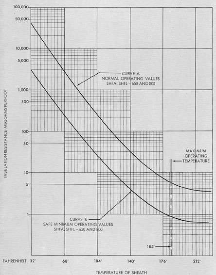
The effect of temperature on insulation resistance
of SHFA and SHFL type cables is
graphically illustrated by the curves shown in
Figure 7-10 which show the resistance changes
which may occur in the normal operating temperature
range as measured at the cable sheath.
111
Figure 7-10. Insulation resistance vs. sheath temperature, SHFA, SHFL, sizes 650 and 800.
112
Curve A of Figure 7-10 is the characteristic
curve of insulation resistance and temperature
for normal types SHFA and SHFL, size 650
and 800 cables. In referring to the curve, it
should be noted that the insulation resistance
falls rapidly with increase in temperature. Curve
B of Figure 7-10 indicates a safe minimum insulation
resistance for the cables, when used at
submarine propulsion voltages.
c. Procedure. The procedure in measuring insulation
resistance should be as follows:
1. Disconnect the cable from other equipment,
in so far as practicable, and make a record of the
connections remaining.
2. Measure the average sheath temperature.
3. Ground the cable for a few seconds to
remove any static charge.
4. Measure the insulation resistance by
means of a suitable instrument.
For single conductor cable (SHFL, SHFA,
SDGA) there is but one insulation resistance to
measure; that between the conductor and armor
of lead sheath. For multiple conductor cables
(MHFA, THFA, etc.) the insulation resistance
should be measured from all conductors connected
together to the armor, or to the metallic
structure, or ground, to which the cable is attached
if the cable is without armor. Measurements should
also be made from each conductor
to every other conductor. For example, in a 3
conductor cable this results in 4 measurements
from armor or ground to conductors 1, 2, and 3
connected together; from conductor 2 to conductor 3.
The lowest of these values should be
used as the measured value.
5. Determine the total length of the cable
in the circuit.
6. Multiply the total length by the measured
resistance, thus obtaining the resistance in
megohms per foot.
7. Compare the measured megohms per
foot with the minimum safe megohms per foot
indicated by the applicable curve at the measured
average sheath temperature.
8. If previous measurements were made of
exactly the same installation with the same
equipment in the circuit and at the same
temperature, compare the present resistance values
with the previous values and note what change
has occurred.
C. AUXILIARY MOTORS AND MOTOR GENERATOR SETS
7C1. General maintenance of auxiliary motors
and motor generator sets. a. Cleaning.
The interior and exterior of the machines must
be kept clean at all times. Inspect the machines
daily for presence of dirt, oil, and moisture, and
wipe the machines thoroughly if such foreign
matter is found.
b. Insulation resistance. Moisture on the
commutator, armature, or field coils causes
leakage paths that lower the insulation resistance
and result in a ground. Periodic checks of the
insulation resistance should be made and recorded,
following the same general procedure as
outlined for main motors in Section 7A3. Since
no specific acceptable values can be established
such periodic tests are useful in detecting weaknesses
of insulation or accumulations of moisture
or dirt. Then by comparing readings with
those previously recorded under approximately
similar conditions of temperature and humidity,
it can be determined when cleaning, drying, or
other servicing of the machine is necessary.
If a test indicates that the insulation resistance
is below an acceptable value, all parts
should be wiped with clean cloths. Do not use a
cloth that will deposit lint in the windings. If
the insulation resistance remains low, the windings
should be cleaned with an approved solvent
solution. The commutator heads and cross connectors
should also be thoroughly cleaned.
Dry the windings as outlined in the section
that follows (7C1c) until the insulation resistance
becomes constant; then coat windings and
adjacent parts with a high-grade air-drying
varnish. Never apply varnish over damp or dirty
parts, and do not depend on insulating varnish
alone to increase the insulation resistance. All
parts must be cleaned and defects repaired before
varnish is applied.
113
c. Drying windings. Windings may be
dried by circulating hot air through the machine
by means of a fan. A spare heater or a bank of
lights may be used as the source of heat. Care
should be taken to see that the heat is distributed
evenly so that all parts will have the same
temperature and dry evenly.
Drying can also be accomplished by passing
reduced current through the shunt field coils.
It should be noted, however, that short circuits
may develop in the coils if this method is used
while the coils are wet or actually grounded.
When drying a coil with power applied,
check the temperature of the coils every
15 minutes for a few hours. If the temperature increases
to a point where the coil is too hot to touch, shut
off the current.
NOTE. Do not continue drying after the
insulation resistance becomes constant.
If insulation resistance is still low, determine which
parts of the machine are defective and make any
necessary repairs.
d. Armature. It is important that air
spaces between coils be open for free circulation
of air. This is also true of the openings between
the shaft and core plates. Do not allow dirt or
other foreign material to accumulate on the
armature, particularly in locations where it will
restrict the free circulation of air. It is of major
importance that no oil or dirt accumulate above
the commutators. Large creepage distances are
provided between the commutator bars and
heads. Keep this portion dry and occasionally
coat with special insulating compound supplied
for this purpose. Armature coils should be
cleaned regularly and should occasionally be
thoroughly dried and varnished in accordance
with general instructions. A vacuum cleaner
with a small inlet is effective in cleaning
between the coils, and is much more desirable
than compressed air. Steel banding wire should
be checked regularly and replaced if any bands
show signs of defect.
e. Commutators. Successful operation and
the longevity of machines depend largely on the
degree to which the commutators are kept clean
and free from oil or dirt. Wipe the heads and
ends of V-rings frequently to keep them in good
condition. Use special insulating compounds for
these parts. Keep the undercut between copper
segments clean. This will prevent burning between
bars and possible short circuiting of armature coils.
Do not sandpaper or stone commutators unless their
condition makes it necessary. Never
use emery cloth or paper on a commutator. If
sanding or stoning should be necessary, make
sure that the paper or stone fits the surface of
the commutator.
After the machines have run for a short
period, commutators usually acquire a dull
brown finish. This is the proper surface. Do not
try to keep the commutators bright and shiny.
If the mica between commutator segments becomes
higher than the copper, the slots should
be undercut. This is easily done with a hacksaw
blade which has the set ground off. Excessive
undercutting with a sharp instrument must
be avoided because it will wear down the mica
to such a point that an excess amount of carbon
dust may collect in the undercut. After the mica
has been cut down with a saw blade, file, or
other instrument, it is desirable to sand the
commutator lightly to remove any burrs on the
edges of the copper segments.
If commutators have high bars or are
rough, they should be ground smooth,
otherwise the condition may cause excessive sparking
and heating of the commutators or severe burning
of the bars and possible loosening of the
armature leads.
Grinding should be done at as high a speed
as practical, and with extreme care. Make several
light passes over the commutator. When
finished, undercut the mica and sand the
commutator lightly. Canvas should be fitted around
the armature so that copper dust will not enter
the spaces between the windings. If practical, a
vacuum cleaner should be placed in a position
to collect the flying dust. When finished, the
machine should be thoroughly cleaned. Compressed
air should not be used for this purpose
as it will blow the copper dust through the
entire machine. Commutator clamping nuts
should not be disturbed.
f. Main poles and coils. Main poles are
114
held to the motor frames by bolts that may be
removed with standard wrenches. The coils and
adjacent parts should always be kept clean. Dirt
must not be allowed to collect between the coils
and magnet frames. If dirt cannot be readily
removed, release the holding bolts and wipe the
coils and frames with a cloth. Dry the coils,
coat with air drying insulating varnish, and
tighten the bolts. Make certain that the bolts
are thoroughly tightened, and that there is no
misalignment of the poles.
If a coil should become damaged, remove
it, together with the pole piece, from the
machine. This can be done without removing the
armature. When removing the coil from the
pole, or when reassembling, do not damage the
sheets of insulation wrapped around the pole.
Should it be necessary to replace any of the
taping, dry the coil thoroughly and coat it with
air drying insulating varnish before retaping.
Never apply varnish to a damp coil, for it will
tend to seal in the moisture and may cause
trouble. When removing a coil, be sure to check
the air gap before releasing the holding bolts.
Then disconnect the cross-connectors and
check the markings to make certain that the
connectors will be replaced in their proper
positions. When the bolts have been released,
observe the number and thickness of the shims.
Withdrawing or replacing a coil should be done
very carefully so that the pole will not damage
the armature. The use of a sheet of pressboard
rubbed with paraffin and inserted in the air gap
often makes this operation easier.
g. Commutating poles and coils. Commutating poles
are held in the same manner as
the main poles. The method of removing and
replacing a commutating coil is similar to that
for a main field coil.
The voltage drop across any one commutating coil
will be very low, so there is little or
no chance of short circuited turns. However, the
voltage to ground may be practically as high
as the line voltage. Also, the commutating coils
are of taped copper bar. Therefore, it is important
that no dirt collect on the insulating plates
or lodge between the plates and magnet frames.
If it is impossible to remove readily the dirt
between the plates and the frame, the poles may
be released in the same manner as the main
poles. Coils are dipped in insulating compound
and baked and are therefore, a solid piece.
Disassembly of a coil from a pole may be easier if
the coil is heated after it has been removed from
the frame. Coils are fitted on the poles from
the frame side so that it is unnecessary to remove
the pole shoes. The method of removing a
commutating coil is similar to that of removing
a main field coil. When tightening cross-connectors
to terminals of a commutating coil, use a
feeler gage to insure full contact. Commutating
poles are provided with both magnetic and nonmagnetic
shims. The same thicknesses of both
types should be replaced as were removed.
h. Brushes and rigging. The brush rigging is of
rigid construction in order to eliminate
vibration. All studs must be kept tight. Insulator
plates must be cleaned regularly. The machines should
never be run until the brush rigging is locked in its
proper position.
Brush holders should be kept in their original
position so that they are square with the
commutator segments and so that the distances
between the brushes around the commutator
are equal. Brush holders are removable and fit
in grooves to assure proper alignment.
The brushes furnished for each application
are of a type and grade selected to give best
operation. The type and grade should not be
changed without consulting the manufacturer
of the equipment. Brushes should not be loose
in the holders, neither should they be so tight
that they do not move freely. New brushes
should be sanded to fit the surface of the commutator.
Care must be taken during this operation to make
sure that carbon dust is not blown
through the machine. Spring tension on the
brushes should be approximately 2 psi of brush
surface. If brushes spark, due to a rough commutator,
little or nothing is accomplished by
setting the springs for higher tension.
Continuous operation under these conditions will cause
excessive heating of the commutator which may
result in loosening of the armature leads.
Correct the trouble at its source.
115
D. AUXILIARY CONTROL EQUIPMENT
7D1. Magnetic contactor starting panels.
a. Cleaning and inspection. Control equipment
should be cleaned and inspected regularly
to prevent breakdowns or serious shutdowns.
Dust that collects on the working parts of a
controller must be removed. Excessive wear of
moving parts can be avoided if parts are kept
free of foreign matter.
b. Lubrication. The armature lever shaft
of contactors should be lubricated occasionally.
A light engine or machine oil should be used.
The quantity of oil used should be kept to an
absolute minimum so that the oiled parts do
not become dust collectors. Oil must not be allowed
to collect on the sealing surfaces of operating
magnets since improper operation of the
device will result.
c. Contacts. Contacts should be renewed
before their wear allowance is completely gone.
When copper contacts become badly roughened
or burned, they should be smoothed off with a
fine file, taking care to remove only as little
copper as is necessary to reestablish good contact.
Silver contacts should not be filed except
in extreme cases of roughness. A silver contact,
although badly oxidized, can still make good
contact.
The main and auxiliary contactor contact
surfaces must be kept clean and uniformly bearing.
The contact springs should be kept at an
even tension or replaced if found defective.
Protective overload and no-voltage devices should
be inspected and tested periodically. On these
tests, the proper operation and sequence of the
contactors should be noted. The need for minor
repair or adjustment to one contactor will often
disable a panel. The flexible connector terminals
should be kept tight and other possible sources
of open circuits watched.
d. Arc chutes. On contactors equipped
with blowouts, the arc shields should be replaced
before the material is burned away
enough to allow the arc to touch the blowout
pole piece.
e. Insulation. The insulation on wires
and coils may sometimes be damaged due to
vibration and friction against other parts. Parts
with damaged insulation should be reinsulated
as soon as the damage is discovered, and wherever
possible, the cause of the damage should
be removed,
E. PANELS AND SWITCHBOARDS
7E1. General maintenance of panels and
switchboards. Panels and switchboards should
be wiped frequently with a soft brush having no
metallic binding. If it is necessary to clean off
anything other than dust, a soft flannel cloth
or a piece of chamois should be used. Cotton
waste or cloths that leave lint must not be used.
Frequent examination must be made to insure that all
connections are tight.
The condition of the wires behind the board
should be checked periodically.
The tendency of the ship's structure to
weave sometimes causes enough movement of
the wires behind the board to result in their
abrasion and consequent breakdown.
Surface moisture must be kept at a minimum
on all panels to hold up the circuit insulation
resistance readings. Its presence on a panel
will often account for low circuit insulation
resistance readings. If it becomes necessary
to remove moisture, use a flannel cloth.
Alcohol must never be used for cleaning
panels. This substance is not only inflammable,
but its use will break down the finish surfaces
of panels and of the instruments mounted on
them.
The use of an approved lacquer is recommended
since it not only improves appearance,
but also produces a polished surface which does
not absorb and hold moisture.
116
F. HEATING UNITS
7F1. General maintenance. Before any attempt
is made to work on a heater or switch, all
power lines to the unit must be disconnected.
Immersion type heating units used in lubricating
oil heaters should be removed and inspected
periodically for the presence of carbon
on the heater blades. This deposit is caused by
continuous contact with oil. If an accumulation
of carbon is found, the blades must be scraped
clean, then reinstalled.
Contacts in the terminal box and switch
should be checked and tightened if necessary.
Care must be taken to see that immersion
type units are not turned on unless they are
immersed. The elements burn out quickly when
current is applied to a dry unit.