3A1. General. Fundamentally, the construction
of the main propulsion control equipment
or control cubicle produced by General Electric,
Westinghouse, and Cutler-Hammer is similar.
Individual components may vary somewhat in
design; their locations and methods of installation
in the assembly may differ; cables and conduits
will be found routed differently; but each
assembly as a whole performs the same function
and is operated in a similar manner.
This chapter, with the exception of Sections
3A2 and 3B11, deals with the operation of the
single unit type control cubicle. The discussion
of the maintenance procedures and the procedure
for detecting grounds (Section 3C4) applies to
both single unit and split types of equipment.
Details not covered may be found in the manufacturer's
instruction book covering the specific
equipment.
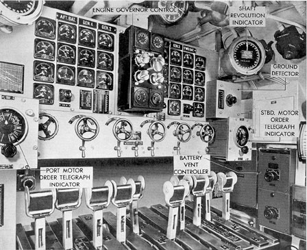
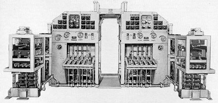
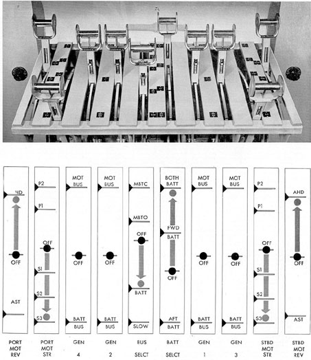
Figure 3-1. Front view of main control, installed.
39
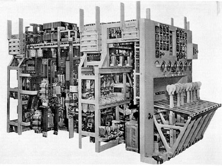
Figure 3-2. G.E. main control cubicle.
3A2. Split type main propulsion control
equipment. The split type control equipment
(Figure 3-5) is installed on some of the later
type submarines on which double armature,
slow speed, direct connected propulsion motors
are used. This equipment performs the same
functions as the single unit control cubicle, and
with the minor exceptions noted in Section 3B11
is operated in the same manner.
The two halves of the control panel are essentially
the same. Each half is mounted in a
steel frame which is joined to the other to form
a single structure and is shock mounted to the
hull. The starboard control panel consists of the
generator levers for the No. 1 and No. 3 generators,
starting and reversing levers for the starboard motor,
and a bus selector and forward
battery lever. The port control panel consists
of the generator levers for the No. 2 and No. 4
generators, starting and reversing levers for the
port motor, and a bus selector and after battery
lever.
3A3. Functions.The control equipment perform
the following functions:
1. Starts, stops, reverses, and regulates the
speed of the main motors for both surface and
submerged operation.
2. Provides for series, parallel, or series-parallel
connections of the motor armatures.
3. Provides for uniform speed control of
the main motors throughout the entire range of
propeller speed from about 38 rpm to 192 rpm
submerged, and to about 280 rpm on the surface.
4. Provides for operating the main motors
from one or both main storage batteries and
from any combination of the main generators.
5. Provides for charging one or both storage
batteries with main generators, individually
or in combination. Main generators not being
used for battery charging may be used for propulsion
power.
40
6. Provides for driving the starboard motors
from the starboard generators and the port
motors from the port generators entirely
independently of each other except for a common
excitation bus.
7. Provides for operation ahead on one
propeller shaft and astern on the other at any
speed within the designated operating range.
8. Provides, by means of shore connections,
for charging the main battery from shore or
tender.
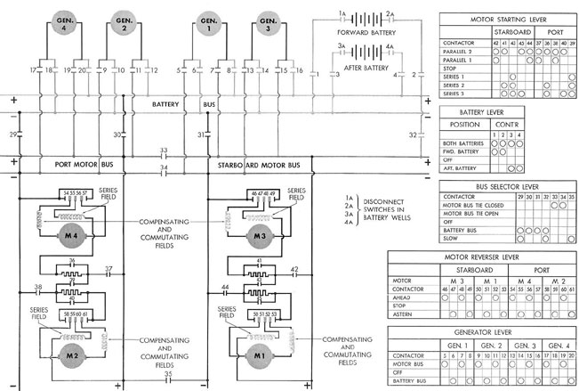
3A4. Simplified power circuit description.
a. The main control cubicle circuit (Figure
3-6) consists essentially of two buses, the motor
bus and the battery bus to which the main
power units are connected by means of their
associated contactors in order to provide the
various operating combinations. The motor bus
is the one to which the main motors are
connected for any of the running conditions by
means of their starting contactors.
The motor bus can be split for operation of
the motors on one side independently of the
other side (BUS TIE OPEN), closed for parallel
operation of both motor groups (BUS TIE
CLOSED), connected to the battery bus for
battery operation of the main motors (BATTERY
BUS), and lastly, for series operation of all
motors, the positive side of one motor bus can be
cross-connected to the negative side of the other
motor bus, so that by proper closing of the
motor contactors, all four motors can be placed
in series for slow speed operation on the battery
bus (SLOW).
Either or both batteries can be connected to
the battery bus by closing their respective
contactors which in turn are controlled by one
operating lever.
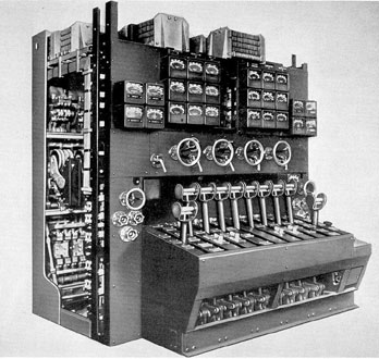
Figure 3-3. Cutler-Hammer main control cubicle.
41
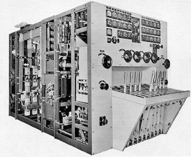
Figure 3-4. Westinghouse main control cubicle.
Each main generator has two sets of contactors
so arranged that only one set can be
closed at a time. One set when closed connects
its generator to the battery bus so that the main
battery can be charged from the generator. The
other set connects the generator to the motor
bus for driving the main motors. Associated with
the main motors are contactors for 1) connecting
the motors to the motor bus with the motors in
each group in either series or parallel, and with
the motors in series with their starting resistors;
and 2) for shorting out the resistors as the motors
come up to speed and the starting current
reduces. Also associated with the motors is a
switch group that provides for connecting the
armatures of the motors in a reverse direction
to operate the motors in the astern direction.
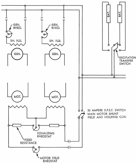
b. Excitation and control circuits. As
indicated in Figure 3-7, excitation power is
furnished from either the forward or after battery
through a two-pole, double throw switch provided
with a locking device for securing it in
the OPEN position or in either of its CLOSED
positions. This switch is connected to the battery
cables on the battery side of the battery contactors
in the control cubicle. The schematic
diagram shows the motor fields connected in
series. On some vessels, however, they are connected
in parallel.
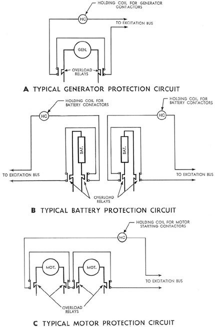
e. Protective circuits. Motor, generator,
and battery contactors are provided with
overload protection of the trip-free, holding coil
type. An overload relay is placed on each side
of each armature and each battery. All overload
relays associated with each group of contactors
are connected in series with a holding coil. The
holding coil is an electromagnet which, when
de-energized, allows the trip-free mechanism to
operate. For the description of this mechanism
see Section 3A14. The protective circuits are
shown in Figure 3-8.
42
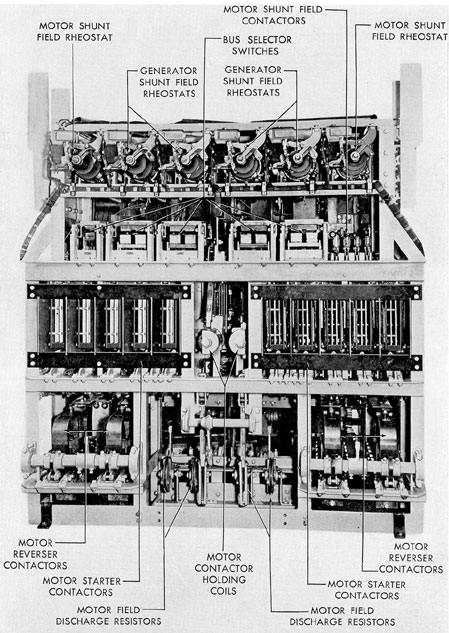
3A5. Principal parts. The principal parts of
the equipment are as follows:
1. One main propulsion control panel and
operating bench with necessary instruments,
rheostats, operating levers, etc.
2. One after contactor group comprising:
a. Port and starboard motor reversing
switches.
b. Port and starboard motor starting contactors.
c. Bus selector switches.
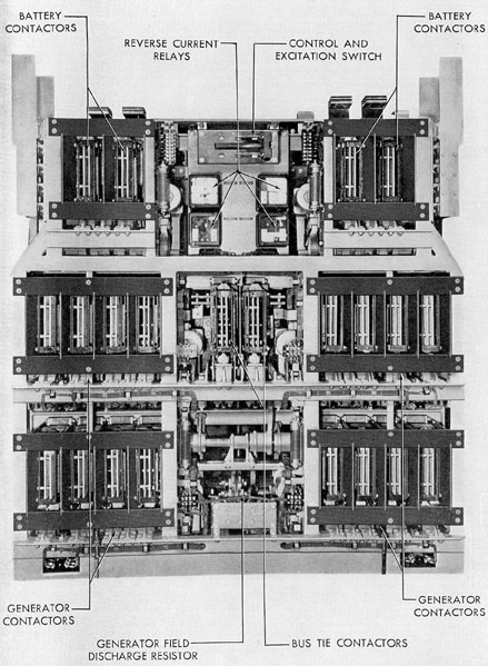
3. One forward contactor group comprising:
a. Port and starboard main generator contactors.
b. Forward and after battery contactors.
c. Motor bus tie contactors.
All parts are mounted in a number of steel
frames which are joined to form a unit. The
assembly is supported on rubber shock mounts
which are secured to the hull.
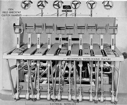
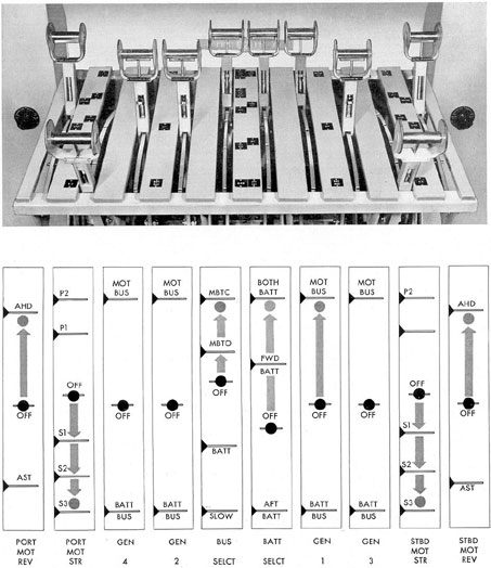
3A6. Operating levers. There are 10 levers
for the manual operation of the contactors in
the various switch groups. These levers are
provided with lock latches and are mechanically
connected to the contactor camshafts by a series
of bell cranks and rods. The purpose of the
levers is as follows:
a. Two reverser levers. These levers are
used to change the direction of rotation of the
main motors by reversing the current flow
through the armature. One lever is for the 2
starboard motors, and the other is for the 2 port
motors. Each lever has 3 positions, AHEAD,
OFF, and ASTERN.
b. Two starter levers. Each of the starter
levers, 1 for the 2 port and 1 for the 2 starboard
motors, has a STOP position and 5 operating
positions, SER. 1, SER. 2, SER. 3, PAR. 1, and
PAR. 2. The starter lever is used for cutting in
a resistance in series with the armature, thus
keeping the starting current down to a minimum.
As the motor picks up speed, the resistance can
be cut out of the circuit when the
armature is at running speed and the current
reaches a normal value, putting it across the
line voltage. The starter levers have 3 series
Figure 3-5. Split type main propulsion control cubicle.
43
Figure 3-6. Schematic wiring diagram of main propulsion control.
44
Figure 3-7. Excitation circuits.
positions and 2 parallel positions. The 2 motors
on each shaft are always in series with each
other when the starters are in any of the 3 series
positions, the voltage of the line being divided
between each of the motors. When the starters
are in either parallel position, the 2 motors on
each shaft are in parallel, each motor receiving
the full line voltage, The SER. 3 and PAR. 2
positions are the only running positions of the
starter levers. Since the starting resistances are
45
Figure 3-8. Protective circuits.
46
Figure 3-9. After-side view of G.E. after contactor group.
47
Figure 3-10. Rear view of G.E. control equipment.
48
designed to carry current for short periods only,
the starting levers should never be left in SER.
1, SER. 2, or PAR. 1 longer than is, necessary
for the current to decrease to normal.
c. Four generator levers. One lever is provided
for each of the 4 main generators. The
levers have an OFF position and 2 operating
positions, MOTOR BUS and BAT. BUS.
NOTE. On Westinghouse controls the operating
positions are GEN. BUS and BAT. BUS.
The function of these levers is to place any
desired generators on the battery bus for charging
the batteries, or any one or all of the generators
on the motor buses for propulsion. An
extra mechanical latch on each lever prevents
accidental movement from the OFF position.
d. One battery selector lever. This lever
has an OFF position and 3 operating positions,
AFT. BAT., FWD. BAT., and BOTH BAT.
Placing the lever in the AFT. BAT. position will
place the after battery on the battery bus.
Placing it on the FWD. BAT. position will place
the forward battery on the battery bus. In the
BOTH BAT. position, both batteries are in
parallel with each other and on the battery
bus. The battery bus is a common connection
which is supplied with current from either one
or both batteries and which in turn supplies
current to the motor bus for motor propulsion
when the bus selector is in the battery position.
In addition, any desired generators may be
placed on the battery bus to charge either one
or both batteries as desired. When the battery
bus is used only for charging, it is necessary to
have only the battery selector and the charging
generator on the battery bus; the bus selector
can be in the OFF position.
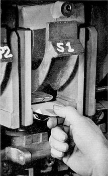
Figure 3-11. Operating levers.
49
e. One bus selector lever. The bus selector has
5 positions: BUS TIE CLOSED, BUS
TIE OPEN, OFF, BAT. BUS, and SLOW. The
functions of this lever are to connect the port
and starboard motor buses, to connect the
battery bus with the motor bus, and to close the
necessary contactors to operate all four motors
in series.
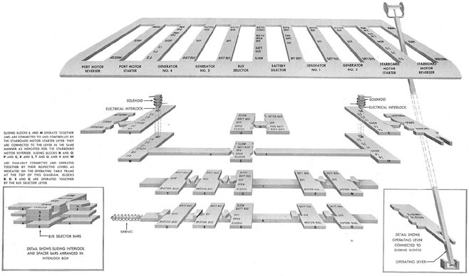
3A7. Mechanical and electrical interlocks.
The 10 operating levers have notched steel bars
attached to them and mechanically interlocked
with each other by slide bars. In addition, an
electrical interlock is provided on each starter
lever. This interlock consists of a solenoid whose
circuit is completed by cam-operated contacts
attached to the shaft of the field rheostat
handwheel. The resulting interlocking arrangement
of the operating levers is as follows:
1. A motor starter lever cannot be moved
from the STOP position unless the corresponding
motor field rheostat is in at least 75 percent
full field position (electrical interlock).
2. The reverser lever cannot be moved unless
the corresponding motor starter lever is in
the STOP position.
3. The battery lever cannot be moved if
the bus selector lever is in the SLOW or BAT.
BUS position except that it may be moved between
the FWD. BAT. and BOTH BAT. positions at any time.
4. The bus selector lever cannot be moved
unless both motor starter levers are in the STOP
position, except that the bus selector lever can
be moved between the MOTOR BUS-BUS
TIE OPEN and MOTOR BUS-BUS TIE
CLOSED positions at any time. The motor
starting levers cannot be moved when the bus
selector lever is in the OFF position.
5. A generator lever cannot be moved from
the OFF position to the MOTOR BUS position
unless the bus selector is in the OFF position.
CAUTION. If one generator is already in
the MOTOR BUS position, any other can be
thrown at will. Hence this interlocking arrangement
does not prevent the operator from placing
a dead generator on a live motor or battery bus
and seriously damaging the machine.
NOTE. On Cutler-Hammer and Westinghouse equipment
this interlocking function is
not present.
6. The auxiliary latch must be lifted before
a generator lever can be thrown to the
MOTOR BUS or BAT. BUS position. To operate
a lever with an auxiliary latch requires the
use of both hands, the object being to make the
operator realize the importance of the step and
cause him to think before he makes a particular
selection.
7. The bus selector lever cannot be thrown
to the BAT. BUS or SLOW position unless all
generator levers are in the OFF or BAT. BUS
position, nor can any generator lever be thrown
to the MOTOR BUS position if the bus selector
is in the BAT. BUS or SLOW position.
3A8. Overload relays. Each battery, motor,
and generator is protected against short circuit
and overload by means of overload relays connected
as shown in Figure 3-8. The overload
relay contacts open when the current exceeds a
certain value, thus de-energizing the holding coil
and permitting the contactors in the overloaded
circuit to open.
The relays are provided with adjustable,
calibrated tension springs for the purpose
of adjusting the current at which the relays open.
Since the relays are of the instantaneous acting
type, they must be set rather high to prevent
tripping due to current peaks which may occur
during starting and maneuvering. The battery
relay is usually set for 12,000 to 14,000 amperes.
The generator and motor relays are usually set
for 10,000 to 13,000 amperes. For specific calibrations
of the various relays refer to the manufacturer's
instruction book.
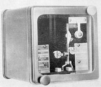
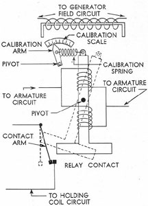
3A9. Reverse current protection. A reverse
current relay (Figures 3-13 and 3-14) is provided
for each main generator to protect it and
its driving engine when charging batteries. These
relays are adjusted to operate at a low reverse
current value. In the event of reverse current
flow (current flowing from battery to generator)
of sufficient value, the relay contacts open, thus
deenergizing the holding coil circuit and causing
the generator contactors to open. The relays normally
are set to operate at 300
50
Figure 3-12. Diagram of Interlocking arrangement.
51
amperes and 250 volts. These relays are nonoperative
if the generator is supplying power to the
motor bus.
CAUTION. These relays do not act in sufficient time
to prevent damage to a generator if
it is accidentally connected to the battery when
Figure 3-13. Main generator reverse current relay, closed.
Figure 3-14. Schematic diagram of main generator reverse current relay.
it is not rotating, or if its field is not energized.
3A10. Field discharge resistors. The field
discharge resistors connected across each generator
and motor shunt field serve to limit the inductive
voltage rise across the field during opening of the
field switch. The resistors used on
Cutler-Hammer and Westinghouse equipment
consist of wire wound resistors connected across
the field terminals just before the field circuit is
opened. General Electric employs "Thyrite"
(trade name) units (Figure 3-15) which are
composed of a ceramic material, having very
high resistance at low voltages and low resistance
at high voltages. They are permanently
connected across the field terminals. In both
types of installation, the energy of the discharging
field is dissipated in the resistors in the form
of heat, thereby protecting the field coils from
the high voltage that results from the sudden
opening of an inductive circuit.
Figure 3-15. GE "Thyrite"field discharge resistor.
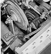
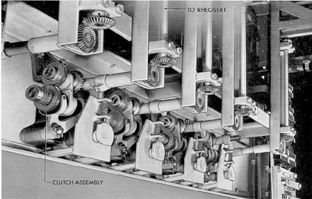
3A11. Motor and generator field rheostats.
The 2 motor rheostats port and starboard, and
the 4 main generator rheostats are of similar design.
General Electric employs a fixed commutator type, the
individual bars of the commutator being connected to taps
on the field resistor.
The contact brush is rotated through bevel gearing
by a handwheel on the front of the panel.
Each rheostat has 90 steps of resistance.
52
Included on each of the 4 generator rheostat-operating
shafts are 2 cam-operated generator
field contactors, the cams being so arranged that
the contactors open after all resistance has been
inserted in the field circuit. The motor field
rheostats also have 2 cam-operated contactors.
One, which closes in the full field position, serves
to bypass the rheostat. The other, which closes
at 75 percent full field position, completes a
circuit to an electrical interlock on the motor
starting lever. Westinghouse and Cutler-Hammer
rheostats are of the face plate type design,
employing a contact arm which travels over a
number of contact points mounted on a face
plate, with the resistance bank mounted behind
the face plate. The Westinghouse and Cutler-Hammer
generator rheostats are not equipped
with field contactors.
Whenever 2 or more main generators are
operated in parallel, their field rheostats can be
clutched together and driven from any one of
the handwheels. However, the Cutler-Hammer
clutching mechanism is so arranged that the
rheostats cannot be tied together until they are
in identical positions, whereas the arrangement
on General Electric and Westinghouse permits
clutching of the rheostats regardless of their
relative positions.
Figure 3-16. Field rheostat, G.E. commutator type.
Figure 3-17. G.E. field rheostat clutch mechanism.
53
3A12. Vernier rheostats. Two load-balancing rheostats,
sometimes called vernier rheostats,
are provided, one for the two port and one for
the two starboard motors. By acting to
strengthen the field of one motor and at the
same time weaken the field of the other motor,
they provide a manual means of equalizing the
load between the two motors on one shaft when
they are operating in parallel.
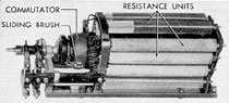
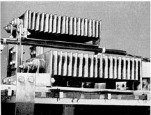
3A13. Motor starting resistors. One starting
resistor is provided for each motor armature.
These resistor units consist of steel straps or
cast grids made of an alloy containing mainly
nickel, copper, and iron. The capacity of the
resistors is sufficient to carry the full motor
armature starting current for approximately 1
minute when the motor starting lever is in SER.
1 position, plus 1 minute in the SER. 2 position,
and 1 minute in the PAR. 1 position, provided
the motors are operated for 1 minute in the
SER. 3 connection when moving from SER. 2
to PAR. 1.
The resistors will stand a duty cycle of 2
minutes on, 1 minute off, and 1 minute on with
900 amperes flowing through the resistors, and
not exceed 390 degree C during this cycle. These
Figure 3-18. G.E. main motor starting resistors.
resistors are located overhead between the forward
and after contactor groups.
3A14. Contactors. All contactors that may
be required to operate under load are provided
with arc chutes and magnetic blowout coils for
circuit interrupting duty. All contactors, with
the exception of the motor bus-bus tie contacts
and the contactors which short out the starting
resistance have, incorporated in their operating
mechanism, a trip-free feature that allows the
contactor to open independently of camshaft
position. After such opening, due to overload,
reverse current, and so forth, the camshaft must
be returned to the OFF position to reset the trip
mechanism before the contactor can again be
closed.
3A15. Ground detector equipment. The
ground detector equipment provided on the main
control panel consists essentially of the following
parts:
1. A double-scale voltmeter with a range
from 0 volts to 500 volts on both sides of the
center.
2. A rotary selector switch for selecting
the particular circuit to be tested on motors or
generators.
3. A battery selector switch for selecting
the particular battery or polarity to be tested,
either positive or negative alone, or both.
4. A resistor and push-button switch connected in
parallel with the voltmeter. The purpose of this circuit
is to lower the effective resistance of the voltmeter
circuit to one-tenth
of its regular value. It is provided primarily to
increase the accuracy of measurement of low insulation
resistance that is encountered on main
power cables when they are carrying full load
current continuously.
Instructions for the operation of this equipment
are given in Section 3C4.
54
Figure 3-19. G.E. main motor starting contactors, arc chutes removed.
55
B. OPERATION
3B1. General. While all contactors are designed
to break any normal operating current,
contactor maintenance can be kept at a minimum
by reducing, whenever possible, the current broken
by the contactor to its lowest
amount before opening the contactor.
When moving the operating levers from one
position to another, the operation should be
firm, fast, and positive. Slow or hesitant operation
will draw out sustained arcs between the
arc tips, thereby causing excessive burning.
However, this does not mean that they should
be slammed from one position to another as
this will cause rapid wear of the parts. One
exception to this rule should be noted: When
moving the motor-starting lever from a SERIES
position to a PARALLEL position, a momentary
positive stop is made in the STOP position
before moving into the PARALLEL position.
This allows time for the series contactor arc to
collapse before the parallel contactors are closed.
This stop is also necessary when returning from
the PARALLEL position to the SERIES position.
CAUTION. If this precaution is not observed the
supply may be effectively short circuited and the
resulting fire will certainly damage the control
equipment. This casualty has
occurred several times in submarines on patrol,
putting the control cubicle out of commission.
In operating the starting lever in a sequence
of positions, the motor ammeters indicate a
sudden high current as each position is reached,
but, as the speed of the motor increases, this
current decreases to a more or less steady armature
current, indicated by a steady position of
the motor ammeter pointer. The most successful
operation of the motor control is obtained
by waiting for a steady motor ammeter indication
while in one lever position before moving
the lever to the following position.
The normal operating position of the starter
levers for SLOW operation (that is, with the
bus selector in the SLOW position) is in the
SER. 3 position. If the starter levers are moved
to the PAR. 1 and PAR. 2 positions, thereby
increasing the propeller speed and motor load,
the series selector contactor will be overloaded.
If greater speed than that obtained in the SLOW
position is desired, the selector lever should be
placed in the BAT. BUS position and the starter
lever in the SER. 3 position.
CAUTION. The holding coil control switch
should be opened slowly to allow for collapse
of the induced voltage in the coils. Sudden opening
of the switch may cause an induced voltage
that will break down the circuit insulation so
that repair or replacement will be necessary.
When using the same number of generators
on each side, the bus selector lever should be in
the MOTOR BUS TIE OPEN position, thereby
disconnecting the port and starboard motor
buses. For one-generator or three-generator
operation, it should be in the MOTOR BUS TIE
CLOSED position in order to supply equally
both port and starboard motors, and for balancing
the generator loads. For two-generator
or four-generator operation, when the generators
are divided equally between port and starboard,
the bus selector lever may be in either the
CLOSED or OPEN position. The OPEN position is
preferred because it tends to prevent an
electrical fire from spreading from one side of
the cubicle to the other and permits independent
control of the motors and generators on each
side. Further, opening of contactors under
overload on one side will not affect the operation of
the other side.
In parallel operation of main generators,
with the generator field rheostats mechanically
clutched together for common operation, a
mechanical interlock on each clutch handle
prevents the turning of any rheostat far enough to
disconnect its field. On older type GE controls
this is accomplished by a switch on the clutch
that bypasses the field contactors. The clutch
cannot be engaged for combined operation if the
field contactors are open.
It is possible for the bus selector lever to
be moved from the BUS TIE OPEN to the
BUS TIE CLOSED position at any time,
thereby possibly throwing generator bus voltage
across nonrotating motors or generators. Before
moving the BUS selector lever from the
BUS TIE OPEN to BUS TIE CLOSED position, make the
following checks:
56
1. Check to see that the voltmeters for all
generators that are connected to the motor bus
read the same voltage. If not, either adjust the
generator rheostats until they do or disconnect
from the motor bus.
2. Check to see that if the generator levers
in one side (port or starboard) are not in the
MOTOR BUS position that the starter lever on
that side (port or starboard) is in the STOP
position.
For one- or two-generator operation always
operate motors in series. For three- or
four-generator operation always operate motors in
parallel.
3B2. Optimum operating conditions. Detailed
instructions for starting and operating the
propulsion system in various combinations are
given in the manufacturer's instruction book for
the vessel. Due to the slight differences among
the interlock systems for the several classes of
submarines, it is not possible to give a single set
of operating instructions that will cover all systems
correctly. In order to get the best in performance
and reliability out of the propulsion
system, there are a few fundamental points
which must be observed. They apply equally to
all types of electric drive submarines, although
the exact values of current, voltage, speed, and
so forth, must be obtained from the manufacturer's
instruction book.
3B3. Adjustment of generator field current.
In general, the best engine operation requires
that the generator be run more slowly as the
power output becomes less. The power is equal
to the product of the voltage and the current
produced by the generator. Since the voltage
depends on the speed and field current, if the
field current remains constant and the speed is
reduced as the load is lessened, the generator
voltage will decrease in proportion to the load.
This condition requires that the armature current
remain constant for all loads. Since the
major part of the losses is due to the armature
current and since the ventilation becomes less
as the speed is reduced, the net result is
overheating of the generator. Therefore, the best
results are obtained when the generator is run at
the maximum speed compatible with good engine
performance and also at maximum field
current. At full load, the generator
should always be run at, or slightly above, rated voltages,
but not below.
3B4. Adjustment of motor field current.
While submerged, the motor field strength is
the only control over the speed of the vessel
(aside from the connection of the armatures in
various combinations of series and parallel). On
the other hand, when operating from the generators,
the fields of the motors are adjusted to
obtain the desired output from the engines.
When starting and maneuvering, the field should
always be kept at full strength to increase the
available torque and reduce current peaks. For
steady operations, the motor field current should
be adjusted to give the desired load on the generators
being used. It varies, depending on the
number of engines used for propulsion. For example,
with one engine on propulsion with the
two motors on each side in series, it is necessary
to weaken the motor field to about 80 percent
of normal to load the generator to its full rated
load. With two engines, one on each side, and
the two motors on each side in series, the motor
fields must be weakened still more, (to approximately
62 1/2 percent of normal) to fully load
the two engines. For three generators on propulsion,
with all four motors connected in parallel, the motor
fields must be increased to approximately 110 percent of
normal to obtain a
full load on the engines. For four generators,
full load should be obtained with normal full
field on the motors. However, under conditions
of foul hull and so forth, full load may be
reached at a propeller speed lower than designated,
in which case more than the normal field
will be required. This condition is unfavorable
to the motors as it has the effect of reducing
the series field, causing poor parallel operation.
Therefore, should full load be reached at a propeller
speed less than that designated, operation
should be restricted and when used, the voltage
of the system should be made as high as possible by
increasing the generator field current.
3B5. Maneuvering. Maneuvering should always be
performed on an even number of generators divided
between the two sides. This
makes it possible to control the two shafts entirely
independently of each other and also to
control the speed by generator field control
which makes much smoother operation possible.
57
When planning to use three generators, it is
easier to start on two and add the third later.
Maneuvering on the battery may be used whenever
the maneuvers are not to last long or when
maximum power is required immediately. When
maneuvering on the battery, care should be
taken to allow current peaks to die down to a
steady state before proceeding to the next
position on the starting lever.
3B6. Reversing. A quick reversal can be
made either from the generators or the battery.
For a generator reversal, it is desirable to have
an even number of generators so that if an overload
relay is tripped, power to only one screw
would be affected. Reversal from the battery
may be used when only one engine is in use at
the time or for other reasons. On some vessels
a reversal on the battery can be made faster
than on the generators, but on others, which
require the generators to be taken off the motor
bus first, it takes approximately the same time.
Maximum braking effect will be obtained when
the current is held to a maximum (approximately
150 to 200 percent) and the transitions
when no power is put out, are made as fast as
possible. The recommended procedure for reversal
on the engines is as follows:
1.
Turn motor field rheostat to maximum.
2.
Reduce engine speed to minimum.
3.
Turn generator field rheostat to minimum but do not open.
4.
Move starter lever to STOP.
5.
Move reverser lever to BACK.
6.
Move starter lever to SER. 1 and then to SER. 2 and SER. 3.
7.
Increase engine speed.
8.
Increase generator speed.
All steps should be made smoothly with
the current maintained as close to maximum as
possible. If too much power is used in reversing,
the propeller will cavitate and no increase in
braking effort will be obtained.
3B7. Adding a generator to a live bus.
Whenever a generator is added to a live bus,
its voltage should be adjusted to slightly above
that of the bus. This will prevent reverse current
from flowing to the generator. When adding
a generator to the motor bus, its speed and load
should be equalized with the others on the bus
and its rheostat and governor control clutched
to the others. As the new generator heats up, it
will drop part of its load and necessitate declutching
and readjustment of the rheostat.
3B8. Propulsion from auxiliary generator.
On a few vessels it is possible to put the 300-kw
auxiliary generator on propulsion entirely free
of the battery. However, on most vessels this is
not possible. The auxiliary generator can, however,
be used for propulsion without raising the
battery voltage to the undesirable values which
result in excessive evaporation. This is done as
follows:
1. Start the auxiliary generator and connect to the
battery. Adjust its voltage to 260 to
270 volts.
2. Start the motors from the battery and
run in series. Adjust the motor field rheostat to
give the desired shaft speed, being careful not
to exceed the current rating of the auxiliary
generator.
3. Make final adjustments of voltage with
the auxiliary generator field rheostat, and of
current with the motor field rheostat.
The above procedure is based on the assumption
that the battery is fully charged. If
the battery is being charged, the voltage must
necessarily be determined by the state of the
battery charge. It should be noted that the
auxiliary generator must carry all auxiliary
power as well as propulsion, and the current,
therefore, should be read from the auxiliary
generator ammeter rather than from the ammeters
on the control cubicle.
3B9. Battery charging with a propulsion
generator. Any propulsion generator not
being used for propulsion may be placed
on battery charge. It is necessary only to adjust its
voltage slightly above battery voltage and throw
its lever to BAT. BUS. The charging current is
adjusted with the generator field rheostat. One
battery may be charged independently of the
other by placing the battery selector lever in
the position for the battery to be charged.
CAUTION. Make certain that the auxiliary
power bus tie does not parallel the two batteries when they are not paralleled in the
propulsion control cubicle. The auxiliary power bus
tie should never be closed except when all
58
auxiliary power is being obtained from one battery,
the auxiliary generator, or the shore connection.
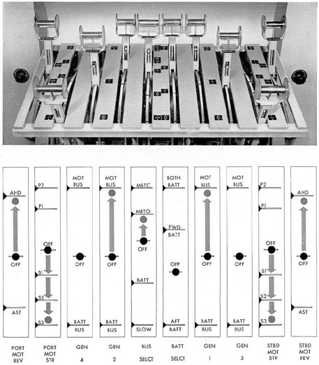
3B10. Operation.In Figures 3-20 to 3-27
are shown, for General Electric single unit propulsion
control equipment, the movements and
final position of the operating levers for various
operating conditions noted in the titles. These
positions will be similar in the other manufacturers'
equipment but the specific instruction
book for the equipment in use must be consulted
for the exact operating procedure before attempting
operation, as the sequence of handling
of the control levers varies with the different
makes of equipment.
Figure 3-20. Position of operating levers for one-generator operation.
59
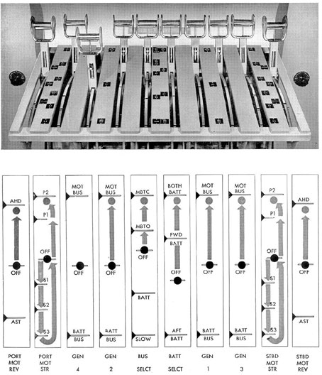
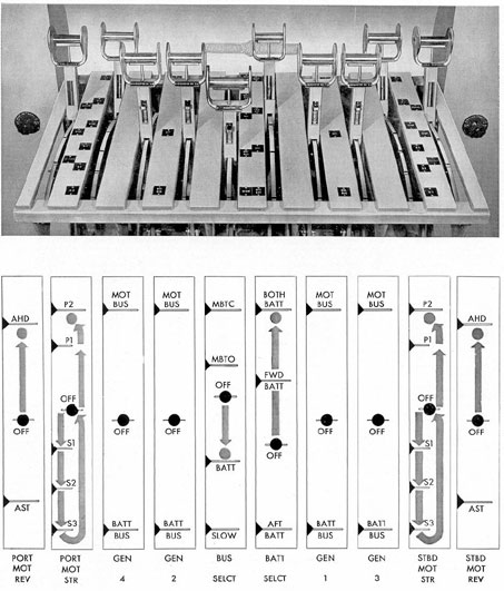
Figure 3-21. Position of operating levers for two-generator operation.
60
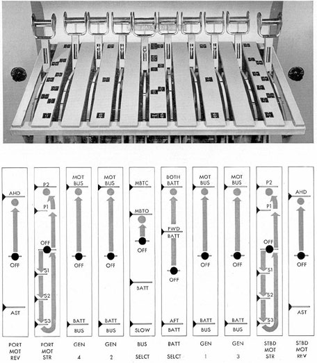
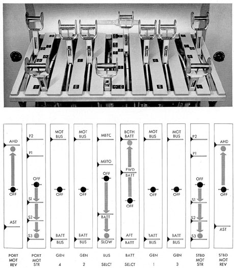
Figure 3-22. Position of operating levers for three-generator operation.
61
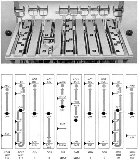
Figure 3-23. Position of operating levers for four-generator operation.
62
Figure 3-24. Position of operating levers when charging batteries with one generator and with the other generators supplying propulsion power.
63
Figure 3-25. Position of operating levers for battery operation of 1/3 and 2/3 speed.
64
Figure 3-26. Position of operating levers for battery operation at standard and full speed.
65
Figure 3-27. Position of operating levers for battery operation at slow speed.
66
3B11. Split type propulsion control. In general,
the split type propulsion control is operated
in the same manner as the unit type. Due
to the duplication of bus selector and battery
levers, both must be moved to the same position
to operate with bus tie closed and in dead slow
speed.
3B12. Safety precautions. The following are
the more important safety precautions to be
observed in handling this equipment:
1. Do not enter the main control cubicle
when the buses are energized.
2. Do not leave the motor and generator
field circuits energized when the machines are
not in service except for the purpose of keeping
the machines from 5 degree to 10 degree F warmer than
the surrounding air in order to prevent
condensation of moisture on the windings. Even then
the field current should never be more than is
necessary for that purpose.
3. Do not operate the motors and generators
with field currents in excess of the recommended values.
4. Never place a generator on a live bus
without first checking to see that its voltage is
equal to the voltage of the bus.
5. If the lubricating oil pressure on the
motors and reduction gears fails, stop the
motors immediately and ascertain the cause of the
failure.
6. Never release the control lever latches
unless preparatory to moving to a new position.
Make certain that a lever engages the slot in its
new position.
7. Do not operate the machinery with the
safety devices or interlocks disconnected.
8. Do not advance the motor starting levers
to the next position until the armature current
has dropped to a reasonable value.
9. Make frequent inspections to insure that
no tools or loose objects are inside the control
cubicle or in such a position that they can fall
into it or any part of the operating gear.
10. Whenever possible, deenergize the control
cubicle and make frequent inspections for
loose nuts and bolts and other connections.
11. Never operate the motors or generators
at greater than rated armature current.
C. MAINTENANCE
3C1. Inspection and lubrication. The amount
of servicing and replacement of parts of the
control equipment depends upon the frequency
of and care exercised in regular inspection. In
normal service, the equipment should be inspected
at approximately monthly intervals.
Particular emphasis should be placed on keeping
contacts, cams, and mechanism free from
dirt and other foreign matter. Such parts as
bolts, nuts, and screws should be checked for
tightness. Bearing surfaces must be kept properly
lubricated. A drop or two of oil applied on
control linkages at the time of regular inspection
will provide sufficient lubrication. Excessive
lubrication is harmful; oil or grease should
be used sparingly.
3C2. Contactors. It is essential that the
contacts of all contactors, switches, and relays
be kept clean. Arcing contacts and arc boxes
that are badly burned should be cleaned or replaced.
In an emergency, the are chute of a frequently
operated working contactor may be
interchanged with that of a contactor subjected
to less arcing. When contact tips are found to
be badly burned or making poor contact, they
should be dressed with a fine file. Do not use
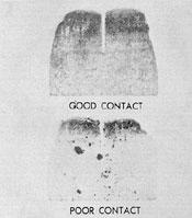
emery or sandpaper. Contacts can be checked
by laying a strip of carbon paper against a
clean sheet of thin paper and inserting these
strips between the contact surfaces. Closing the
contacts will leave on the paper a carbon impression
that will indicate the approximate condition of the
contact surfaces (Figures 3-28 and
3-29).
67
Figure 3-28. Checking contacts with carbon paper.
Figure 3-29. Carbon impressions of contact surfaces.
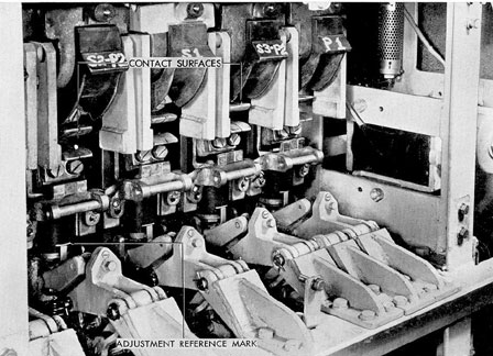
3C3. Motor reverser and bus selector
switches.The springs of the selector and reverser
switches exert a pressure of several hundred pounds
to hold the contacts together when
the switch is thrown. The normal contact gap
and wipe as specified by the manufacturer
should be maintained within 1/64th of an inch.
Installation conditions may reduce the tip wipe
slightly, but the switch will operate successfully
as long as a positive wipe is obtained.
Contacts should be examined to see that
foreign material has not accumulated on the
silver surfaces. Surfaces should be kept aligned so
that a carbon paper impression will show that at
least 60 percent of the contact area, well-distributed
over the entire surface, is making contact. Use
only a fine file for dressing the surfaces. These
switches function only as circuit-selector
switches and are never required to make
or break their contacts with current flowing.
The wear of the silver contact surfaces is
therefore negligible and the contacts should require
replacement only after long periods of service.
Since these switches are of double throw
design, it is necessary that both the upper and
lower contact gaps and wipes be equal. If they
are not equal, and all switch units operated by
a common camshaft show the same irregularity
in the gap and wipe dimensions of the upper
and lower contacts, the difficulty is probably
caused by a loose cam or by slippage of the
moving contact assembly on the vertical
supports. Contacts should not be shimmed to
correct for irregular gaps or wipes.
3C4. Ground detection.A ground detector
system is installed in the propulsion control
cubicle to test for grounds on a number of
circuits. It consists essentially of a zero-center
ground detector voltmeter with selector switches
so arranged that the voltmeter can first be
connected from ground to the positive side of a
circuit and then from ground to the negative
side of the circuit. If the voltmeter reads zero in
both cases the circuit is not grounded. If one
side of the circuit has a dead, or very low
resistance ground, the voltmeter will read zero
when connected from ground to the grounded
side, and will read full circuit voltage (voltage
68
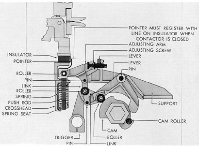
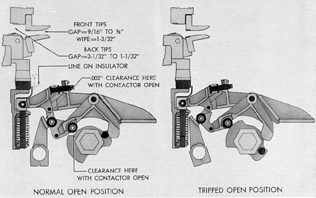
Figure 3-30. Operating mechanism of G.E. motor, generator, and battery contactors, CLOSED position.
Figure 3-31. Operating mechanism of G.E. motor, generator, and battery contactors, OPEN position.
69
from positive to negative side) when connected
from ground to the ungrounded side of the circuit.
If the ground has an appreciable resistance
or if it occurs at a point on the circuit where
the potential is intermediate between the potentials
of positive and negative sides of the circuit, the
ground detector voltmeter readings will
be less than full circuit voltage. The ground
detector system can be used to detect grounds on
the battery or machines while they are in operation,
and on machines while they are idle.
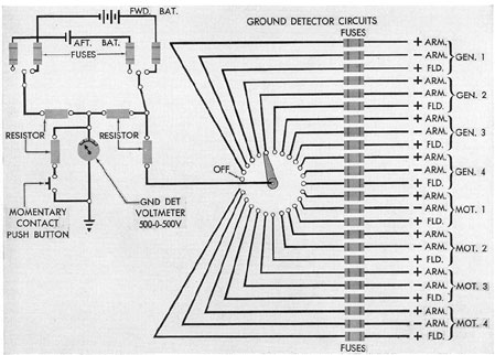
a. Battery grounds. 1. To detect battery
grounds, turn the machinery ground detector
selector switch to OFF. A study of Figure 3-32
shows that the battery selector switch can be
used to connect the ground detector voltmeter
to each battery in each of the following ways:
a) From ground to positive battery terminal.
b) From ground to negative battery terminal.
c) From ground to the center point joining two
equal high resistances connected in series
across the positive and negative battery
terminals. The potential at the center point
between the two resistances is obviously the same
as the potential at the center point of the
battery.
2. When connected according to c) above,
the voltmeter will deflect in one direction for a
ground or grounds on the positive cable leg or
positive half of the battery; and in the opposite
direction for grounds on the other half of the
system. There will be no deflection of the voltmeter
if the battery is grounded at the center;
or if the battery and cables are symmetrically
grounded on both sides of the center; or even if
the system is unsymmetrically grounded on both
sides of the center if certain relations exist
between the positions of the grounds and their
resistances. Consequently, when the voltmeter
is connected to the battery in this way, a
voltmeter deflection definitely establishes the
Figure 3-32. Ground defector wiring diagram.
70
existence of a ground on the battery or cables, but
the absence of a deflection furnishes no assurance
that grounds are absent.
3. A conclusive test for the presence or absence
of grounds is made by noting Vp, the
voltmeter reading when connected to the positive
battery terminal, and Vn, the voltmeter reading
when connected to the negative battery terminal.
These are the ground detector voltmeter readings when
it is connected according to a) and b)
above. If both Vp and Vn are
equal to zero,
there are no grounds. If either is different from
zero, or if both are different from zero, there is
at least one ground on the battery or on cables
or equipment connected to the battery.
a. On the newer submarines, grounds on
the battery alone, when disconnected from its
cables by opening the battery disconnect
switches (main and auxiliary power and emergency lights) in the battery tank, can be detected and measured by using the voltmeter
mounted on the individual cell voltmeter panel
(see Section 5A9).
b. Test on machines in operation. To detect
grounds on machines in operation, turn the
ground detector battery selector switch to OFF,
or in some installations to TEST LIVE CIRCUIT.
Turn the machinery selector switch to
connect the ground detector voltmeter from
ground, first to one side of the machine and then
to the other side. If the ground detector reads
zero in both cases, there are no grounds. If
either reading is different from zero, or if both
are, there is a ground on the machine or in the
circuit to which it is connected. It may be noted
in Figure 3-32 that the ground detector voltmeter
can be connected to either the positive or
the negative side of the armatures, but to only
one side of the field circuits. A zero reading on
one side of a field circuit is not sufficient to show
that no part of the circuit is grounded, but
further test on the machine when it is idle will
check this point.
c. Test on machines when idle. To make
a test on machines that are idle, first turn the
machinery selector switch to OFF, then turn
the battery ground detector selector switch to
TEST DEAD CIRCUIT. This connects two
high resistances in series across one battery and
connects the ground detector voltmeter from
ground to the center point between the two
resistances. There may be a small deflection of
the voltmeter if the battery and its circuits have
a high resistance ground or grounds, or there
may be no deflection. The test on machinery can
be made in either case. To do this, turn the
machinery selector switch from OFF to the machine
or circuit which is to be tested. If the
ground detector voltmeter reads the same as it
did when the selector switch was at OFF, neither
side of the machine or circuit tested is grounded.
If the reading is not the same there is a ground.
CAUTION. Always turn all ground detector selector
switches to OFF when testing
has been completed. Furthermore, never attempt
to use more than one ground detector system
at a time. There are several installed but they
should be used one at a time.
3C5. Use of ground detector voltmeter to
measure insulation resistance. A megger is
not suitable for measuring the resistance
of battery grounds because a battery, unlike
a generator, cannot be deenergized. The ground
detector voltmeter system, however, can be used
not only to detect grounds but also to measure
the insulation resistance to ground from batteries
or from energized equipment or circuits. The
insulation resistance to ground is found by using
the equation:
R = Rv ((E/(Vp - Vn) - 1)
In this equation, E represents the voltage across
either a motor, generator, or battery as the case
may be; Vp and Vn represent
the reading of the
ground detector voltmeter when connected to
the positive and negative terminals of the motor,
generator, or battery; Rv is always the resistance
of the ground detector voltmeter.
Consider, for example, a submarine with a
50,000-ohm ground detector voltmeter on the
submarine control cubicle. With the battery
connected to the control cubicle, the battery
voltage E was observed to be 243 volts, and the
readings of the ground detector voltmeter were
from each leg to ground Vp = 10,
and Vn =
192. The insulation resistance to ground from
the complete circuit including the battery and
71
the cables from the battery to the control cubicle
was therefore:
R = 50,000 ((243/202) - 1) = 10,000 ohms
This was a low value of insulation resistance and
required further investigation. The battery was
isolated from the cables by opening the battery
disconnect switches, and additional measurements
were made on the battery alone by using
the ground detector voltmeter on the individual
cell voltmeter panel. The ground detector voltmeter
installed on this panel had a resistance of
30,000 ohms. The battery voltage E was 243
volts, while Vp and Vn
were 9.2 and 10.6 volts
respectively. The insulation resistance to ground
from the battery alone was, therefore:
R = 30,000 ((243/19.8) - 1) = 338,000 ohms
The cause of the low resistance observed at the
control cubicle was, therefore, not the battery,
but the battery cables. Tests made on these
with a megger showed that one leg had a low
resistance and this was responsible for the low
resistance found for the complete circuit.
Similarly, by use of the above formula, resistance
to ground of any generator or motor
may be measured while it is operating. It must
be remembered that measurements by this
method while machinery is energized and
operating represent the combined resistance to
ground of all machinery connected to the same
circuit. Whenever a low value is obtained, the
units must be completely isolated and individual
readings taken of insulation on each component
in order to locate the affected part.
The accuracy obtained in measuring insulation
resistance with a ground detector voltmeter
depends upon the accuracy and resistance
of the voltmeter used and the value of the
insulation resistance being measured. Insulation
resistances that are either very large or very small
as compared to the voltmeter resistance are determined
only approximately. Insulation resistances not too
greatly different from the voltmeter resistance can
be measured with considerable accuracy.
Very accurate measurements of insulation
resistance can be made when needed by
deenergizing the circuit and using an insulation
resistance tester. The chief advantages of the
ground detector voltmeter are that it can be
used to measure insulation resistance at any time
a circuit is in use, and that it furnishes a means
of making a continuous check on insulation
resistance.