A. ROTARY CONVERTER AND CONSTANT FREQUENCY CONTROL UNIT
12A1. Description. The purpose of the constant
frequency control unit is to control the
speed of rotation of a rotary converter, primary
120-volt d.c., secondary 115-volt, 60-cycle, a.c.,
and maintain the frequency of the output at
exactly 60 cycles for operation of the log and
shaft revolution indicator system.
There are two types of constant frequency
control units in use, one made by the Pitometer
Log Corporation and the other by the Electric
Tachometer Corporation. Both units operate on
the principle of an electrically driven tuning
fork, and are similar in construction. The 60-cycle
tuning fork is the prime source of constant
frequency.
The rotary converter converts 120-volt direct
current to 115-volt, 60-cycle alternating current.
This converter, together with the frequency
control unit, supplies the constant frequency
60-cycle current necessary for the operation of the
synchronous motor in the propeller shaft revolution
indicators.
The converter is compound wound with a
separate field lead brought out for connection to
the rheostat in the constant frequency control
unit. The machine is of drip-proof construction
arranged for overhead mounting.
The converter has a 4-pole armature designed for
rotation at 1800 rpm. The field is of
4-pole cast iron construction. Another winding
on the field is connected to an external resistance.
A centrifugal governor is connected in such
a manner that with no external field resistance
it regulates the speed of the inverted rotary
converter
to about 1775 rpm. When the speed of the
inverted rotary converter is increased to 1800
rpm by means of field resistance, the contacts of
the governor remain closed and the speed control
rests with the external resistance in the constant
frequency control unit.
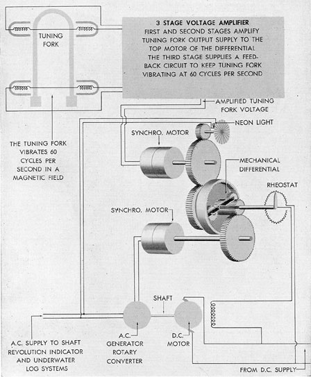
12A2. Operation of Electric Tachometer
Corporation type unit. The controlled frequency
power is obtained from the a.c. output
slip rings of a rotary converter and energizes the
lower of 2 synchronous motors in the frequency
control unit. One side of a mechanical differential
is driven in synchronous relation with the
converter output frequency by this lower synchronous
motor. The other side of the differential is driven
in a reverse direction at constant
speed by the top synchronous motor. Constant
frequency power for this top motor is obtained
from a vacuum tube amplifier and its associated
tuning fork which is adjusted to vibrate at
exactly 60 cycles. Thus, the 60-cycle tuning
fork is the prime source of constant frequency
which it generates in coils nearest the weighted
ends and impresses on the amplifying tube. The
fork and amplifier work together; the tuning
fork vibrates independently at its own natural
frequency and the amplifier keeps the fork vibrating
by feeding back some output power.
Most of the amplifier power output goes to rotate
the top motor at a constant speed corresponding to
the frequency of the fork.
A spider arm is operated by the action of
the differential and this arm operates a rheostat
to control the field current of the inverted rotary
converter. The action which takes place is
as follows:
When the top and lower motors are running at the
same speed, there is no motion of
the differential spider arm. This condition exists
only when the converter output frequency is the
same as, the fork frequency. If the converter falls
below synchronous speed, the decreased speed
of the lower motor and its half of the differential
starts the spider arm revolving. The spider
arm turns the arm of the rheostat. The change
in position of the rheostat arm changes the
converter field current so that the speed and
output
frequency of the converter are restored to
synchronism with the tuning fork. The frequency
of the converter output is thus effectively locked
160
Figure 12-1. Schematic diagram of constant frequency control unit.
in synchronism with the tuning fork frequency.
This condition is true in spite of changes in load
on the converter, temperature-resistance changes
in the windings, or +- 10 percent variation in
the d.c. voltage supply to the converter.
A stroboscope disk, driven by the top motor
at tuning fork frequency, gives visual indication
of a gain or loss in converter speed. Normally
the radial lines of the stroboscope disk appear
to be stationary because the flashes of light from
161
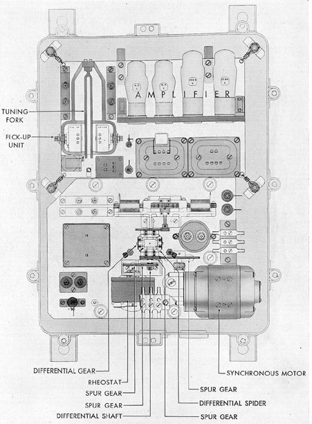
Figure 12-2. Frequency control unit, Pitometer Log Corporation type.
162
the stroboscope lamp connected to the output
frequency are in synchronous relation to the
constant speed of the disk. If the converter gains
or loses, the change in the rate of flashes creates
the illusion of turning of the disk. At the
same time, the differential spider arm does
actually turn, due to the changed speed of the
lower motor. If for any reason the apparatus
fails to correct the change in speed, an alarm is
energized to show that the unit has lost control.
The stroboscope disk is intended as a relative
check of converter and fork frequency. A clock is
provided as a means of checking the absolute
or real value of the converter frequency. When
the generated output frequency is 60 cycles, the
hand of the clock makes 1 revolution per
minute. When the stroboscope disk shows that the
converter is in synchronism, the clock serves as
a check on the fork. The operation of the Pitometer
Log Corporation control unit is identical,
except that the tuning fork is started by a magnet
and clapper controlled by the line switch.
The units are described in detail in the
manufacturer's instruction book.
12A3. Maintenance. It is necessary that the
brushes and commutator of the converter be
kept clean and the brushes set for minimum
sparking under normal load. Detailed maintenance
instructions for bearings, gears, and tubes
may be found in the manufacturer's instruction
book.
B. UNDERWATER LOG SYSTEM
12B1. Description. The underwater log system consists
of the equipment required for indicating the speed
of the submarine and the
distance traveled through the water. Each of
the various types of underwater log systems in
service requires a rodmeter which projects out
through the pressure hull of the submarine, and
mechanisms for converting into a speed indication
the differences between the dynamic pressure of the water caused by the forward motion
of the ship, and the surrounding static pressure.
Each of the systems also has a mechanism for
integrating speed with respect to time to indicate
the total distance traveled. The system requires
115-volt, 60-cycle, single-phase, alternating
current for operation and is designated as
circuit Y.
The mechanical and electrical units of the
underwater log system are actuated by water
pressure obtained through the rodmeter. The
rodmeter has 2 passages and extends into the
water a distance of about 3 feet. Being located
at the forward part of the ship, it is in relatively
smooth-flowing water, since the water at this
point is least affected by the movement of the
ship or by the turbulence created by action of
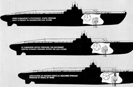
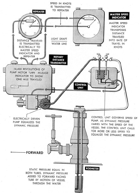
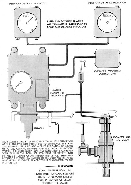
the propellers. When the ship is at rest, the
water pressure is equal in both passages of
the rodmeter and is due only to the weight of the
water above the system. This pressure is known
as static pressure. As the ship moves forward,
the movement creates additional pressure in the
forward passage of the rodmeter. This added
pressure is known as dynamic pressure. The
difference between these pressures is the actuating
force that operates the system.
The method used to convert the dynamic
pressure into indications of speed and distance
differs as follows in the three underwater log
systems used in service.
1. Rotary balance type underwater log
system. An underwater log system of the rotary
balance type employs a rotary balance unit
consisting of an automatically controlled
motor-driven centrifugal pump that develops a
pressure to oppose the dynamic pressure from the
rodmeter. The pump is connected to the dynamic
passage of the rodmeter and to the inner part of
a sensitive bellows assembly. The outside of the
bellows assembly is connected to the static
passage of the rodmeter. Pressure differences
between the passages in the bellows cause it to
expand or contract, thereby moving a rod which
in turn actuates a motor driving a rheostat.
This rheostat controls the speed of the pump
motor and is known as the transtat assembly.
Any increase or decrease in dynamic pressure
caused by variation of the ship's speed causes a
movement of the transtat arm, resulting in a
change in speed of rotation of the pump drive
motor. The speed of rotation of the pump motor
therefore, is always proportional to the speed
of the ship through the water.
163
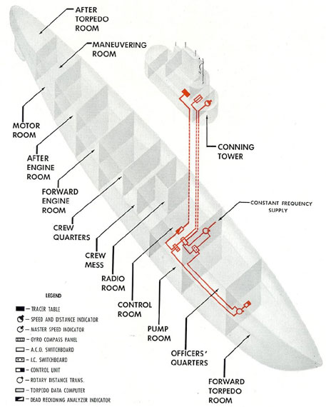
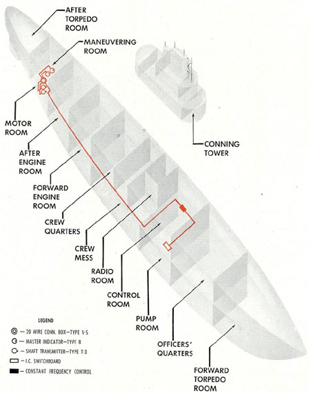
Figure 12-3. Schematic diagram of underwater log system.
164
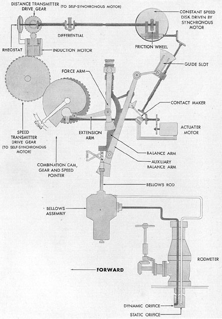
Figure 12-4. Elementary diagram showing fundamental principle of operation of underwater log system.
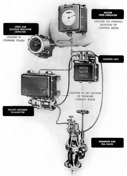
The pump motor shaft is geared to a selsyn
transmitter by means of which rotary motion
proportional to the speed of the ship is conveyed
to 2 selsyn indicators. One of these indicators is
geared to a mechanical counter in the master
speed indicator which registers the total distance
traveled in miles. This same selsyn indicator,
through suitable gearing and in conjunction
with a time element derived from the constant
frequency a.c. supply, operates a pointer that
shows the speed of the ship in knots. The other
selsyn indicator driven by the pump motor
transmitter operates a mechanical counter in the
remote speed and distance instruments. Remote
indications of the ship's speed are transmitted
by a selsyn transmitter in the master speed indicator driven by the miles per hour pointer
shaft. Speed input to fire control and navigational
equipment is obtained from this same
transmitter.
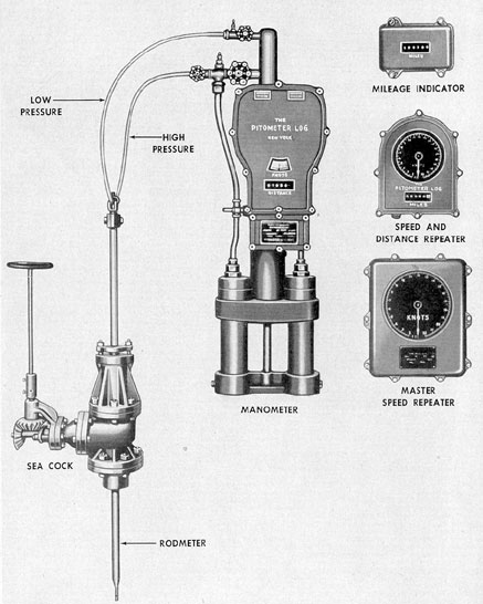
2. Mercury manometer type underwater
log system. The mercury manometer type of
underwater log system installed in some older
submarines uses a mercury manometer instead
of bellows as the means of actuating the mechanism
for indicating the speed and distance
traveled.
The mercury manometer consists of 2 tubes
containing mercury. They are connected at the
top to the dynamic side of the rodmeter. A pipe
line connects the 2 manometer tubes at the bottom
ends and has an opening in the center to
allow mercury to enter a chamber containing a
float. The static pressure is admitted into the
top of this float chamber. Any change in dynamic
pressure causes a change in the level of
the mercury in the float chamber, thus causing
the float to position itself accordingly. A rack
attached to the top of the float drives a gear
coupled in turn to the main shaft of the
transmitter mechanism.
The transmitter mechanism is the master
speed and distance indicator as well as the
transmitter for remote indications. The main
shaft of the transmitter mechanism is directly
connected to the master speed dial. Thus, the
master speed dial is positioned directly by the
movement of the mercury in the float chamber
165
Figure 12-5. Schematic diagram of rotary balance type underwater log system.
166
Figure 12-6. Arrangement of units of rotary balance type underwater log system.
167
Figure 12-7. Pitometer log mercury manometer type units.
168
and indicates the correct speed without any
electrical connection. The speed indication is
transmitted to speed repeaters in the control
room and conning tower by means of selsyn
units.
Distance indication is obtained from the
speed element by means of a mechanical integrator
using constant frequency input as a time
element. It is transmitted to the control room
and conning tower through selsyn units.
3. Bendix type underwater log system. The
Bendix type underwater log system is actuated
by the expansion and contraction of a bellows
similar to the assembly used in the rotary balance
type system. When a change in dynamic
pressure occurs, the bellows move a diaphragm
to which is attached a bellows rod. Movement
of the bellows rod actuates a main balance arm
that carries a contact maker. Any movement of
the main balance arm and its associated contact
maker closes the circuit to an actuator motor.
This actuator motor in turn drives a combination
cam and gear in the center of which is
mounted the speed pointer.
The main balance arm is attached by a
coil spring to another arm, known as the main
force arm. Approximately at the midpoint of
the main force arm is an extension with a cam
roller on its extreme end. This cam roller at all
times rides on the cam part of the cam and gear
combination driven by the actuator motor. The
resulting pressure of the cam on the cam roller
causes the main force arm to swing in a direction
opposite to the original movement of the
main balance arm. This motion tends to return
the main balance arm to the neutral position
due to the spring tension between the two arms.
At this point the actuator motor contact is
broken, the motor stops, and the combination
cam and gear with its attached speed pointer
remains in its assumed position.
The auxiliary balance arm is connected to
the main balance arm by means of a spring
and swings independently of it. It is positioned
by the setting of the adjustment on the guide
slot and by means of the lead screw driven by
the actuator motor. Tension on the auxiliary
balance arm spring tends to aid the main force
arm in returning to the NEUTRAL position.
The function of this auxiliary balance arm and
connecting spring is to permit setting of a
calibration correction that is dependent upon the
speed and to affect the neutral point at which
the main balance arm settles for each speed.
The driving gear for the speed transmitter
is in mesh with the gear of the cam and gear
combination driven by the actuator motor. The
transmitter is a conventional selsyn unit
connected to speed indicators in the conning tower
and control room.
Distance indication is obtained from the
master speed indicator by means of a mechanical
integrator using constant frequency input as
a time element and is transmitted to the control
room and conning tower through selsyn units.
12B2. Operation. After the rodmeter is lowered,
the complete system is placed in operation
by turning switches marked 1Y, 2Y, and 3Y,
located on the I.C. switchboard, to the ON position. When switch 1Y is closed, speed indications are transmitted to the conning
tower and
control room. This switch also completes the
circuit for the speed input to the torpedo data
computer, gyrocompass, and dead reckoning indicator.
Switch 2Y completes the circuit from the
115-volt a.c. bus to the selsyn transmitter for
distance indications in the conning tower and
control room.
Switch 3Y completes the circuit from the
controlled frequency a.c. bus to the synchronous
motor (time element) in the master instrument
in the forward torpedo room or control room.
12B3. Maintenance. Adjustment or repairs
should not be attempted without reference to
the manufacturer's instruction book for specific
instructions.
NOTE. Complete and detailed information on all
phases of the theory, operation, and
maintenance of the log may be found in
Submarine Underwater Log Systems, NavPers
16168.
169
Figure 12-8. Schematic arrangement of Bendix bellows type log.
C. PROPELLER SHAFT REVOLUTION INDICATOR
AND COUNTER SYSTEM
12C1. Description. a. General. The purpose
of the propeller shaft revolution indicator and
counter system is to transmit indications of
propeller rpm and total revolutions from the
propeller shafts to the control station in the
maneuvering room. The system is designated as
circuit K and consists essentially of the following
parts:
1. Transmitters located in the motor room
and geared to the propeller shafts.
2. Indicators in the maneuvering room at
the control station. These indicators have a
pointer to indicate rpm, a counter to indicate
total shaft revolutions, and a backing signal.
The system operates on a constant frequency power
supply of 115-volt, 60-cycle,
single-phase, alternating current obtained from
the constant frequency control unit through
fused switches on the I.C. switchboard.
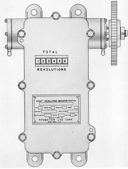
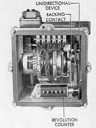
b. Transmitters. Each of the transmitters
in the motor room consists of a conventional
selsyn transmitter geared to its respective propeller
shaft, which transmits rpm indications to
its allied indicator in the maneuvering room. In
the watertight cases containing the transmitter
units is a simple mechanical counter. It is chain
driven by the transmitter shaft and indicates
total shaft revolutions. The transmitters are
designed to operate in only one direction and
carry a unidirectional device that maintains a
constant direction of rotation regardless of the
direction of rotation of the propeller shafts.
The visual backing signal in the maneuvering room
indicator is actuated by a pair of contacts
located at the top of the unidirectional
device. Normally, these contacts are open and
no signal is indicated. When the propellers rotate
in the reverse direction, the arm carrying
the reversing gears in the unidirectional device
closes the contacts, thereby actuating a magnet
which pulls into view a white letter B in a red
field signifying back rotation of the propeller
shaft.
Essentially, the transmitter units of the two
types of shaft revolution indicator and counter
systems in service are the same. The indicator
units, however, while employing the same principle
of operation, differ considerably in construction
and detail.
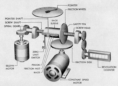
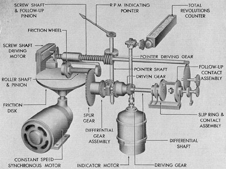
c. Indicator units. 1. Electric Tachometer
Corporation type. The selsyn indicator (motor)
(Figure 12-12) actuated by the transmitter
in the motor room carries spiral gears on its
shaft. These gears drive a screw shaft in a
constant direction and at a speed proportional to
the speed of the propeller shaft. Threaded on
the screw shaft is a nut to which is attached a
friction wheel. The rim of this friction wheel is
always in contact with a friction disk below it.
The friction disk, driven at a constant speed of
96 rpm by a synchronous motor, is pressed
against the edge of the friction wheel by a spring.
Thus, when the friction wheel is in the center of
the friction disk, it is held stationary, but, as it
is moved outward by the rotation of the screw
shaft in the nut, it begins to rotate. The speed
at which it rotates is dependent upon its position
on the face of the friction disk. As long as
this speed is less than the speed of the screw
shaft, the wheel and nut continue to move outward
until the wheel reaches a spot on the friction disk
where its speed is equal to the speed
of the screw shaft. At this point there is no
longer any tendency for the nut and friction
wheel to move along the screw shaft, and the
wheel rides on a circle of radius exactly proportional
to the propeller shaft speed.
The rotating nut carries with it, on ball
bearings, a rack sleeve that is restrained from
turning. Along the side of this sleeve is a rack
gear meshing with a small pinion on the shaft
carrying the pointer. The pointer comes to rest
at a position determined by the finally balanced
position of the friction wheel, and thus indicates
on a properly divided scale, the rpm of the
propeller shaft.
The indicator unit also contains a mechanical
revolution counter. The counter is gear-driven
off the end of the screw shaft and indicates
total shaft revolutions.
172
Figure 12-10. Schematic diagram of propeller shaft revolution Indicator and counter system.
173
Figure 12-11. Pitometer log type of shaft revolution transmitter.
174
Figure 12-12. Schematic arrangement of Electric Tachometer Corporation type indicator and counter system.
Figure 12-13. Top view of propeller shaft revolution
transmitter, Electric Tachometer Corporation type
with cover removed.
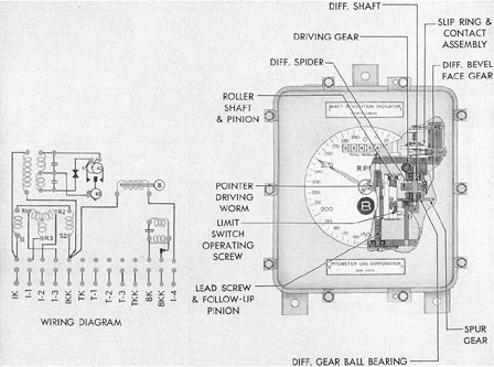
2. Pitometer log type. The Pitometer log
type indicator (Figure 12-15) operates on the
same principle as the Electric Tachometer type.
The essential difference in construction is that
the indicator shaft drives one half of a differential
gear assembly and the friction disk drives
the other half. The screw shaft is rotated by a
separate reversible motor and moves the friction
wheel across the face of the friction disk in
a manner similar to that of the Electric Tachometer
instrument. The friction disk is driven
by a constant speed synchronous motor at a
speed of 100 rpm. The screw shaft driving motor
is started, stopped, or reversed by a set of contacts
mounted on the shaft that carries the pinion gear
of the differential assembly. When the
indicator motor begins to rotate its half of the
differential, a movement of the pinion gear results
because the other half of the differential
is stopped, or is rotating very slowly. Movement
of the pinion gear closes the contacts for the
screw shaft driving motor, causing the friction
wheel assembly driving the other half of the
175
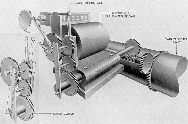
Figure 12-14 Schematic arrangement of shaft revolution transmitter.
176
differential to move outward across the friction
disk. This movement of the friction wheel away
from the center of the friction disk causes the
wheel and its associated differential gear to rotate
at a constantly increasing speed. This speed
continues to increase until it is equal to the
speed of the other half of the differential. When
the point is reached at which there is no more
turning effect imparted to the pinion gear, the
contacts operated by the pinion gear shaft open
and the screw shaft driving motor stops. The
friction wheel assembly is then positioned on
the friction disk and remains there until a change
in propeller shaft speed again causes a mechanical
unbalance of the differential.
The pointer shaft is directly geared to the
screw shaft and gives a steady indication of
propeller rpm on a properly divided scale.
The indicator motor also drives, through
gearing, a mechanical counter which indicates
total shaft revolutions.
12C2. Operation. The system is placed in
operation by turning switches marked 1K and
2K on the I.C. switchboard to the ON position.
These switches energize the circuits to the
starboard and port transmitters. Switches 8K1 and
8K2, also on the I.C. switchboard, must be
turned to the ON position in order to energize
the circuits from the constant frequency bus to
the starboard and port synchronous motors
which drive the friction disks.
NOTE. If the synchronous motor circuits
are not energized, there will be no force to
prevent the friction wheel from traveling to the
extreme outer edge of the friction disk, thus
causing the instrument to indicate maximum
rpm regardless of the speed of the propeller
shaft.
12C3. Maintenance. When the propeller
shafts are stopped, the friction wheel should not
Figure 12-15. Schematic arrangement of Pitometer
log type propeller shaft revolution
indicator and counter system.
177
Figure 12-16. Details and wiring diagram of Pitometer
log type master indicator.
be in such a position as to indicate zero rpm.
It should indicate between 2 and 4 rpm. In order
to indicate zero, the friction wheel would have
to come to rest at the exact center of the friction
disk, and the revolution of the disk would
impart a twisting motion to the rim of the friction
wheel. The resulting friction would grind
a flat spot on the rim of the wheel and a depression
in the center of the disk.
No adjustments, lubrication, or repair
should be attempted without reference to the
detailed instructions contained in the manufacturer's
instruction book.
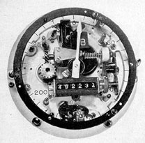
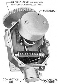
12C4. Propeller revolution indicator system, magneto
type. Late design submarines
employ a very simple revolution indicator system
based on the magneto voltmeter principle
(see Figures 12-18 and 12-19). Geared to each
propeller shaft is a small, enclosed, permanent
magnet magneto of the 2-wire d.c. type which
transmits a direct current proportional to the
Figure 12-17. Shaft revolution indicator, Electric
Tachometer Corporation type, with face removed.
rotational speed of the shaft. A mechanical
counter indicating only total ahead turns is
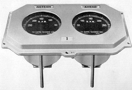
built into the same housing as the magneto.
The indicator for each shaft consists of 2
voltmeters mounted in a simple housing on each
side of the control cubicle, one being calibrated
for and reading ahead speed, and the other reading
astern speed for that shaft. The system resembles the
engine tachometer system. It requires no external
source of energy, and connecting it to any source
of power will damage the
instrument.