4A1. Description. Modern submarine diesel
engines are started by admitting compressed air
into the engine cylinders at a pressure capable
of turning over the engine. This process is continued until the pistons have built up sufficient
compression heat to cause combustion. The
pressure used in air starting systems is approximately from 250 to 500 psi.
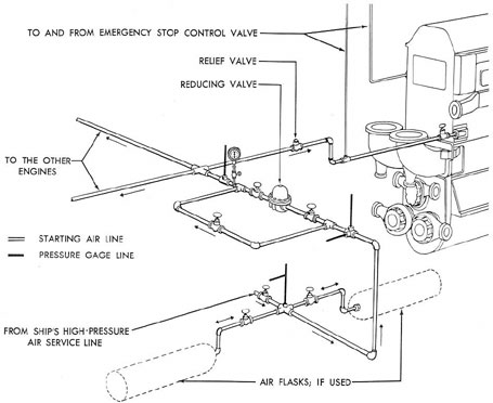
4A2. Source of starting air. Starting air
comes directly from the ship's high-pressure air
service line in which pressures up to 3,000 psi
are normally maintained, or from starting air
flasks which are included in some systems for
the purpose of storing starting air. In either
instance, the air on the way to the engine, must
pass through a pressure reducing valve which
reduces the higher pressure to the operating
pressure required to start a particular engine.
A relief valve is installed in the line between
the reducing valve and the engine. This relief
valve is normally set to open at 25 to 50 pounds
in excess of the air starting pressure. Thus, if
the air pressure leaving the reducing valve is too
high, the relief valve will protect the engine by
releasing air in excess of the value for which it
is set and permit only air at approximately the
proper pressure to reach the engine cylinders.
Figure 4-1. Typical starting air piping system.
81
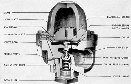
Figure 4-2. Grove regulator valve.
4A3. Pressure regulating valve. The pressure reducing valve is a Grove regulator (Figure
4-2) in which compressed air, sealed in a dome,
furnishes the regulating pressure that actuates
the valve. Thus the compressed air in the dome
performs the same function as a spring used in
a conventional type of valve.
The dome is tightly secured to the valve
body which is separated into an upper (low
pressure outlet) and a lower (high-pressure inlet ) chamber by the main valve. At the top of
the valve stem is another chamber which contains a rubber diaphragm and a metal diaphragm plate. This chamber has an opening
leading to the low-pressure outlet chamber.
When the outlet pressure drops below the
pressure in the dome, air in the dome forces the
diaphragm and the diaphragm plate down on
the valve stein. This opens the valve and permits high-pressure air to pass the valve seat
into the low-pressure outlet and into the space
under the diaphragm. As soon as the pressure
under the diaphragm is equal to that in the
dome, the diaphragm returns to its normal
position and the valve is forced shut by the high-pressure air acting on the valve head. When air
is being used from the low-pressure side of the
regulator, this action is continuous and very
rapid in order to maintain the correct pressure
on the discharge side.
High-pressure air entering the valve body
is filtered through a screen to prevent the entrance of any particles of dirt which would prevent the valve from seating properly. The screen
is held in position around the space under the
valve head by the threaded valve seat bushing.
The screen should be removed and cleaned periodically to insure an unrestricted flow of air,
If particles of dirt are permitted to remain and
accumulate in the screen, the high air pressure
may tear the screen from its position and force
it into the working parts, causing damage to the
valve seat.
Air for the original charging of the dome
is obtained from the high-pressure chamber of
the valve body by opening two needle valves,
As soon as the desired pressure, as indicated by
the gage on the discharge side of the regulator,
82
Figure 4-3. Engine starting control levers, GM.
is reached, the needle valves must be closed. The
dome will then regulate and maintain the discharge of air at that pressure.
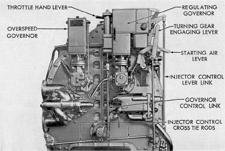
4A4. Starting the GM engine. The GM engine is started by means of two control levers,
the throttle hand lever and the air starter hand
valve lever. The throttle hand lever has three
positions, STOP, START, and RUN. In the
STOP, or central, position, the fuel supply to
the cylinders is cut off. Moving the lever toward
the START position rotates the fuel pump
plunger toward the full pump position. The
RUN position gives the Woodward regulating
governor unrestricted control of the engine. The
air starter hand valve lever has only two positions, OPEN and CLOSED.
Prior to starting the engine, and with the
throttle hand lever on the STOP position, the
engine is turned over several times by opening
the air starter hand valve with the cylinder test
valves open. This insures that there are no obstructions to prevent the starting of the engine.
The cylinder test valves are then closed. The
engine is started by holding the throttle hand
lever in the START position and opening the
air starter hand valve. The engine should start
after a few revolutions if the fuel supply has
been primed and is not airbound. As soon as the
engine is firing, the air starter hand valve is
closed and the speed of the engine adjusted by
means of the throttle hand lever. As soon as the
governor oil pump has built up a working pressure, the throttle lever is shifted to the RUN position. This shifts the engine to governor control.
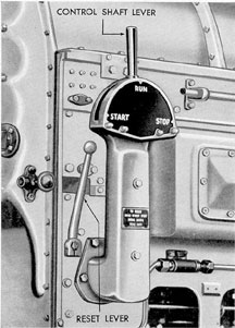
4A5. Starting the F-M engine. The F-M engine is started by means of a control shaft lever.
This lever has three positions, START, STOP,
and RUN. In the STOP position, the fuel cutout
cam on the control shaft moves the fuel injection pump control rod to the no fuel position.
When the lever is in the START position, the
air start control valve is opened, allowing air
starting of the engine. In the RUN position, the
engine is under full governor control.
83
To start the engine, the governor is set at
idling speed and the control shaft lever moved
from the STOP position to the RUN position
and then toward the START position. When
the lever passes the RUN position, the fuel injection pump control rod is unlocked. When the
lever reaches the START position, air starting
air begins to enter the cylinders. As soon as the
engine is firing, the control shaft lever should be
shifted to RUN. This allows full governor control and closes the air start control valve.
B. GENERAL MOTORS ENGINE AIR STARTING SYSTEM
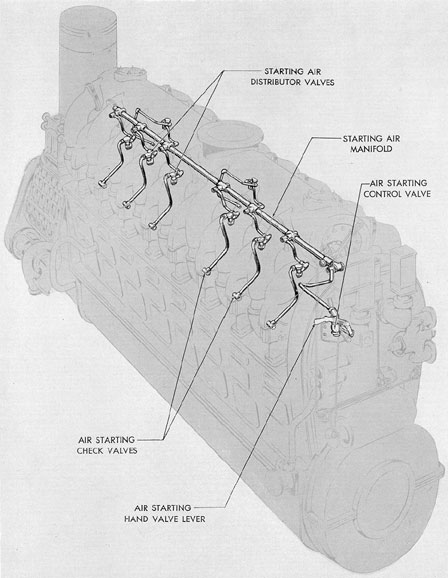
4B1. Description. The engine air starting system used on GM engines is known as the separate distributor type, the starting air distributor
valve being a separate unit for each cylinder.
Each distributor valve is individually operated
by its cam on the camshaft. Eight of the 16
cylinders, six in one bank and two in the other,
are air started, but all of the cylinder heads in
both banks are equipped with air starter check
valves so as to maintain full interchangeability.
On the cylinders that are not air started, the air
inlet opening is sealed with a removable plug.
4B2. Operation. Air is supplied to the air
starting hand control valve from the air supply
line. The air starting control valve is opened by
a hand lever, thereby admitting air to the starting
air manifold. The starting air manifold is a
steel pipe extending the full length of the engine
and is located on the top deck of the engine below
the exhaust manifold. It is connected
by air lines to each of the starting air distributor valves.
The distributor valves are
opened in engine cylinder firing order by their
cams on the camshafts, admitting air into the
lines that connect each distributor valve to its
air starting check valve. As the distributor valve
admits air into the line leading to the air starting
check valve, the pressure opens the check
valve, thereby admitting air into the combustion chamber;
The air pressure moves the pistons and
turns the crankshaft until there is sufficient compression for combustion. Combustion pressure
and exhaust gases are kept from backing into
the air starting system by the check valves. As
soon as the engine is firing, the hand lever is
released, and spring pressure closes the air starting control valve. This shuts off the supply of
starting air to the engine.
4B3. Air starting hand control valve. The
air starting hand control valve is mounted on a
bracket bolted to the camshaft drive cover near
the hand control lever. It is a poppet type valve,
opened manually by a lever and closed by a
spring. A plug in the valve body holds the spring
against the valve head. The valve stem guide is
a bronze bushing pressed into the body. A spring
and head placed over the valve stem, where it
projects from the body, return the hand lever to
the valve's closed position. The hand lever and
the operating lever stop are keyed to a shaft in
the bracket.
A safety device prevents opening of the air
starting control valve while the engine jacking
gear is engaged.
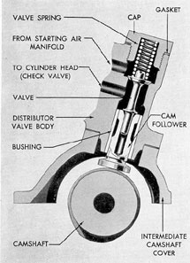
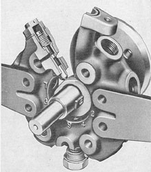
4B4. Air starting distributor valve. Each
Figure 4-4. Control shaft lever, F-M.
84
Figure 4-5. GM engine air starting system.
85
cylinder having air starting is equipped with an
air starting distributor valve.
The air starting distributor valves, or timing valves as they are sometimes called, are of
the poppet type with forged steel bodies that
bolt to the camshaft intermediate covers. The
valve is held closed by spring pressure bearing
against the top of the valve and is guided in the
hollow end of a cam follower which rides on the
camshaft air starting cam. The cam follower is
guided in a bronze bushing pressed into the
valve body. A lockpin locates the cam follower
in the body.
When cam action opens the valve, starting
air passes from the air manifold through a
chamber in the valve body above the valve head
into a line leading to the air starting check valve
in the cylinder head. The cam action opens the
valves in the proper firing sequence. The cam
follower is lubricated by oil splashed from the
cam pocket by the cam.
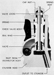
4B5. Air starting check valve. The air starting check valve is a poppet type valve located
Figure 4-6. Air starting distributor valve, GM.
in the cylinder head. The valve body fits into a
recess in the cylinder head and is held in place
by a cap nut that screws into the cylinder head
and ears on the top of the valve body. The
valve body contains the valve seat and serves
as a valve stem guide. Air is prevented from
leaking to the outside of the valve body by a
synthetic rubber seal ring located above the
inlet port. The valve face makes direct contact
with the valve seat in the valve body. The valve
is held closed by a spring over the valve stem,
bearing against the valve body and also against
a spring seat locked to the valve stem. The
spring seat is locked in position on the valve
stem with two half-round seat locks that fit into
a groove in the valve stem. The valve opens into
a small chamber with a short, open passage to
the cylinder.
When the air starting distributor valve admits air into the line leading to the air starting
check valve, the air passes into a chamber
around the valve seat. The pressure of this air
opens the check valve and allows the air to pass
into the cylinder, moving the piston. When the
Figure 4-7. Air starting check valve, GM.
86
air starting distributor valve closes, the pressure
drops and spring tension closes the air starting
check valve.
When combustion begins, the air starting
check valve remains closed, as the pressure in
the combustion chamber is greater than the
pressure of the starting air that actuates the
check valve. This prevents exhaust gases and
combustion pressures from backing up into the
air starting system.
4B6. Maintenance. Line connections and
valves of the air starting system should be
maintained in a closely fitting, airtight, operating condition. Leakage at the air starting
distributor valve is likely to result in starting failure. Leakage at the air starting check valve will
start scoring of the valve seat, a condition that
will become progressively worse and impair the
operation of the valve.
Valve seats should be inspected at least at
every major overhaul period, and the valves
ground and reseated if necessary. The air starting distributor valve on the GM engines should
have a clearance of between 0.010 and 0.020
inch measured between the cam and the cam
follower. If the cam follower cannot be ground
off sufficiently to bring the clearance within
these limits, a new assembly should be installed.
C. FAIRBANKS-MORSE ENGINE AIR STARTING SYSTEM
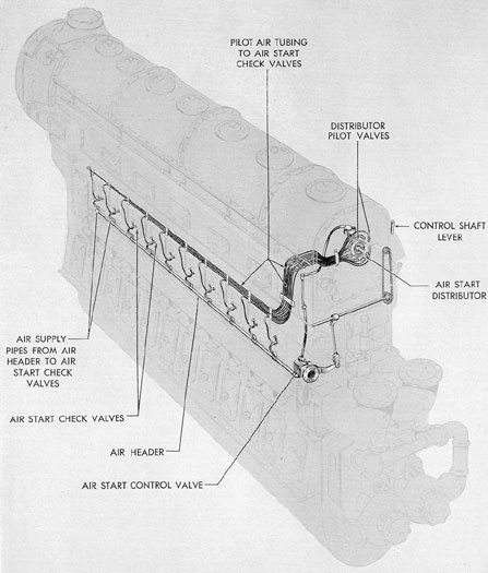
4C1. Description. The F-M engine air starting system consists of the starting air piping and
the engine starting mechanism. The engine starting mechanism includes the air start control
valve, air start distributor, the starting air
header, the pilot air tubing, and the air start
check valves at the individual cylinders. This
type of air starting system has a distributor
block consisting of several pilot valves which
provide actuating or pilot air to regulate the
opening of the air start check valves at the
proper moment, allowing the starting air itself
to enter the cylinders. All cylinders of the submarine type F-M engines are air started.
4C2. Operation. The air starting control
valve is manually operated from the engine control lever. When the engine control lever is set
at START, a lever linkage opens the air starting control valve, admitting air from the supply
line to the air starting main header. This header
is connected by branch lines to the air starting
check valves at each cylinder. A branch line
from the air starting control valve supplies pilot
air to the distributor. This distributor includes
one pilot air valve for each cylinder in the engine. These pilot valves are arranged radially
and in engine firing order around the group distributor camshaft (sometimes referred to as the
cam stub shaft). A spring holds each valve out
of contact with the cam when the engine is running on its own power. But when air enters the
distributor from the air start control valve, the
air pressure overcomes the spring tension and
forces each pilot valve plunger down into contact with the cam. Regardless of where the
camshaft has stopped, one pilot air valve will be
on the low point of the cam and hence will be
open. Two other valves, one on each side of the
open valve, will be partly open. Each of these
three valves admits pilot air through a connecting tube to its individual air start check valve.
This pilot air under pressure in the pilot air
tubes opens the three air start check valves.
Then the actual starting air rushes into the engine cylinder from the air header and forces
the pistons apart, causing the crankshafts to rotate. The air distributor camshaft is attached to
and rotates with the upper crankshaft; therefore the cam begins to open and close other
distributor valves in proper sequence. When the
engine starts firing, the control shaft lever is
moved to the RUN position. This actuates linkage on the control shaft which closes the air
start control valve, shutting off air pressure to
the distributor and the air starting header. Air
in the starting mechanism escapes through vents
in the pilot valves and in the control valve. As
the air pressure drops, the distributor valve
springs raise the pilot valves off the cam.
NOTE. The pilot air that opened the check
valve is vented by the distributor and does not
pass into the cylinder combustion chamber.
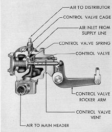
4C3. Air starting control valve. The air
starting control valve is bolted to the engine
frame near the control end on the side opposite
the control lever, and consists of a valve cage,
87
Figure 4-8. F-M engine air starting system.
88
valve, and valve spring. The valve is of the poppet type and has an integral stem. The valve is
held on its seat by the valve spring which is
placed between the valve head and the end
of the valve cage. The valve stem is grooved to
align with a drilled hole in the valve body, in
order to vent the valve of air when the valve is
closed. The end of the valve stern extends out
of the valve body, and the valve is opened
against valve spring pressure by a rocker arm.
When the rocker arm is withdrawn from the end
of the valve stem, the valve closes because of
spring pressure and air pressure acting on top
of the valve head.
Figure 4-9. Air starting control valve, F-M.
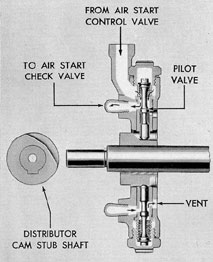
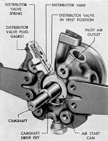
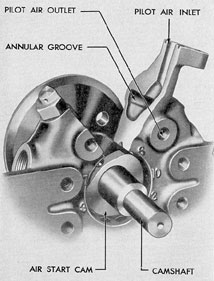
4C4. Air starting distributor. The air starting distributor body is a large circular casting,
cored to house the air starting distributor valves.
The distributor body mounts on the engine
frame at the control end of the upper crankshaft.
The distributor camshaft passes through the
center bore of the distributor body and is attached to and rotates with the upper crankshaft.
Figure 4-10. Cross section of air starting
distributor, F-M.
The distributor body houses one air starting pilot valve for each engine cylinder. These
valves are of the piston type with the inner end
of each valve stem acting as a cam follower.
During normal engine operation, the valves are
held out of contact with the camshaft by spring
pressure.
Each of the valve openings connects with
an air chamber extending around the outer circumference of the distributor body. During air
starting, this chamber is filled with air supplied
through the branch line when the air starting
control valve is opened. The air in this chamber
supplies pressure to each of the air starting pilot
valves. The spring tension in the valves is overcome by the air pressure, and each valve is
forced into contact with the cam on the camshaft. There is a low sector on the cam, and as
each valve approaches this sector of the cam,
the air pressure from the outer end moves the
pilot valve inward. This inward movement of
the valve stem opens a passage connecting the
pressure chamber in the distributor body with
89
Figure 4-11. F-M air starting distributor, pilot valve
in normal position out of contact with distributor cam.
Figure 4-14. Cutaway of air starting check
valve, F-M.
Figure 4-12. F-M air starting distributor,
pilot valve on low point of cam.
Figure 4-13. Cutaway of air starting
distributor, F-M.
90
an individual pilot air line to the operating piston in the air starting check valve at the cylinder. This action opens the check valve.
As the high sector of the cam approaches,
the valve is forced outward, shutting off the
actuating air to the check valve and venting the
pilot air line. Numbers marked on the distributor body at each branch line connection
indicate which cylinder each pilot valve serves.
Timing of the air starting distributor valves
is accomplished by positioning the distributor
camshaft. The camshaft is placed on the upper
crankshaft end and rotated until the proper geometrical angle of relation with the crankshaft is
made.
The camshaft is then keyed to the upper
crankshaft by means of a dowel pin. This timing
is done at the factory. Replacement camshafts
have two dowel pin holes for properly locating
the camshaft. The pin is placed in one hole for
right-hand rotation engines and in the other for
left-hand rotation engines.
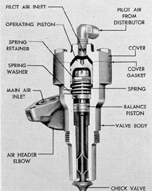
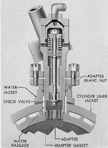
4C5. Air starting check valve. The air
starting check valves are enclosed in bronze
bodies and are located at the combustion chamber for each cylinder. Each check valve assembly fits into a water-cooled adapter.
The air starting check valve is held closed
principally by spring tension. Near the middle
of the valve stem is a balance piston which also
serves as a valve stem guide bearing. During
air starting there is a constant supply of air from
the air starting main header to the air chamber
between the valve head and the balance piston.
There is a slightly greater pressure area at the
balance piston than at the valve head. This prevents the starting air pressure from opening the
valve. An operating piston fits over the end of
the valve stem opposite the valve head.
When the individual distributor pilot valve
opens, actuating air is brought through an individual pilot air line to the air chamber above
the operating piston in the check valve body.
Pressure of the actuating air forces the operating
piston inward, overcomes the spring pressure,
and forces the check valve open. This action admits air directly from the starting air main
Figure 4-15. Cross section of installed air starting
check valve, F-M.
header into the combustion chamber of the
cylinder to move the pistons apart and turn the
crankshafts. As the individual distributor pilot
valve closes, pressure on the operating piston is
released, and spring action closes the check
valve. When the check valve is closed, the
pressure in the pilot lines is vented back through
the closed pilot valve and does not enter the
cylinder combustion chamber.
4C6. Maintenance. Frequent inspections
should be made of the air starting system to
see that line connections and valves are not leaking. Small leaks at the air start check valve will
permit gases of combustion to carbonize and
burn the valve seat. Unless this condition is
remedied by grinding and reseating the valve,
larger leaks with consequent serious damage to
the air starting system will result.