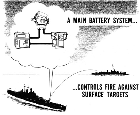
Main battery fire control systems in battleships and cruisers are designed primarily to solve the surface fire control problem which we have been discussing. The antiaircraft fire control problem involves certain factors which are not involved in the surface problem, and hence the two types of fire control systems vary somewhat in design but not in principle. In the next section we will discuss the antiaircraft fire control problem and the equipment used for its solution.
Although the present trend is toward development of automatic major-caliber guns and fire control equipment capable of handling either the surface or the air problem, the great majority of main battery systems now in use have very limited provisions for antiaircraft fire. The control of main batteries for fire against aircraft is made possible on most ships by cross-connections between the main battery and the dual purpose systems. However, because of their complexity these cross-connections will not be discussed in these sheets.
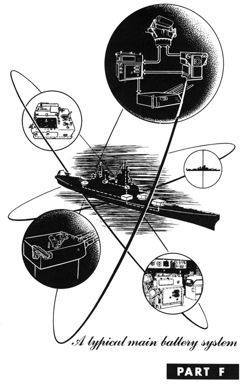
In this section you will learn more about a typical main battery fire control system-its components, their location, arrangement, and provisions for alternate and emergency methods of operation.
F-2
A TYPICAL MAIN BATTERY SYSTEM
The Components of a Typical Main Battery System (continued)
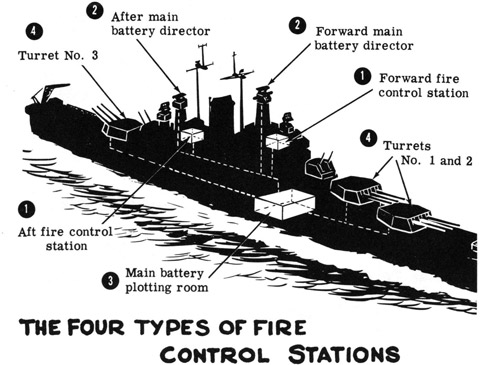
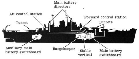
The principal components of a typical main battery fire control system, as you already know, are: (a) the director, (b) the rangekeeper, (c) the stable vertical, and (d) the turrets. These components are located in the following four types of stations aboard ship:
Each of these four types of station is in a position aboard ship where it can best serve its purpose. The control station is located above decks near the gun director and is used by the Gunnery Officer for observation and supervision; it may be equipped to take over many of the functions of the director and plotting room in an emergency.
The gun director is located high above decks so that it may sight and track the target by means of radar or optical equipment. The plotting room is situated well below decks for maximum protection against enemy fire, since it houses the intricate rangekeeper and stable vertical. The turrets which house the guns are located, of course, above deck and are heavily armored. Each of the four types of station will be discussed on the following sheets.
F-3
A TYPICAL MAIN BATTERY SYSTEM
The Fire Control Stations
Depending on the size and type of ship, there may be one or two control stations. If there are two, as shown in the illustration on the preceding sheet, one is located near the forward director and one near the aft director. Either or both of these stations may be equipped to take over many of the functions of the gun directors and plotting room in an emergency, or during auxiliary or secondary fire control which you will learn about later. On the other hand the control stations may serve merely as supervision and observation stations for the Gunnery Officer. In either case the stations contain equipment which allows observation of the gun fire, and indicating equipment which gives the range and bearing to target, target's and own ship's course and speed, etc.
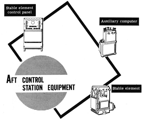
If the control station is intended to serve as a substitute in the event of casualty to the director or plotting room, or to control auxiliary or secondary fire, it will contain some or all of the following equipment:
1. An auxiliary computer
2. Radar equipment
3. A stable element
You will learn later on how this equipment functions in secondary and auxiliary fire control.
F-4
A TYPICAL MAIN BATTERY SYSTEM
The Fire Control Stations (continued)
Here and throughout the rest of this section of instruction sheets we will describe and refer to a fire control system which is typical of the main battery systems used aboard large Navy ships.
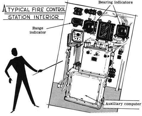
This typical system has two fire control stations, each of which contains: (1) an auxiliary computer, (2) periscopes, (3) bearing and range indicators, (4) a multiple turret-train indicator, and various switches and signal lights. In addition the aft control station contains a stable element and its control panel.
The auxiliary computer is an auxiliary instrument for use in secondary or auxiliary fire. It is smaller, simpler and less accurate than the range-keeper, but can perform its major functions. The periscopes are used to locate and track targets and to observe the gun fire. The bearing and range indicators receive and indicate target range and bearing from the directors. The multiple turret-train indicator shows whether or not the turrets are trained in accordance with gun train orders.
The stable element and its control panel measure level and crosslevel, and are used in secondary and auxiliary control.
F-5
A TYPICAL MAIN BATTERY SYSTEM
The Aloft Gun Directors
The typical main battery system we are considering uses two gun directors-one forward and one aft. The director is enclosed in a shield which supports the rangefinder and radar antenna.
Each director is equipped to measure target range, bearing and elevation either optically or by means of radar, and to transmit these values to the rangekeeper. In addition, the directors are equipped to take over some of the functions of the rangekeeper and stable vertical during auxiliary or secondary fire control. The directors also serve as lookout stations from which targets can be located and the fall of shot spotted.
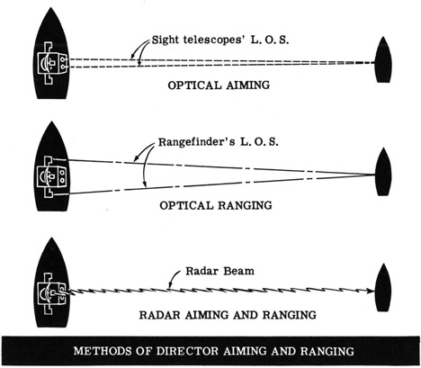
"Aiming" is the process of determining target bearing and elevation and may be performed by means of the sight telescopes or by radar. The former is called "optical aiming" and the latter "radar aiming."
"Ranging" is the process of establishing the distance to target from own ship and may be performed by means of the optical rangefinder ("optical ranging") or by radar ("radar ranging").
F-6
A TYPICAL MAIN BATTERY SYSTEM
The Aloft Gun Directors (continued)
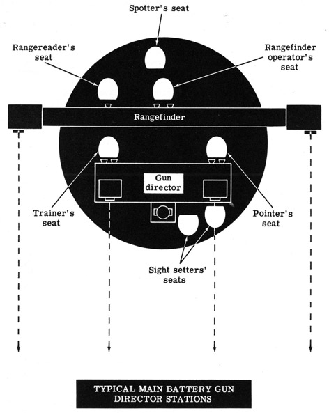
The director provides stations for a crew of seven men within the shield. At the rear of the director are stations for the trainer, pointer, spotter, rangereader and rangefinder operator. At the front of the director are stations for the two sight setters. Each of these stations will be discussed on the following sheets.
F-7
A TYPICAL MAIN BATTERY SYSTEM
The Aloft Gun Directors (continued)
When optical aiming is being employed the trainer sights through the trainer's sight telescope and tracks the target by turning his handwheels to bisect the target image with his telescope's vertical crosshair. Motion of his handwheels turns the entire director in train, and thus measures director train angle between the ship's centerline and the director's L. O. S. This angle is corrected for horizontal parallax by the horizontal parallax mechanism of the gun director, and is then continuously transmitted to the rangekeeper. During radar aiming the trainer uses a radar indicator for tracking the target and measuring director train.
The pointer sights through his sight telescope during optical aiming, turning his handwheels to keep the target bisected by the horizontal crossline of his instrument. He thus continuously measures director elevation, which is corrected for vertical parallax and transmitted to the range-keeper. For fire against surface targets, director elevation is small and we will not consider it in subsequent discussions.
The spotter occupies a position at the rear of the director, and through a hatch in the top of the director shield he is able to put his head and shoulders outside of the shield. From this position he uses binoculars to observe the fall of shot, and reports to the main battery plotting room on the accuracy of fire. Corrections are then made to gun settings to correct the errors. This procedure, as you know, is called "spotting. " The spotter also serves as a lookout for new, more susceptible targets.
The rangefinder operator observes the target through the rangefinder, keeping the target properly positioned so that the rangereader can read the range directly on the rangefinder scale. The rangereader telephones the value of range to the plotting room at fixed intervals (every few seconds), where it is then fed into the rangekeeper. This is called "intermittent optical ranging."
The two sight setter's units-one for sight angle and the other for sight deflection-are operated only in secondary or auxiliary fire control, at which time they receive on their indicators sight angle and sight deflection from the auxiliary computer or rangekeeper, and relay this information to the sight telescopes.
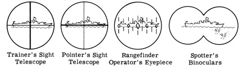
Shown below are the images seen by an observer using each of the optical instruments discussed.
F-8
A TYPICAL MAIN BATTERY SYSTEM
The Aloft Gun Directors (continued)
Two computing devices-the trunnion-tilt corrector and the director-elevation corrector-are located in the lower part of the gun director. These devices are employed only during secondary and auxiliary fire control for the computation of gun train and elevation orders when supplied with director train, level, crosslevel, sight angle and sight deflection. In primary fire control, the computing devices are locked in their zero positions.
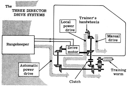
The director drive system is the combination electrical-mechanical mechanism used to position the director in train. The director can be trained by any one of three methods-automatic power, local power or manual.
When automatic power drive is being used, the director drive motor positions the director automatically in response to an electric signal from the rangekeeper. This signal is the computed change in bearing required to keep the director continuously on the target. If, during this type of control, the trainer's telescope crossline tends to drift off the target, he turns his handwheels to bring the director back on target, and thus signals the plotting room that a revision of estimated target quantities is needed in the rangekeeper setup.
In local power drive the trainer's handwheels directly control the electric drive motor. The rangekeeper, in this case, has no control over the positioning of the director.
In manual drive the trainer's handwheels are connected through a clutch to the training worm, and the director and shield are rotated solely by the power applied by the trainer to his handwheels.
F-9
A TYPICAL MAIN BATTERY SYSTEM
The Plotting Room
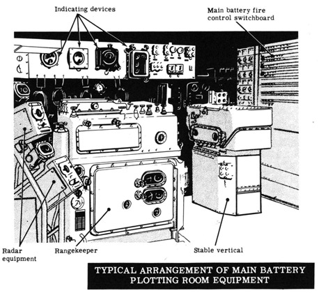
The main battery plotting room is located within the ship's hull, below the waterline and beneath the armored deck. This location ensures maximum protection against damage due to enemy action.
Battleships usually have two main battery plotting rooms-one forward and one aft. Either of these plotting rooms can control any part or all of the main battery, and, in an emergency, cross-connections enable them to control secondary battery fire. Cruisers may have only one main battery plotting room which controls the fire of all main battery guns.
The arrangement and location of the equipment in main battery plotting rooms differ somewhat among the various types and sizes of ships. However, all main battery plotting rooms contain basically the same equipment, regardless of its location or arrangement. The principal items of equipment in the plotting room of the typical main battery system we have been considering are:
The plotting room is the primary source of gun train and elevation orders. To it, in primary fire control, come the data measured and estimated at the directors; from it go the gun orders used to aim the guns.
F-10
A TYPICAL MAIN BATTERY SYSTEM
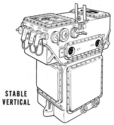
The Plotting Room-Stable Vertical
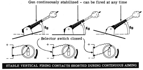
You already know of the function of the stable vertical in maintaining the true vertical and thus continuously measuring level and crosslevel, which are transmitted to the rangekeeper. This is the primary job of the stable vertical and has already been discussed. Another of its functions is that of a remote firing station. Its use as such depends on the method of aiming being employed-"continuous aiming" or "selected level aiming."
"Continuous aiming" is always used under normal sea conditions. Under this system of aiming, the gun train order and the gun elevation order are continuously corrected for inclination of the deck. Thus the guns always maintain their position in space and may be fired at any time, regardless of the roll and pitch of the ship. This method of operation is limited to use when the sea is relatively calm, requiring only minor corrections to gun orders to compensate for deck tilt.
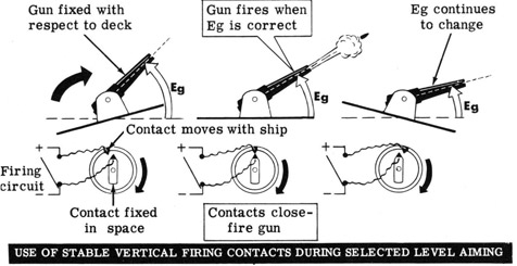
"Selected level aiming" is used when sea conditions make it difficult to keep the guns on target. The guns are not continuously stabilized, but move with the ship and can only be fired at the moment the aim is correct.
F-11
A TYPICAL MAIN BATTERY SYSTEM
The Plotting Room-Stable Vertical (continued)
The stable vertical is provided with a pair of firing contacts wired in series with the firing circuit, and in parallel with a switch which can short the contacts. One of the contacts is fixed in space by the stable vertical's gyro, while the other moves with the ship. The contacts can be adjusted to close and thus fire the guns automatically when the rest of the firing circuit is complete at any desired position of the ship's deck. These contacts are used during selected level aiming to automatically fire the guns at the instant at which they are in the correct position.
During continuous aiming, the guns, kept always stabilized on the target by continuously changing gun orders, can be fired at any time. This is accomplished by closing the selector switch and thus shorting the automatic firing contacts. The guns are then fired by an operator at the stable vertical or at some other station. In continuous aiming the stable vertical does not function as an automatic firing station.
F-12
A TYPICAL MAIN BATTERY SYSTEM
The Plotting Room-Rangekeeper
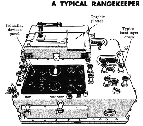
The rangekeeper includes most of the controlling, computing, and transmitting fire control mechanisms for the main battery. The instrument is a combined rangekeeper, bearing keeper, predictor, deck-tilt corrector, trunnion-tilt corrector and graphic plotter. Supplied with the proper hand and automatic inputs, the rangekeeper will compute, indicate and transmit automatically to the turrets and directors the information necessary to point the guns and to train the directors continuously on the target. Gun orders, which are the outputs of the rangekeeper, include the necessary corrections for drift, wind, variation in initial velocity, relative motion of ship and target, level and crosslevel. The rangekeeper is equipped with synchro transmitters and receivers which are used to transmit and receive electrical inputs and outputs.
The illustration below is a top view of a typical rangekeeper showing the hand input cranks, the graphic plotter, and the various indicating devices incorporated in the rangekeeper.
On the next sheet we will see how the various inputs are normally introduced, and their sources.
F-13
A TYPICAL MAIN BATTERY SYSTEM
The Plotting Room-Rangekeeper (continued)
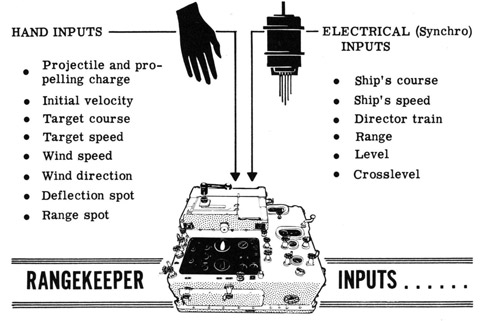
By this time you should know what information the rangekeeper requires for the solution of the fire control problem and the subsequent computation of gun orders. The table and illustration below show how the various inputs are normally introduced to the rangekeeper, and their source.
INPUT TO RANGEKEEPER
INTRODUCED BY
SOURCE
1. Projectile and powder charge being used
Hand
Gunnery officer
2. Initial velocity
Hand
Interior ballistics corrections
3. Target course
Hand
Gun director estimate
4. Target speed
Hand
Gun director estimate
5. Wind direction
Hand
Ship's meteorologist
6. Wind speed
Hand
Ship's meteorologist
7. Deflection correction for fall of shot
Hand
Spotter
8. Range correction for fall of shot
Hand
Spotter
9. Ship's course
Synchro transmission
Ship's gyro compass
10. Ship's speed
Synchro transmission
Pitometer log
11. Director train
Synchro transmission
Gun director
12. Range
Synchro transmission
Gun director
13. Level
Synchro transmission
Stable vertical
14. Crosslevel
Synchro transmission
Stable vertical
F-14
A TYPICAL MAIN BATTERY SYSTEM
The Plotting Room-Rangekeeper (continued)
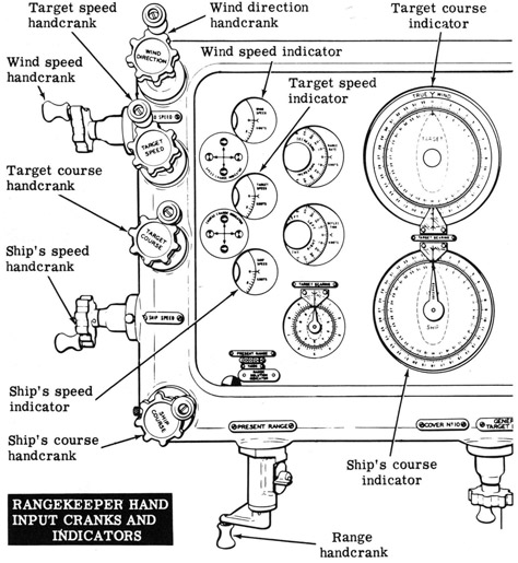
The indicating devices on the top of the rangekeeper give the rangekeeper operator at a glance the value of the hand inputs. They allow him to adjust these inputs, in accordance with the information received by telephone from the source of the input, by turning the handcrank until the proper value is shown on the indicator. A portion of the face of the rangekeeper is illustrated below, showing the principal hand input cranks and their associated indicators.
The graphic plotter, mentioned and illustrated on a previous sheet, automatically plots target position and records the rounds fired. It thus provides a permanent record of the combat action which is invaluable for post-firing analysis. The graphic plotter is no longer used to solve the fire control problem during combat.
F-15
A TYPICAL MAIN BATTERY SYSTEM
The Plotting Room-Radar Equipment
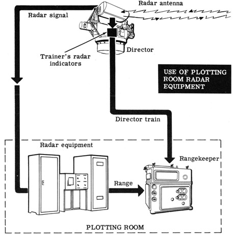
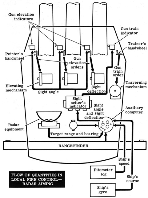
Units of the radar equipment used with the antenna mounted on top of the director are located in the plotting room. When radar ranging and aiming is being used, range measurement is controlled by the radar-range operator in the plotting room, who operates the radar-range unit. From this unit, range is transmitted to the rangekeeper.
The director trainer has a radar indicator at his station in the director which enables him to measure director train during radar aiming. This information is then transmitted to the rangekeeper in the same manner as during optical aiming.
As you know, the fire control radar is used at night and whenever visibility conditions are poor. In addition, however, radar ranging is often used when optical ranging could be employed, due to its greater accuracy and the fact that it allows continuous range measurement. You will learn more about the use of radar in fire control in a later section.
F-16
A TYPICAL MAIN BATTERY SYSTEM
Other Plotting Room Equipment
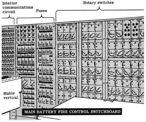
The main battery fire control switchboard, located in the plotting room, consists of rotary switches, a fuse panel, and a snap-switch panel for the interior communications circuits. The switchboard serves as a central point from which signals can be switched to and from the various elements of the fire control system as required for operation in different methods of fire control. In other words, the switchboard selects the proper route for the transmission of quantities within the system during primary, secondary, or auxiliary fire control.
The plotting room also contains a "multiple turret train indicator," similar to that in the control stations, which shows whether or not the turrets are trained in accordance with gun orders. A "bearing indicator" shows target bearing and own ship's course. A "director train indicator" shows the train angles of the directors. The dead-reckoning tracer is a device which plots own ship's course and is used during shore bombardment operations.
Numerous signal lights, dials, buzzers, telephones and other equipment provide means for interior communication between the plotting room and the other fire control stations.
F-17
A TYPICAL MAIN BATTERY SYSTEM
The Turrets
Fire control equipment installed in the gun turrets includes devices which elevate and train the guns automatically in response to gun orders from the rangekeeper, as well as equipment which enables the guns to be operated independently of the rangekeeper and director-in local fire control.
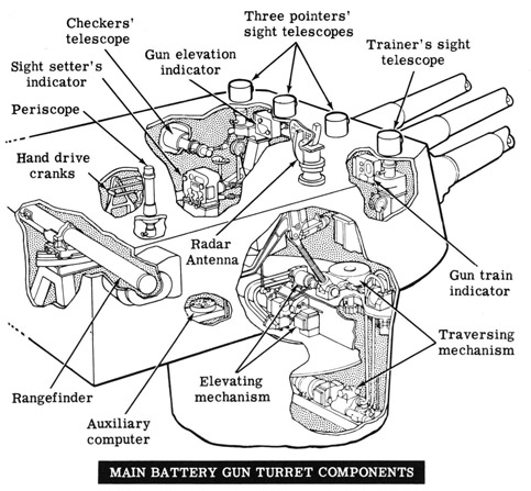
The principal fire control equipment in a typical main battery gun turret is shown in the illustration below. The elevating and traversing mechanisms serve as the links between fire control and gunnery by positioning the guns in elevation and train in accordance with the gun orders.
Under normal combat conditions, when the aiming of the turret's guns is being controlled by the gun director, gun orders are transmitted directly from the rangekeeper to the elevating and traversing mechanisms in the turrets and the guns are automatically positioned. In this method of operation, some units of the turret fire control equipment are inoperative and others serve to check the director's aiming and ranging. On the following sheet we will discuss the various pieces of fire control equipment within the turrets and see what their functions are.
F-18
A TYPICAL MAIN BATTERY SYSTEM
The Turrets (continued)
Each turret is commanded by a turret officer who occupies a booth at the rear of the turret. The booth is equipped with a periscope which enables the turret officer to observe the target, estimate its course and speed, and spot the fall of shot.
An auxiliary computer in the turret officer's booth is used instead of the rangekeeper to solve the fire control problem in local fire control. Like the computer located in the control stations, it is smaller, simpler and less accurate than the rangekeeper, and is intended only for emergency use.
Many gun turrets contain their own radar equipment, the antenna being mounted on the top of the turret. This equipment is used to check director-determined range and bearing in primary and secondary control, and is used instead of the optical equipment in local control. The optical equipment listed below is used only as standby in case of failure of the radar system.
The rangefinder, mounted at the rear of the turret officer's booth, provides a means for checking the range determined by the gun director in primary and auxiliary fire control. It is used in local fire control to supply range to the turret's auxiliary computer.
The trainer's and pointer's sight telescopes are located at the front of the turret. There are three pointer's telescopes-one for each gun-since the guns are controlled independently in elevation. Only one trainer's sight telescope is required, however, because all guns move together in train. The pointers' and trainer's sights are used to aim the guns in local control and to check the gun director's aim in other methods of control. The checker's telescope, on the extreme left side of the turret, is used to check the accuracy of the sight telescope settings.
When the guns are not positioned by direct gun orders from rangekeeper to the elevating and traversing mechanisms, automatically the gun orders are transmitted via the sight setter's indicator to the gun elevation and train indicators. These instruments show the required gun settings on one dial and the actual position of the gun on another dial. The trainer and pointers then turn their handwheels which actuate the elevating and traversing mechanisms until the readings on the two dials coincide. Hand drive cranks are provided so that the guns can be positioned manually in the event of a power failure.
In addition to the equipment already mentioned, the turret officer's booth contains a multiple turret train indicator and various switches and signal lights.
F-19
A TYPICAL MAIN BATTERY SYSTEM
The Turrets (continued)
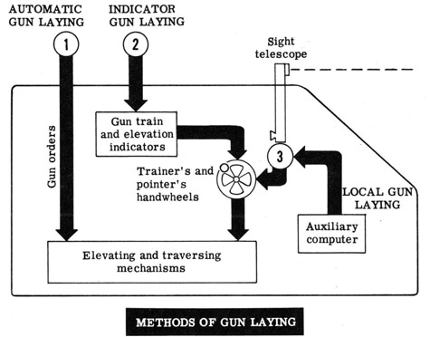
The turret equipment makes possible several methods of "laying" the guns in elevation and train. These methods are: (1) automatic gun laying, (2) indicator gun laying, and (3) local gun laying. The first two methods may be used in either primary, secondary or auxiliary fire control, while the third method is used only during local control.
In automatic gun laying, the gun orders are transmitted from the range-keeper or control station auxiliary computer to the elevating and traversing mechanisms. During indicator gun laying, the gun orders position the gun train and elevation indicators, and the trainer's and pointers' hand-wheels are turned to lay the guns and match indicator dials, as explained on the preceding sheet.
You will recall that sight angle and sight deflection are the angles through which a gun must be elevated and trained away from the line of sight to correct for drift, wind, range, etc. These angles are introduced into the sight telescopes in local gun laying. The handwheels are then turned to lay the guns and bring the sights on target.
Now let's go on to learn about the various methods of fire control system operation.
F-20
A TYPICAL MAIN BATTERY SYSTEM
The Different Methods of Fire Control
As you already know, the main battery fire control system may be operated in several different ways. This flexibility permits fire to be maintained in the event of casualty to one or more elements in the system and allows the guns to be fired at two or more targets at the same time.
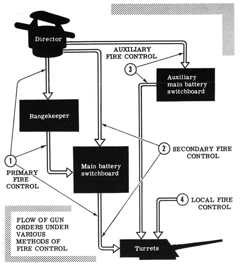
The different methods of fire control differ in the way the gun orders are computed and transmitted to the gun elevating and traversing mechanisms. The four methods are: (1) primary control, (2) secondary control, (3) auxiliary control and (4) local control. These methods are shown in the illustration below, with the arrows representing the flow of information. A brief description of each method is given on the next sheet, with more detailed discussion of each on the following sheets.
F-21
A TYPICAL MAIN BATTERY SYSTEM
The Different Methods of Fire Control (continued)
In primary fire control the target is tracked by the director; gun orders are computed by the rangekeeper and transmitted to the turrets via the main battery switchboard through which all system components are connected. In secondary fire control the target is tracked by the director and the gun orders computed by auxiliary equipment in the fire control stations; gun orders are then transmitted to turrets via the main battery switchboard. Auxiliary fire control is similar to secondary control, except that all system components are connected through the auxiliary main battery switchboard located in the ship's after gyro room. In local fire control each turret uses its own instruments and sights to solve the problem and aim the guns and operates as an independent unit.
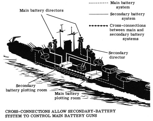
In addition to these four methods of main battery control, cross-connections are provided between the main battery system and the secondary battery system which allow the guns of the main battery to be controlled by the secondary battery directors. Because of differences between the two systems, corrections must be applied to the main battery gun orders when they are computed by the secondary battery system. Due to the complexity of the cross-connections between the two systems and the limited use of the method, it will not be discussed here.
F-22
A TYPICAL MAIN BATTERY SYSTEM
Primary Fire Control
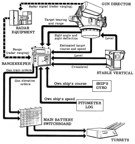
Primary fire control is the method ordinarily employed in combat. It is the most accurate and efficient way of controlling a ship's main battery fire power, and is always used unless one of the elements of the fire control system is damaged by enemy action. In our previous discussions on the function of the various elements of the main battery system in the solution of the fire control problem, we have been considering normal operation-primary fire control. The illustration below will help you recall the part each component plays in main battery primary fire control.
FLOW OF QUANTITIES IN PRIMARY FIRE CONTROL
F-23
A TYPICAL MAIN BATTERY SYSTEM
Secondary and Auxiliary Fire Control
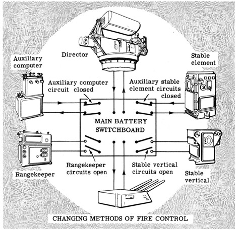
Because it is desirable to employ primary fire control whenever possible, maximum protection is given to the plotting room in order to prevent damage to the rangekeeper and stable vertical. But provision must be made for alternate means of operation if these instruments are damaged. By means of switches on the main battery switchboard, the method of operation can be changed quickly from primary to secondary or auxiliary control. This is done by removing the rangekeeper and stable vertical from the fire control system circuits, and connecting the auxiliary computer and auxiliary stable element (both located in the fire control station) to the system.
In effect the rangekeeper has been replaced by the auxiliary computer, and the stable vertical has been replaced by the auxiliary stable element. The flow of information, however, is changed somewhat in secondary and auxiliary fire control, to compensate for the limitations of the auxiliary equipment. Gun orders no longer originate in the computer but are now determined at the director itself, using information supplied by the auxiliary equipment.
F-24
A TYPICAL MAIN BATTERY SYSTEM
Secondary and Auxiliary Fire Control (continued)
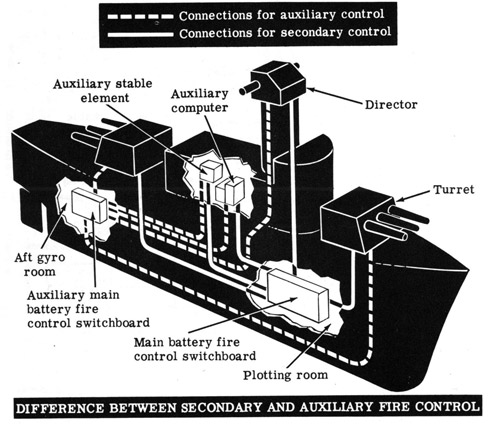
Before we get into the details of how the equipment functions in secondary and auxiliary control, let's get straightened out about the difference between these two methods of control. The difference is slight but important. The equipment used and the flow of information are exactly alike in both methods. The only difference lies in the fact that in secondary control all electrical connections between the various elements are made through the main battery switchboard located in the plotting room, whereas in auxiliary control these connections are made through the auxiliary main battery switchboard located in the ship's aft gyro room.
A moment's thought will convince you that if enemy action causes damage to the rangekeeper and stable vertical, the same action may put the main battery fire control switchboard out of action. If this happens, secondary control cannot be employed since it depends on the main switchboard. So again by opening and closing the proper switches, the auxiliary switchboard can be made to serve in place of the main switchboard, as shown above.
Now let's go on and see how the equipment functions in secondary and auxiliary fire control.
F-25
A TYPICAL MAIN BATTERY SYSTEM
Secondary and Auxiliary Fire Control (continued)
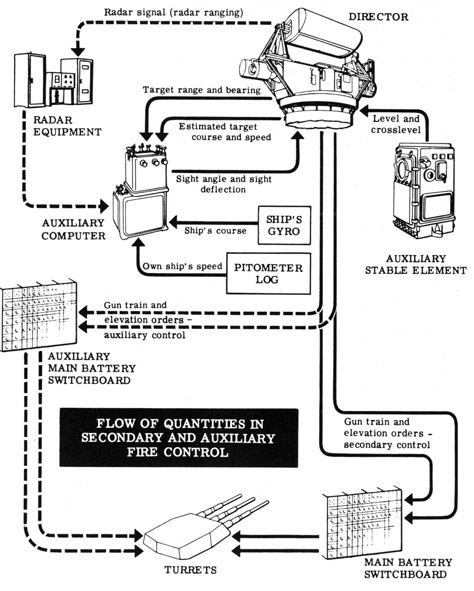
The illustration below shows the transmission of quantities between the fire control system components in secondary and auxiliary fire control. You will note that the only difference between the two methods, as explained on the preceding sheet, is the use of the auxiliary main battery switchboard in auxiliary control.
On the next sheet we will discuss the flow of quantities and compare secondary and auxiliary to primary control.
F-26
A TYPICAL MAIN BATTERY SYSTEM
Secondary and Auxiliary Fire Control (continued)
Don't let the diagram on the preceding sheet frighten you-it's not as bad as it seems. Let's start at the director and follow the transmission Of quantities, at the same time comparing secondary and auxiliary control to primary control.
Just as in primary control, the director measures target range and bearing and estimates target course and speed. These quantities are transmitted to the auxiliary computer in the fire control station. If radar ranging is being employed, range is transmitted via the radar equipment in the plotting room or the control station. The auxiliary computer also receives own ship's course and speed from the ship's gyro and pitometer log, just as the rangekeeper does in primary control. However, the computer does not receive level and crosslevel from the stable element. Thus, instead of calculating gun orders, as does the rangekeeper, the computer determines sight angle and sight deflection (which do not correct for deck tilt) and transmits these quantities to the director. The director then combines sight angle and sight deflection with level and crosslevel received from the auxiliary stable element and transmits gun train and elevation orders to the turrets (via the main battery switchboard in secondary control and via the auxiliary main battery switchboard in auxiliary control).
You can see from the above discussion, and from a comparison of the flow of quantities in primary and secondary control, that the major difference between primary and secondary (or auxiliary) control is that in primary control gun orders are computed in the rangekeeper, whereas in secondary control they are determined at the director.
Do you see now how flexible the main battery fire control system is? In primary control any director can control all or any part of the main battery. If secondary control becomes necessary this is still true, as it is in auxiliary control. The auxiliary equipment and switchboards certainly make the system very flexible. But, you may ask, what happens if all directors are put out of action, or the auxiliary computer and stable element are damaged, or communications severed to a single turret? Local fire control then becomes necessary. Let's go on to see what happens under this method.
F-27
A TYPICAL MAIN BATTERY SYSTEM
Local Fire Control
The fire control methods we have so far discussed-primary, secondary and auxiliary-depend on the use of a gun director and computing equipment located in the plotting room or control stations. If enemy action cuts communications to and thus isolates a turret from the rest of the system, the guns of that turret must be controlled by equipment located within the turret itself. For this reason, as you know, each turret is equipped to solve the fire control problem locally if necessary.
Local control is the least accurate of the four fire control methods, due to the limitations of the turret fire control equipment. The turrets contain no stable element, so no correction can be made for level or crosslevel. In addition the auxiliary computer used in local control is less accurate than either the rangekeeper or the control station's auxiliary computer.
Local fire control can be used to control a single turret while the rest of the battery is under primary, secondary or auxiliary control; it can also be employed by all turrets to control the whole battery in the event that damage to the system makes it impossible to use primary, secondary or auxiliary control.
F-28
A TYPICAL MAIN BATTERY SYSTEM
Local Fire Control (continued)
The fire control equipment installed in the turrets has already been discussed. The basic components and the transmission of data between components when the radar equipment is in use are shown in the illustration below. The flow of quantities when the optical instruments are in use is shown on the next sheet.
F-29
A TYPICAL MAIN BATTERY SYSTEM
Local Fire Control (continued)
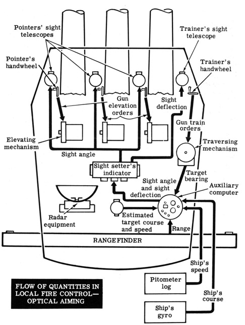
The flow of quantities in local fire control during optical aiming is shown below. On the next sheet we will discuss the illustrations on both this and the preceding sheet.
F-30
A TYPICAL MAIN BATTERY SYSTEM
Local Fire Control (continued)
In local fire control the auxiliary computer located in the turret officer's booth is used to solve the fire control problem. It receives the same basic inputs as the rangekeeper or control station auxiliary computer, except that it doesn't receive or correct for level and crosslevel.
When the radar equipment is in operation, the radar operator tracks the target, and target range and bearing are automatically transmitted from the radar equipment to the auxiliary computer. The auxiliary computer also receives ship's course and speed, and computes sight angle and sight deflection. These quantities are transmitted, via the sight setter's indicator, to the elevation and train indicators. The trainer and pointers turn their handwheels to keep the dials aligned on the gun elevation and train indicators, thus positioning the guns.
When the radar equipment is not being used, the optical instruments determine range and bearing. As the trainer turns his handwheels to keep the vertical crossline of his telescope trained on the target, the traversing mechanism positions the turret in train. This establishes target bearing which is transmitted to the computer. The rangefinder measures range and transmits it to the computer, which also receives own ship's course from ship's gyro and own ship's speed from the pitometer log. The turret officer observes the target through the periscope, estimates its course and speed, and sends this information also to the computer.
The auxiliary computer solves the fire control problem and sends sight angle and sight deflection to the sight setter's indicator. Sight angle is dispatched from there to each of the three pointer's sight telescopes. As this angle is introduced it moves the telescopes so that it is necessary for the pointers to turn their handwheels to keep their sights on the target. In so doing they position the guns in elevation, elevating them through the sight angle. The sight setter's indicator also transmits sight deflection to the trainer's sight telescope. Again, to keep his sight on target, the trainer must move his handwheel, thus positioning the turret and hence the guns in train.
F-31
A TYPICAL MAIN BATTERY SYSTEM
Summary of Fire Control Methods
Let's take another look at the four methods of fire control, and review the part played by each of the system components in each type of control. The illustration below indicates the connections between elements in primary fire control.
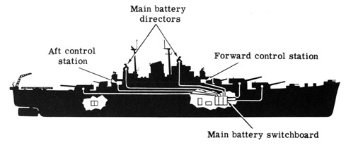
PRIMARY FIRE CONTROL
In primary fire control the rangekeeper, stable vertical, gun directors and turrets are connected through the main battery switchboard in the plotting room. This method of control is always used under normal combat conditions.
SECONDARY FIRE CONTROL
In secondary fire control, used in the event of damage to the rangekeeper or stable vertical, the rangekeeper and stable vertical are removed from the system, and the auxiliary computer and auxiliary stable element in the fire control stations take their place. All elements of the system are connected through the main battery switchboard in the plotting room.
F-32
A TYPICAL MAIN BATTERY SYSTEM
Summary of Fire Control Methods (continued)
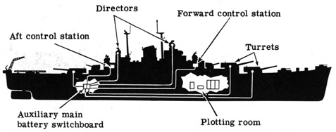
Auxiliary control is identical to secondary control except that the system elements are connected through the auxiliary main battery switchboard located in the ship's aft gyro room. This method is used only if damage to the main battery switchboard makes secondary control impossible.
AUXILIARY FIRE CONTROL
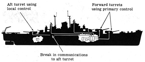
The fourth method of control is local fire control, in which each turret operates independently of the rest of the fire control system. This method is used only when disruption of communications or damage to other system components makes it impossible to use any of the three other methods to control a turret's guns. In the illustration below, communications to the aft turret have been cut off; it is using local control, while the forward turrets are under primary control.
LOCAL CONTROL OF AFT TURRET
F-33
A TYPICAL MAIN BATTERY SYSTEM
Review of Main Battery Fire Control
In this section of instruction sheets you have seen what fire control equipment makes up a typical main battery fire control system, and how this equipment is used in various methods of control. You should have a pretty complete understanding of the function of each system component in the solution of the fire control problem, and you should be familiar with each of the four methods of control and the conditions under which each is used.
Before leaving the study of a main battery system and going on to learn about antiaircraft fire control, let's review the basic equipment used in each of the four control methods, and its location.
Type of
Control
Equipment
Used
Location of
Equipment
Primary
1. Gun director
2. Rangekeeper
3. Stable vertical
4. Radar equipment
5. Main battery switchboard
Now let's go on to see how the general principles of fire control are applied to solve the antiaircraft fire control problem. You will find many similarities and some differences between the surface and the antiaircraft problems, and between the equipment used to solve the problems. But if you thoroughly understand what you've studied so far you'll have no trouble.