Note: The prefix letter on all cables except the
"M" cable indicates the number of conductors
in the cable.
The suffix numeral on all cables except the
"M" cable indicates the size of the conductors
in 1,000 C.M. (circular mils).
The prefix letter "M" on cables indicates a
multiple conductor cable (two or more conductors) and the suffix numeral represents the
number of conductors.
The size of the wire in all "M" conductor
cables is No. 16.
i. Learn to distinguish the circuits by the circuit markings
on the blueprint.
109
B. Procedure (continued)
1) Lighting and power
F
General lighting and power
FB
Battle lighting and power
XFE
Emergency lighting and power
When no numeral precedes the circuit marking, the
circuit is a feeder
FB 100
When a numeral precedes the circuit marking, and no
letter or number follows the marking, the circuit is
a main.
1 - FB - 100
The numeral "1" indicates the first position on
Power Panel, K. Box, etc., "2" the second position,
etc.
When a numeral precedes the circuit marking and a
letter follows, the circuit is a submain.
1 - FB - 100 A
The "A" indicates the first position, "B" the
second position, etc.
A numeral preceding the circuit marking and a
letter and a numeral following it indicate a branch
or a sub-branch.
1 - FB - 100 A 1
The last numeral "1" indicates the first position,
"2" the second position, etc.
When the number following the circuit marking is
one hundred series (FB 100), the circuit can be
assumed to be a lighting circuit of 120 volts; the
figure "1" indicating the voltage. The remaining
figures in the number will be the circuit number.
There will be exceptions to this rule; for instance,
a circuit with the number "165" or "326," and a few
others. These will be located on the power print,
for they are considered power circuits. Generally
the figures "1" and "4" indicate a lighting voltage
of 120, or a power voltage of 440, respectively.
2) Interior communication is called I.C.
3) Fire control is called F.C. circuits (guns)
4) Sound circuits
110
B. Procedure (continued)
5) Radio
6) Degaussing
j. Keep all large cables within the machinery spaces
inboard of the cable rack. The remainder are to be
installed in the way they will best fit the particular
location.
k. Whenever possible, group power and light, I.C. and
fire control, and radio.
2. CHECK ALL DETAILS ON MAIN WIREWAY PRINT SUCH AS CABLE
MARKINGS AND THEIR INTERPRETATIONS, POWER, LIGHTING, FIRE
CONTROL, I.C., AND RADIO.
a. Identify the different circuits, noting service they
perform and where they will be found aboard a ship.
b. List in small notebook all I.C. and fire control
circuits, cable data and stuffing tube hole data and
any other information that may be helpful.
c. Study prints of various types of hangers, in order to
visualize types of hangers used in different cable runs.
3. OBTAIN BLUEPRINTS COVERING ALL THE CIRCUITS AND LIST EACH
CIRCUIT INDIVIDUALLY.
a. Start with the lighting circuit.
b. Locate the bulkheads in the section selected.
c. Begin with the forward bulkhead of the section and
consider this as the source of the cables that enter
the section.
Note: The source of the remaining cables will be at
the point where above cables start. The place
or point where the cables stop or leave the
section will be the cable destination.
d. When listing the cables, show the number of the frame
or bulkhead of the cable source and destination.
1) If the destination of the cables is a box, show the
kind of box and its location.
2) If the destination is a tube area, show direction,
whether up or down, and location of the area, frame
number, port or starboard or C/L, whichever the case
may be.
e. Omit the local runs when laying out main runs. They
are to be put in later.
111
B. Procedure (continued)
f. List the cables in the following manner:
Cable
Kind
Circuit
Source
Destination
THFA3
Light
1-FB-10 2
BLK #159
BLK #183
THFA3
Light
FB-10 2
BLK #159
Fr. 170-2K box C/L
THFA3
Power
F-426
BLK #159
BLK #183
THFA3
Power
F-326
BLK #159
BLK #183
THFA3
Power
F-434
BLK #159
Fr. 170-up C/L
MHFA10
I.C.
LD#C-LC25
BLK #159
Fr. 166-20 wire box
MHFA4
F.C.
LD#G-GU5
BLK #159
Fr. 170-up C/L
MHFA19
Radio
LD#R-RRB
BLK #159
Fr. 180-Term. outlet
4. RE-ARRANGE THE ABOVE LISTING TO SUIT THE BRANCHING OFF OF
THE CABLES.
a. Arrange the cables so that the through cables will
extend to the outboard of the run. The next longest
group of cables will follow the through cables.
b. Place each cable in its proper place with respect to
the farthest aft.
Cables Listed to Suit Branching off of the Cables
Cable
Kind
Circuit
Source
Destination
THFA3
Light
1-FB-102 BLK
159 BLK 183
THFA3
Light
FB-102
BLK 159
Fr. 170-2K box C/L
THFA3
Power
F-426
BLK 159
BLK 183
THFA3
Power
F-326
BLK 159
BLK 183
THFA3
Power
F-434
BLK 159
Fr. 170-up C/L
MHFA10
I.C.
LD C-LC25
BLK 159
Fr. 166-20 wire box
MHFA4
F.C.
LD G-GU5
BLK 159
Fr. 170-up C/L
MHFA19
Radio
LD R-RRB
BLK 159
Fr. 180-Term. outlet
5. MAKE A COMPOSITE LIST OF THE CABLES IN TEE ABOVE ORDER.
a. Place the through cables, light, power, I.C., fire
control, and radio to the outboard of the run, and
place the remainder of the cables according to their
branching-off point.
112
B. Procedure (continued)
Composite Listing
Cable
Kind
Circuit
Source
Destination
THFA3
Light
1-FB-102
BLK 159
BLK 183
THFA3
Power
F-426
BLK 159
BLK 183
THFA3
Power
F-326
BLK 159
BLK 183
MHFA10
Radio
LD R-RRB
BLK 159
Fr. 180-Term. outlet
THFA3
Power
F-434
BLK 159
Fr. 170-up C/L
THFA3
Light
FB-102
BLK 159
Fr. 170-2K box C/L
MHFA4
F.C.
LD G-GU5
BLK 159
Fr. 170-up C/L
MHFA10
I.C.
LD C-LC25
BLK 159
Fr. 166-20 wire box
6. MAKE A COMPOSITE DRAWING OF THE ABOVE LISTING.
a. Obtain the following supplies:
Drawing board
T-square
Pencils
Paper
Triangle
Thumb tacks
Eraser
b. Make a drawing from the composite listing, showing
bulkheads, boxes, tube areas, etc.
Note: Make sure to properly name each cable.
7. MAKE A DRAWING OF THE CABLRS IN RACK AT BULKHEADS.
a. Check main wireway to determine the type of hangers
to use.
b. Look up the type on blueprint.
c. Study this type carefully, noting all details.
d. Make a sketch of this type of hanger and show cables
in their proper location.
8. LAY OUT TUBE AREAS.
a. Secure shipfitters print covering the bulkhead to be
considered.
b. Check carefully for size of area.
c. Check to see if the tubes are put directly into the
bulkhead, or if a plate is cut out.
d. Check the kind of plate (lap of insert).
e. Check the kind of tubes to be used.
f. Refer to tube and hole chart to obtain proper sizes.
113
B. Procedure (continued)
g. Lay out an area on paper the proper size.
h. Arrange tubes to fit into the area, keeping as near as
possible the same location as that in which the cables
lay in the rack.
i. Have no crosses at the area.
j. Do not allow cables to cross one another from one side to
the other. However, cables may change tiers by either
dropping down or going up.
k. When the area has been properly arranged to suit the
cables, make a permanent layout of the area on heavy
cardboard by drawing circles the actual size and spacing
of the tubes and printing the cable and tube designation
within each circle.
l. In laying out cables in the machinery spaces, keep all
large cables to the inboard of the rack, and all through
cables on the bottom tiers.
m. In the rest of the ship, keep through cables to outboard
of rack and on bottom of tiers.
n. Where possible, arrange cable grouping as shown below:
Power
Light
) ) Together )
I.C.
F.C.
) ) Together )
Radio
) Alone
o. Maintain polarity of single-conductor cables in order to
avoid magnetic loops for all D.C. circuits. Negative
and positive leads should never exceed 12-inch spacing;
that is, D.C. circuits should be neutralized at all times.
p. Use multi-conductor cable when practicable; that is,
duplex for single phase and triplex for 3 phase.
Note: When for special reasons it is necessary to run
separate phase leads, the individual leads for the
single or 3-phase circuits should be kept as
close together as possible throughout their lengths.
They should be twisted together not greater than
16 times the pitch diameter. Single-conductor cables
carrying A.X. should not be grouped in the same
hangers with cables carrying D.C.
114
II. CABLE TYPES AND USES
TYPE SLPP AND SLPA--These letters refer to single lighting and power
plain, and single lighting and power armored. This cable ranges
from 4,000 to 1,500,000 circular mils in approximate cross-sectional area. The smallest size, approximately 4,000 circular
mils, consists of the single-stranded conductor, a layer of
40 per cent rubber, a layer of rubber-filled tape, and a cotton
braid. Type SLPA has, in addition, an outside layer of basketweave armoring.
All cable of these two types with the exception of the smallest
size is made differently. These cables consist of the stranded
conductor, varnished cambric insulation, rubber-filled tape,
reinforced rubber sheath, rubber-filled tape, and a cotton
braid. The armored variety of these larger sizes has a basketweave metal armoring in place of the cotton braid.
Plain cable is to be used in turret columns and like installations where flexibility is important. The armored type, SLPA,
is used in permanentlyinstalled lighting and power leads
throughout the vessel where a single conductor is required.
TYPE SRLL--This is a single-conductor, low-tension, lead-sheathed
cable for radio use only.
TYPE SRHLA--This is a single-conductor, low-tension, lead-sheathed
cable for radio use only.
TYPE DLPP AND DLPA--This is a duplex cable for lighting and power
use, and may be obtained either plain or armored. As in the
case of the single conductor of this type, the smallest size is
manufactured differently from the larger sizes, The smallest
size, approximately 4,000 circular mils, consists of two
conductors, each one of which has a layer of 40 per cent rubber
insulation and a layer of rubber-filled tape. The largest size
is 400,000 circular mils. (SLPA insulation is in the same
sizes, from 4,000 circular mils to 1,600,000 circular mils.)
These two conductors are twisted together. Dry jute filler is
used to obtain circularity of cross section. The conductors
are then covered with a layer of rubber-filled tape, a layer
of 40 per cent rubber, another layer of rubber-filled tape,
and a cotton braid. In the case of the armored variety, a
basket-weave metal armoring is used instead of the cotton braid.
The larger sizes run from 9,000 to 60,000 circular mils
approximate cross-sectional area. In these sizes, each conductor
is covered with varnished cambric. The two conductors are then
twisted together and filled with jute, as in the smallest
size described above. The conductors are then covered with a
double layer of varnished cambric tape half lapped, a layer
of rubber-filled tape, and a cotton braid. In the armored
variety, the cotton braid is replaced with basket-weave metal
armoring.
115
The plain variety of this cable shall only be used in special
or approved installations. The armored variety is used throughout the vessel for permanently installed lighting and power
leads where a duplex cable is required.
In general, duplex cable of approximately 60,000 circular mils
or less is to be used in preference to two leads of the single
cable. Referring to the table of limiting current capacities,
note that the single cable is to be used for cable sizes larger
than the 60,000 circular mil type.
TYPE DLB--This duplex, lighting, braided cable consists of two
conductors, each covered with a layer of 40 per cent rubber and
a layer of rubber-filled tape. The two conductors are then
twisted together using dry jute as a filler. The next layer
is a layer of rubber-filled tape followed by an outside covering
of cotton braid. This cable should not be used for permanently
installed lighting leads.
TYPE DRHLA--This duplex, high-tension, leaded and armored cable
has a very high insulation resistance and is to be used only
on high-tension circuits.
TYPE TRLL--This twin conductor, low-tension, lead-sheathed cable is
for radio use only.
TYPE TRHLA--This triplex, high-tension, leaded and armored cable,
like the duplex variety, has a very high insulation resistance
and should be used only for radio work.
TYPES TLPP AND TLPA--This triplex cable is for lighting and power
use. Each conductor is twisted together, using dry jute to
maintain circularity of cross sections. The group of conductors
is then covered with rubber-filled tape, a layer of 40 per cent
rubber, a second layer of rubber-filled tape, and a cotton
braid. The armored variety is covered with a basket-weave
metal armoring in place of the cotton braid. The above description refers to the smallest size, approximately 4,000 circular
mils, of the triplex cable. The larger sizes, from 9,000 to
60,000 circular mils, inclusive, are prepared as follows:
Each conductor is covered with varnished cambric. The three
conductors are then twisted together, using dry jute as a
filler. The group of conductors is then covered with a double
layer of varnished cambric tape, half lapped. This is followed
by a layer of rubber-filled tape, a rubber sheath, a layer of
rubber-filled tape and a cotton braid. In the case of the
armored variety a basket-weave metal armoring is used instead
of the cotton braid.
The triplex plain cable is used for leads only in special or
approved installations. The triplex armored variety is used for
permanently installed lighting and power leads which require a
three-conductor cable.
116
TYPE FLB--This four-conductor braided cable is for lighting use.
Each conductor is covered with a 40 per cent rubber insulation
and a layer of rubber-filled tape. The four conductors are then
twisted together, using dry jute filler. The group of conductors
is then covered with a layer of rubber-filled tape and cotton
braid. This braided cable is not to be used for permanently
installed lighting leads.
TYPE FLP--This is a four-conductor plain cable for lighting use only.
It is similar to Type FLB except that the group of conductors
is covered with a layer of rubber-filled tape, a reinforced
rubber sheath, a layer of rubber-filled tape, and a cotton
braid. This cable shall be used for leads only in special or
approved installations. The maximum current carrying capacity
is 10 amperes.
TYPE FLA--This four-conductor armored cable is for lighting use only.
It is similar to Type FLP except that a basket-weave metal
armoring is used instead of the cotton braid. This cable shall
be used for all permanently installed lighting leads throughout the vessel which require four conductors. The maximum
current-carrying capacity of this type is 10 amperes.
TYPE FPC--This is a flame-proof cable. This cable consists of a
single conductor covered with an asbestos layer and an asbestos
braid which has been made flame proof by a special cement.
TYPES GICP AND GICA--This is a multiple-conductor cable for general
interior communication use. The smallest size consists of two
conductors. Each stranded conductor is covered with a cotton
thread, a layer of 40 per cent rubber, and cotton braid. The
two conductors are then twisted together, using dry jute as a
filler. The group of conductors is then covered with rubber-filled tape, 40 per cent rubber insulation, rubber-filled tape,
and a cotton braid. The armored variety of this cable is covered
with a basket-weave metal armoring in place of the cotton braid.
The larger cable for interior communication use contains 4, 7,
10, 14, 19, 22, 26, 30, 37, and 40 conductors per cable. Each
conductor is prepared in the same way as the conductors in the
twin cable. The conductors are then twisted together in layers.
The direction of lay for successive layers of conductors is
alternated. One conductor in each layer is solid color: red,
black, or green. The group of conductors is covered with
rubber-filled tape, reinforced rubber sheath, rubber-filled
tape, and a cotton braid. The armored variety of this cable
is covered with a basket-weave metal armor instead of the cotton
braid.
Type GICA cable is used for all permanently installed interior
communication and fire control leads which operate at a pressure
less than 600 volts. The plain variety of interior communication cable is for use in the center column of turrets where
flexibility is most important and as leads to instruments
mounted on guns where the cable is led through the center of
the gun mount.
117
TYPES TPTP AND TPTA--This twisted pair, plain and armored telephone
cable, is for use where the circuit operates below 50 volts.
Each conductor consists of a single untinned copper wire covered
with enamel, silk, and cotton. Each pair of conductors is
twisted together. The smaller size cable of this type has one
pair of conductors; the next larger size has three pairs of
conductors. These pairs are twisted together and then covered
with a layer of varnished cambric. The next layer is rubber-filled tape, followed by 40 per cent rubber insulation, rubber-filled tape, and a cotton braid. In the armored variety a
basket-weave metal armoring is used instead of the cotton
braid. The next larger size of this type cable contains 5
pairs of conductors and the succeeding sizes contain 10, 15,
20, 25, 30, 40, 50, or 60 pairs of conductors. In all these
larger sizes the several pairs are twisted together in layers.
The direction of lay is alternated for successive layers. One
conductor of one pair in each layer shall be marked with a
solid color--red, black, or green. This group of conductors
is then covered with a layer of varnished cambric and a layer
of rubber-filled tape. The next layer is reinforced rubber
sheath, followed by a layer of rubber-filled tape and a cotton
braid. The armored variety is covered with a basket-weave
metal armor in place of the cotton braid.
In general, Type TPTA cable is used for all permanently installed
leads for the telephone system. Type TPTP cable is used in the
center column of turrets where flexibility is important and as
leads to instruments mounted on guns where the cable is led
through the center of the gun mount.
TYPE TCP--This is a telephone cord, plain, with two or three
conductors.
TYPE TCP-1--This is an extra flexible, ship's service, two-conductor
cord for connecting transmitters and receivers to the reel.
Each conductor consists of 12 very fine copper strands covered
with silk and copper braid. One conductor has a green and the
other an orange marker thread. They are twisted together with
white cotton filler cord and covered with a flexible black
cotton braid.
TYPE TCP-2--This is a two-conductor cord for fire control telephone
use. Each conductor consists of three wires of tinned steel
or bronze twisted at the center of a group of nine wires of
tinned copper. This conductor is covered with cotton thread,
rubber insulation, and a red or black cotton braid. One red
and one black conductor are then twisted together using jute
as a filler. The group of conductors is then covered with a
rubber insulation and a glazed black cotton braid.
TYPE TCP-3--This is a three-conductor cord for fire control telephone
use. This cord consists of three conductors similar to those
described above in Type TCP-2. Each conductor is covered with
cotton thread and a rubber insulation, followed by a cotton
braid of red, black, or yellow. One conductor of each color
is used to make the cable. After three colored conductors are
twisted together, they are covered with a 40 per cent rubber
insulation and a glazed cotton braid.
118
TYPE TCS--This is a sheathed telephone cord and may be obtained with
two or three conductors.
TYPE TCS-1--This is a two-conductor type. Each conductor consists
of three wires of tinned steel or bronze about which are wrapped
nine wires of tinned copper. This conductor is covered with
cotton thread, rubber insulation, and a red or black cotton
braid. One red and one black conductor are twisted together
and covered with a rubber sheath.
TYPE TCS-2--This is similar to Type TCS-1 except that it consists
of three conductors, colored red, black, and yellow.
Types TCS-1 and TCS-2 telephone cord are used where highest
flexibility and the smallest diameter of cord are not important.
TYPE PCP--This is a portable cord, plain, and may be obtained as a
two-conductor, four-conductor, or five-conductor cord. There
are three sizes of the two-conductor cord; namely, 1,400,
2,600, and 4,100 circular mils.
Type PCP cable is used for leads connecting outlets to electric
fixtures of the semi-portable type, such as boom, steering,
anchor, peak, blinker, and running lights; also for leads
connecting outlets to such fixtures as fans, portable blowers,
electric tools, and portable lighting units.
TYPE PCP-1--This is the 1,400 circular mil two-conductor cord. Each
conductor consists of 14 copper wires twisted together and
covered with cotton and rubber insulation. The pair of conductors
are then twisted together and finally covered with a tough rubber
sheath.
TYPE PCP-2--This is the 2,600 circular mil cord. It is similar to
type PCP-1 except that it contains 26 copper wires instead of 14.
TYPE PCP-3--This is the 4,100 circular mil, two-conductor cord. It
is similar to the other two conductor cords except that each
conductor consists of 41 copper wires twisted together.
TYPE PCP-4--This is a four-conductor cord, of 1,400 circular mil
cross section. Each conductor is prepared the same as the
conductor of Type PCP-l. The four conductors are covered with
different colored cotton braid and then twisted together. The
group of conductors is covered with a tough rubber sheath.
TYPE PCP-5--This is the five-conductor cord and is also a 1,400
circular mil cord, but consists of five conductors. Otherwise
it is similar to Type PCP-4.
TYPE GRC--This is a multiple-conductor cable for gyro repeater use,
and may be obtained with 7, 10, or 12 conductors. Each conductor
consists of 14 copper wires twisted together and covered with
cotton thread, rubber insulation, and a cotton tape. The whole
group is then covered with a tough rubber sheath.
119
TYPE BW--This is bell wire and consists of a seven-wire conductor
covered with cotton thread, and a rubber insulation, before being
finally covered with a waterproof cotton braid.
Type BW cable is for use where high flexibility is not required,
for instrument wiring, and for miscellaneous small wiring of
switchboards and panels.
TYPE BC--This is known as bell cord. Each conductor consists of
26 copper wires twisted and covered with cotton thread followed
by a rubber insulation. The conductor is next covered with a
braid of silk, colored green. Both conductors are then twisted
together to form the bell cord. Bell cord is used as a flexible
lead connecting outlets to push buttons and such other applications as may be specifically approved by the bureau. If it is
desired to use three conductors, Type BC-3 may be used. This
is exactly the same as Type BC-2 except that three conductors
are used instead of two.
TYPE IW--This ignition wire consists of a single conductor of
19 copper wires, covered with a rubber insulation and a braid
which will resist oil, gasoline, water, ozone, and weather.
This cable shall be used exclusively for wiring internal
combustion engines.
TYPES SHFA, DHFA, THFA--Conductors same as L.P. type.
Insulation as per copper conductor:
Felted asbestos
Varnished cambric
Felted asbestos
) ) ) Conductor ) )
Felted asbestos
Special impervious sheath armor
) ) Cable )
TYPES MHFA AND MHFP--These are the same as GICA and GICP, but
insulation is the same as I.D. and THFA.
120
III. CABLE TYPES WITH ABBREVIATIONS
Abbreviation
SICP
Single instrument cable, plain
SLPP
Single light and power, plain
SLPA
Single light and power, armor
SRLL
Single radio low tension, lead and armor
SRHLA
Single radio high tension, lead and armor
SHFP(3)
Single heat and flame resistant 3KV propulsion
SHFP(5)
Single heat and flame resistant 5KV propulsion
SHFS
Single heat and flame resistant SW bd. and panel wire
SHFW
Single heat and flame resistant wire
SRIG
Synthetic resin insulated glass braid
SRIB
Synthetic resin insulated, braided
SFPP
Single flame proof, plain
SFPA
Single flame proof, armor
SFPS
Single flame proof, switchboard wire
SHFA
Single heat and flame resistant, armor
DHFP(3)
Double heat and flame resistant 3KV propulsion
DHFP(5)
Double heat and flame resistant 5KV propulsion
DCOP
Double conductor oil resistant, portable
DLPP
Duplex lighting and power, plain
DLPA
Duplex lighting and power, armor
DLB
Duplex lighting, braided
DRHLA
Duplex radio high tension, lead and armor
DFPP
Duplex flame proof, plain
DFPA
Duplex flame proof, armor
DHFA
Duplex heat and flame resistant, armor
THFP(3)
Triple heat and flame resistant 3KV propulsion
THFP(5)
Triple heat and flame resistant 5KV propulsion
TCOP
Triple conductor oil resistant, portable
TTHFF
Twisted pair telephone heat and flame resistant, flexible
TRLL
Twin radio low tension, lead
TLPP
Triplex light and power, plain
TLPA
Triplex light and power, armor
TRHLA
Triplex radio high tension, lead and armor
TPTF
Twisted pair telephone, flexible
TFPP
Triplex flame proof, plain
TFPA
Triplex flame proof, armor
TSW
Telephone switchboard wire
TPTA
Twisted pair telephone, armor
TPTP
Twisted pair telephone, plain
THFA
Triplex heat and flame resistant, armor
TTHFA
Twisted pair telephone heat and flame, armor
FCOP
Four conductor oil resistant, portable
FLB
Four conductor lighting, braided
FLP
Four conductor lighting, plain
FLA
Four conductor lighting, armor
FFPP
Four conductor flame proof, plain
FFPA
Four conductor flame proof, armor
FHFA
Four conductor heat and flame resistant, armor
MCOS
Multi conductor oil resistant, portable
121
Abbreviation
MUFF
Multi conductor heat and flame resistant, flexible
MFPP
Multi conductor flame proof, plain
MFPA
Multi conductor flame proof, armor
MHFA
Multi conductor heat and flame resistant, armor
MCMB
Multi conductor marker buoy
GICP
General Interior Communication, plain
GICF
General Interior Communication, flexible
GICA
General Interior Communication, armor
BW
Bell wire
BC
Bell cord
VLS
Volt meter leads sub
SCP
Single conductor, portable
DCP
Double conductor, portable
TCP
Triple conductor, portable
FCP
Four conductor, portable
MCP
Multi conductor, portable
MCS
Multi conductor, shielded
PCP
Portable cord, plain
GRC
Gyro repeater cable
325AB
Single conductor sound cable, R.C.
325AD
Twin conductor sound cable, armor
325 J
Twin conductor sound cable, lead and armor
325 K
Twin conductor sound cable, rubber cover
325 L
Five conductor sound cable, rubber cover
325 M
Five pair sound cable, lead and armor
325 N
Four conductor sound cable, rubber cover
325 Z
Twin conductor sound cable, rubber cover
Note: The prefix letter on all cables indicates the number of
conductors in the cable except the "M" and "GIC" cables.
The suffix numeral on all cables except the "M" and "GIC"
cables represents the size of the conductor in 1000 circular
mils. On the "M" and "GIC" cables, the suffix numeral
represents the number of conductors in that cable. The size
of wire on all "M" and "GIC" cables is number 3 Navy or
3000 circular mils.
122
IV. STANDARD CONDUCTORS BEFORE INSULATING
Nearest A W G
NAVY standard size designation copper conductor
Number of strands
Nominal strand diameter in inches
Diameter over stranded conductor in inches
Area of stranded conductor in cir. mils
22
3/5
1
.0250
642
23
1/2
21
.0050
.028
525
20
1
19
.0070
.036
950
20
1
1
.0320
1,024
20
1
7
.0126
.039
1 120
18
1-1/2
1
.0400
1,600
18
1-1/2
16
.0100
.049
1,616
18
1-1/2
41
.0063
.049
1,640
16
2-1/2
1
.0510
.051
2,601
16
2-1/2
26
.0100
.061
2,626
15
3
7
.0200
.061
2,828
15
3
19
.0126
.065
3,040
14
4
1
.0640
.064
4,110
14
4
7
.0250
.076
4,494
14
4
41
.0100
.077
4,141
13
5
19
.0159
.080
4,826
12
6
1
.0810
.081
6,530
12
6
19
.0179
.090
6,088
12
6
65
.0100
.097
6,565
11
8
1
.0910
.091
8,280
10
9
7
.0360
.108
9,030
10
9
90
.0100
.120
9,090
9
13
1
.1140
.114
13,100
9
14
7
.0450
.136
14,350
9
14
140
.0100
.145
14,140
7
21
1
.1440
.144
30,736
7
23
1
.0570
.171
22,820
7
23
226
.0100
.180
22,826
5
30
19
.0400
.202
30,780
5
30
304
.0100
.330
30,400
4
40
19
.0450
.226
38,950
4
42
209
.0140
.260
42,218
(19 x 11)
3
50
19
.0510
.254
49,020
2
60
37
.0400
.282
59,940
1
75
37
.0450
.317
75,850
0
100
61
.0400
.363
98,820
00
125
61
.0450
.045
125,050
000
150
61
.0510
.547
157,380
000
153
760
.0140
.500
153,520
(19 x 40)
0000
200
61
.0570
.514
198,860
250
61
.0640
.577
250,710
253
1254
.0140
.660
253,310
(19 x 66)
123
Nearest A W G
NAVY standard size designation copper conductor
Number of strands
Nominal strand diameter in inches
Diameter over stranded conductor in inches
Area of stranded conductor in cir. mils
300
91
.0570
.628
296,660
400
127
.0570
.742
414,020
400
2,052
.0140
.825
400,500
500
127
.0640
.833
521,970
650
127
.0720
.936
657,860
672
3,330
.0140
.985
672,660
(37 x 90)
800
127
.0810
1.051
829,310
814
4,033
.0140
1.255
814,666
1000
127
.0910
1.187
1,046,000
1600
127
.1140
1.480
1,662,000
124
V. COLOR CODE FOR TTHFA
New Synthetic Insulation
1
White
other wire
Blue
2
White
other wire
Orange
3
White
other wire
Green
4
White
other wire
Brown
5
White
other wire
Slate
6
White
other wire
Black
7
White
other wire
Red
8
White
other wire
Yellow
9
White
other wire
Purple
10 to 17
) ) Blue is paired with 2 to 9 )
18 to 24
) ) Orange is paired with 3 to 9 )
25 to 30
) ) Green is paired with 4 to 9 )
31 to 35
) ) Brown is paired with 5 to 9 )
36 to 39
) ) Slate is paired with 6 to 9 )
40 to 43
) ) Black is paired with 7 to 9 )
125
VI. INSTALLATION NOTES FOR ELECTRICAL EQUIPMENT
Standard Naval Practice
1. All motor controllers, distribution panels, and similar apparatus
(except switchboards and switchboard panels which have special
installation requirements) shall be installed at a height so that
either the bottoms of the enclosing cabinets shall be not less
than five feet, or the top not more than seven feet above the
deck.
2. All hand-operated appliances, including distribution boxes with
switches, individual switches, receptacles with switches, push
buttons, jack boxes, etc., shall be installed on bulkheads at a
height of not more than six feet above the deck.
3. Connection boxes, feeder connection boxes, feeder distribution
boxes, feeder junction boxes and distribution boxes without
switches may be installed overhead, provided the deck height does
not exceed nine feet, and the minimum-head room under the
appliances is not less than seven feet.
4. All controllers, panels, and apparatus shall be so installed that
they are completely accessible for operation repairs, renewal of
fuses, testing, maintenance, etc.
5. All watertight and explosion-proof electric wiring equipment shall
be fitted with standard terminal tubes for the entrance of cables.
When the equipment has aluminum cases, the terminal tubes shall
be aluminum. In installing aluminum tubes in aluminum boxes, the
terminal tubes shall be threaded into the boxes until the shoulder
of the tube touches the side of the box. The end of the threaded
part of the tube shall be flush with the inside wall of the box.
The aluminum thread of box and terminal tube shall be coated
with an anti-seize compound of petrolatum and zinc dust.
6. The entrance of cables through the bottom of vertically installed
non-watertight appliances shall be avoided where side or top
entrance is practicable and involves no undue increase in wiring.
Care shall be taken, however, that the saving in weight intended
by the use of such non-watertight appliances is not offset by
the installation of additional cable lengths to avoid bottom
entrance to the cable for such appliances. Where cables do enter
the top of non-watertight fittings, standard terminal tubes shall
be used.
7. Cables shall be carried into the side of such appliances so
that they are maintained to their full diameter at least flush
with the inside surface of the box wall.
8. Cables entering watertight appliances shall use standard terminal
tubes except that where such appliances are used in connection
with a non-watertight installation, cable clamps shall be used,
unless modified by note No. 6.
126
9. All unused outlets in watertight junction boxes, distribution
boxes, feeder distribution boxes, etc., shall be tapped and
plugged. Standard Brass I.P.S. plugs shall be used in composition boxes and galvanized steel I.P.S. plugs in aluminum boxes.
10. The installation of lighting fixtures shall not be made until
the general arrangement of all other fittings, furniture, etc.,
has been decided upon and they shall be in complete accordance
with the final arrangement of structural material, fittings,
furniture, etc., within the compartment. In cases where lighting
units are installed to satisfy contemplated arrangement of
structural material, fittings, furniture, etc., and such
arrangement is later changed on the vessel, the location of
lighting units shall be changed to suit. Fixtures shall be
accessible and shall be so installed that illumination is not
interfered with by ventilation ducts, pipes, cables or other
overhead fittings and equipment.
11. In storeroom, issuing room, and commissary spaces, particular
attention shall be given to the location of lighting units
in order that these units will be in the center of aisle
spaces and not on top of bins, fittings and equipment, etc.,
and that the maximum illumination valves may be obtained in
the working spaces.
12. In crew and C.P.O. berthing spaces, lighting fixtures shall be
located in the aisle between berths; however, particular
attention shall be paid to the stowage of lifebelts.
13. In mess spaces, particular attention shall be given to the
location of lighting fixtures so as to properly illuminate
mess tables.
14. In general, all switches controlling lights shall be located
near the access and shall be about four feet six inches above
the deck, with the exception of the switches for blue light
bulkhead lights which shall be nippled to the fixture.
15. Where switch and single receptacles or switch and double receptacles are fed from distribution boxes with switches, the switch
in the distribution box shall be blanked. The switches shall
also be blanked for feed to relay operated howlers, single
phase indicators on control panels or for similar alarm units.
16. In connection with the installation of lighting fixtures in
machinery spaces, fireroom, and other hot spaces, consideration should be given to the tightening of the supporting screws
for the sockets in order to prevent the splitting of the insulation due to too much tension.
17. In congested areas and elsewhere if required, stuffing tubes
shall be staggered on either side of bulkhead; that is, alternate
tubes are to be located on each side of bulkhead to allow more
space for welding.
127
18. Cable hangers shall be spaced a maximum of sixteen inches
center to center, and cables passing through deck beams or
stiffeners shall be supported at a distance not to exceed eight
inches on both sides of the deck beam or stiffener.
19. All permanently installed cables shall be secured to decks and
bulkheads by standard methods. Special attention shall be given
to the support of heavy banks of cable. Where practicable and
except where otherwise specified, cables shall be run on bulkheads in preference to overhead on the under side of deck.
20. Where cables pass through non-watertight bulkheads or beams of
over 1/4 inch thickness, no stuffing tubes shall be used, but
the holes therein shall be drilled slightly larger than the cable
and the edges rounded off to prevent chafing of the leads.
Where the non-watertight bulkheads or beams are 1/4 inch and
under in thickness, standard or special bushings shall be
used. On all non-watertight bulkheads where sharp bends occur
in the cable immediately after passing through such holes,
standard or special bushings shall be used.
21. In food handling or storage spaces, cable hangers shall be
bracketed away from flat surfaces and the cable runs restricted
to single layers, unless otherwise specifically approved, to
enable spraying for insect control.
22. Main wireways and through cable runs shall be so arranged that
the cable will not be disturbed by disassembly or removal of
machinery.
23. Care should be exercised to avoid the grouping together cable
of different voltage and phase relationship and different service
application, power, interior communication, telephone, etc.,
in such a manner as to pile up electrical or magnetic stresses
or interfere with the proper functioning of the electrical
circuits involved.
24. a. If any other lead is practicable, electric cables shall not
be led into or through the following spaces, nor in spaces
adjacent thereto, which are ordinarily open to such spaces
when powder is being handled:
1) Powder magazine and other spaces where powder is stored.
2) Powder handling rooms and gun chambers and other spaces
where exposed powder is handled.
3) Warheads, depth charges, mine charges, and aerial bomb
magazine and other T.N.T. magazines.
b. If cables are run through the above spaces, they shall in
every case be of armored type and shall be of unbroken
length within the space. If led into the above spaces,
they shall be of unbroken length to the fixture at which
they terminate.
128
c. Cables which are led into or through the above spaces shall
be run overhead where practicable, in which case they shall
be strung in clips so spaced as to prevent droop.
d. Where it is necessary to run cables along or down a bulkhead, they shall be protected against mechanical injury, if
required by inspector, by a non-watertight five-pound steel
casing. The casing surrounds the electric cables in
magazines and other spaces in which ammunition is handled.
Suitable air space shall be provided between the above protective casing, bulkhead, or deck and the cable, with openings or holes in the casing as may be necessary to ventilate
the air space itself. Adequate drainage will be provided
for casing located on the floor.
25. Wherever circuit trunking cable runs are installed for two
electrical systems, one of which is auxiliary or secondary to
the other, or emergency for the other, the trunking of the cable
shall be such that the two systems are maintained as widely
separated in the vessel as is possible in order to reduce the
likelihood of damage to both from the same causative agency.
Where multiple stations are installed to provide secondary
control, in case of damage to one or more station, the cable
leading to each station shall be separated as much as possible
throughout their entire length.
26. Cables which are installed where they will be subjected to
mechanical injury in service shall be protected within such
exposure zones by suitable metal casings.
27. Where required, the protection of leads passing through decks
shall be in accordance with standard methods by means of
conduits (kick pipes) forming a part of the stuffing tube.
Such kick pipes shall be fourteen inches in height except in
special cases where a deviation from the type is specifically
approved. The height of all kick pipes installed in one group
shall be uniform.
28. Where eight or more cables are installed through a deck other
than a weather deck, a community riser shall be provided in lieu
of kick pipes. On weather decks kick pipes shall be used
exclusively unless otherwise specifically approved.
29. Where four or more cables are run through decks or bulkheads
with insulation, the insulation shall be cut away and short
stuffing tubes used. In installations of less than four cables,
stuffing tubes of a length suitable to pass through the insulation shall be used.
30. The run and grouping of cables shall be such as to avoid inaccessible pockets of sufficient size to provide harborage for
rats. Cables shall be hung away from structural members parallel
to the cable run that would form pockets and partially conceal
spaces so that top surfaces may be readily inspected and kept
clear of nesting material. Where cables pass through trunks or
ducts, either the clearances of the duct or trunk shall be kept
to less than one-half inch or the ends of the duct or trunk
129
shall be protected by rat wire. In cases where structural or
other conditions interfere with the above type of installation,
special ways and means of accomplishing rat proofing shall be
given a thorough study in order that the final layout shall be
such that rat proofing requirements are accomplished insofar
as practicable.
31. All cables on bulkheads in the following areas shall be mounted
so as to provide a space approximately 3/8 inch between bulkheads and cable in order to allow condensation to run down
bulkhead and not collect in back of cables:
a. Crew's washrooms
b. Officers' shower room
c. Engine room
d. Fire rooms
e. Underwater sound room
f. Steering geer room
g. Laundry
h. Galley
i. All bulkheads and areas exposed to weather
32. In connection with the installation of cables through bulkheads and decks, the cables should be arranged in such a manner
that adequate inspection shall be provided between all cables
in connection with the elimination of nesting material and
rat harborage.
33. If any other lead is practicable, electric cables shall not be
installed under such conditions or in such locations as may
cause it to be subjected to excess heat. The following conditions and locations shall be considered as falling within this
category:
a. Boiler rooms
b. Over, or in too close proximity to, turbine steam piping
or other hot locations in engine room.
Note: Unless otherwise specifically approved in each
individual case, electric cables shall not be located
within the vicinity of super-heated steam piping or
machinery. Such cables shall be kept as far as
practicable from the hot surfaces and in no case
closer than three feet.
c. Over, or in too close proximity to, resistors, rheostat,
transformer or other heat-dissipating appliances of the
electrical system.
130
34. If there is any practicable alternative, cable runs shall not be
made over boilers or in the upper portion of boiler room, or in
any other location where, under certain operating conditions,
the cables may be blanketed with very hot air.
35. In general, and except where otherwise specifically approved,
cable runs shall be made along bulkheads in the lower portion
of boiler room so as to take advantage of ambient temperature
conditions.
36. Horizontal runs shall be utilized to the greatest extent
practicable in order to reduce the tendency of the cable lubricant or saturant to migrate.
37. Where such cable runs cannot be avoided, cable leads over or
in too close proximity to turbine steam heater, steam piping,
electric resistors, rheostats, etc., and other heater apparatus
shall be provided with suitable heat insulating barriers.
38. In general and where it is practicable to avoid same, electric
cables shall not be installed adjacent to fire mains, water and
steam pipes and other apparatus or piping which may cause
injury to the cable by leaks, flooding or drip. Where such
proximity is unavoidable, the cable shall be provided with
suitable drip-proof protection overhead or other suitable
barrier against water.
39. All cables exposed to radio frequency fields, also all cables
entering and within radio spaces (including portable cables to
deck fixtures, bracket fan, etc.) shall be of the metal-armored
type or metallicly shielded throughout their entire length,
the shielding to be grounded.
40.
a. Where cables enter non-watertight or molded Phenolic
fixtures and appliances which are exposed to radio frequency
fields, grounding shall be accomplished by cleaning the
armor of the cable at the point the securing clamp is
fastened, and grounding the clamp to the ship's structure
with 3/8" x 1/16" aluminum strap.
b. In the use of metallic fixtures and fittings fitted with
terminal tubes, the armor of the cable will be grounded by
inserting as the last ring a ring of flexible metallic
packing.
c. In all cases the ground connection shall be painted immediately after installation.
41. In the handling of electric cable both prior to and during its
installation aboard ship, care shall be taken to avoid abrasions,
crushing by blows or by bending too sharply without aid of
mandrel or other device, particularly where the cable is very
cold. Also the contact of cables with water and/or lubricating
oil or grease shall be carefully avoided. No damaged cables
shall be installed and any cable damaged during or subsequent
to its installation aboard ship shall be removed and replaced
by satisfactory cable. The minimum safe bending temperatures
are as follows:
131
a. 40° F. for cable Dia. up to 1-1/4"
b. 50° F. for cable Dia. larger than 1-1/4", but less than 2"
c. 55° F. for cable Dia. over 2"
42. Whenever electric cable is cut into lengths for the purpose of
installation, all cut ends, whether on the lengths being
installed or on the lengths remaining on reels or in coils,
shall be sealed in a suitable manner so as to prevent the
entrance of moisture into the interior of the cables via the
cut ends. In this connection it cannot be too strongly
emphasized that such cut ends are the most vulnerable portions
of the cables and any failure to observe the necessary precautions at the proper time may result in the boxing up of
moisture entailing subsequent serious hazard.
43. In the case of cable provided with a protective basket-weave
metal armor, the ends of such armoring shall be secured in a
suitable manner whenever the cable is cut into lengths to
prevent the armor from loosening up and springing back from
the cut end.
44. All cable entrances in non-watertight appliances shall be made
tight against drip or vermin by the use of a suitable compound
(Duxseal, Halowax aluminastic) applied to the joints between
the cable and the box wall.
45. Solderless-type connectors shall be used for all flame and heat-resistant cable.
46. For solderless connectors, the cable end shall be prepared for
the terminal connection by neatly turning back the insulation
for the required distance, thoroughly cleaning the individual
strands, and then twisting them tightly together before clamping the solderless connector.
47. All terminals for interior communication system shall be solderless type as far as practicable, except as noted below.
48. All terminals for sound powered telephone equipment shall be
of the standard soldered type.
49. In connection with the use of soldered terminals, the terminal
shall be tightly clamped over the prepared conductor so as to
grip it solidly before soldering.
50. Cable insulation and its protective covering shall be intact
close up to the terminal. Where the copper conductors have
been exposed in making connections the insulation shall be
renewed by carefully wrapping the conductor with an approved
insulating tape, Phenolic or cord. The cable end and cable
insulation shall be thoroughly saturated and sealed with insulating varnish approved for the purpose. The finished connection shall present a neat and workmanlike appearance.
Leads within electrical fittings shall be bound by cord with
loops separated by a distance depending on conductor size,
and varnished (rubberoid-glyptal).
132
51. For all 3-phase 440-volt circuits where the leads are separated
they shall be provided with additional insulation consisting of
one layer of linen tape thoroughly painted with black insulating
varnish. In the case of 440-volt circuits to push buttons, etc.,
no additional insulation shall be provided over the individual
conductors. No additional insulation shall be provided for
circuits less than 440 volts except as required by note listed
under No. 50 above.
52. Where clamp fittings (Bureau Standard Drawing) are specified,
such as used with STD junction boxes, etc., the cable ends shall
be bared and the individual strands thoroughly cleaned and
twisted together and then soldered to form a neat solid terminal
for fitting under the clamp. In order to increase the size of
the terminal thus formed in small conductors, the bared strands
may be bent back on themselves before being twisted and
soldered.
53. Where a connection is to be made under a screw head and the use
of a standard terminal is not practicable, a loop or eye shall
be formed on the cable end by baring the conductor for the required distance, thoroughly cleaning the wire strands, twisting
them tightly together, bending them around a mandrel so as to
form an eye of suitable size and dipping the whole eye in the
solder so it will form a solid terminal integral with the cable.
Graumets may be used on approval.
54. To obtain the greatest degree of compactness practicable, those
types and sizes of cable having the smallest permissible radii
shall be placed on the inner side of the cable group, allowing
cable having larger bending radii to be placed on the outside
of the group.
55. Where shorter bends are required for terminal entrances, standard
angle type terminal tubes, either forty-five degree or ninety-degree type, shall be used.
56. In the case of horizontal bends of large radii, particularly in
such location as might be subject to damage by personnel or by
vibration, a suitable mechanical supporting member shall be
employed and the cable securely attached thereto at frequent
intervals.
57. Special care shall be taken to maintain proper phase relation
of all wires from the switchboards to appliances, etc., that is,
phase wires A, B, and C shall be similarly connected throughout
their length for feeders, mains, submains, and branches.
58. In order to standardize connecting of phase wires to equipment,
the following system shall be used on lighting and power cable
(three wire) where color coding is used, black to be wire A;
white to be wire B; and red to be wire C.
59. The bus arrangement and connection to switchboards or panels
looking at the back of the switchboard or panel shall be A-B-C
respectively from left to right, top to bottom, or front to
back, the front being the bus nearest to the switchboard panel.
133
60. For uniformity in wiring installation, the wiring appliances
and front connected panels shall be installed and connected in
a manner so that phase rotation facing the appliance or front
of the panel shall be A-B-C respectively from top to bottom,
right to left, or front to back.
61. The terminals of rotating machines will be marked with phase
designation so that when these terminals are connected to the
source of supply in the same order; that is, A to A, B to B,
and C to C, the rotation of the motor shall be clockwise facing
the power end of the machine.
62. For counterclockwise rotation of the motor, phase wires A and B
shall be interchanged.
63. No spliced connections shall be permitted in the electric plant
installation.
64. All steel straps and hanger material except pads and welded
studs shall be galvanized after forming. All bolts, nuts,
screws, washers, etc., shall be cadium plated, or suitably
painted.
65. All aluminum hangers, casings and supports shall be painted with
one coat of zinc chromate primer and one coat of aluminum paint
as soon as possible after forming, and a second coat shall be
applied after assembly and installation on the ship.
66. All faying surfaces of aluminum alloys shall be painted with one
coat of zinc chromate primer and allowed to dry, and the fittings
separated from the bulkhead or deck by a canton flannel (for
light work) or canvas gasket (for heavy work) soaked in zinc
chromate iron oxide paint just before installing.
67. All cables shall be painted with one coat of aluminum paint,
all painting being done after cables are pulled and before they
are strapped down. The painting shall be accomplished by
spraying.
68. All aluminum pipe shall be painted with one coat of zinc
chromate primer and two coats of aluminum paint.
69. All aluminum castings are painted with one coat of zinc chromate
primer and two coats of aluminum paint, and where the zinc
chromate primer has been scratched or damaged due to installation, the fittings shall be retouched with zinc chromate primer
before the additional coats of aluminum paint are applied.
70. Threads of aluminum pipe shall be coated with an anti-seize
compound.
71. Great care shall be taken that electrical insulators are not
painted, such as molded or pressed insulation of various forms,
cable cleats, etc., which might introduce leakage. Care shall
also be taken that gaskets, rubber packing or any jointing of
watertight work are free from paint.
134
72. Canvas washers for aluminum stuffing tubes shall be soaked in
linseed oil or Phenolic Resin varnish and painted with a thick
coat of zinc white paste when in contact with steel decks or
bulkheads, and shall be soaked in zinc chromate iron oxide paint
when installed in contact with aluminum decks or bulkheads.
73. All cables shall be painted as per note No. 89, after which
they may be painted to match their surroundings. If no other
finishing coat is applied, an additional coat of aluminum paint
shall be applied as a final finish.
74. All electrical fittings, fixtures, etc., except molded type
(See note No. 77) shall be painted after installation to match
their surroundings.
75. All emergency lighting fixtures shall be painted green, except
those on molded insulation. Since the latter may not be painted
they shall be marked as emergency lighting fixtures by painting
a green ring on the structural deck or spring hanger support adjacent to the fixture, or by providing a suitable name plate
marked "Emergency Lighting" on or adjacent to the fixture.
76. All ungalvanized steel work in back of cables or boxes shall be
painted with one coat of aluminum paint in addition to the priming coat, before the installation of cable.
77. Fixtures of molded insulation shall not be painted other than as
required by the following subnotes:
a. Holes drilled in fixtures or boxes of Phenolic material for
the entrance of electric cables shall be painted with
bakelite varnish immediately after drilling to prevent
moisture absorption.
b. Flash edges present in molded electrical fittings shall be
painted with bakelite varnish to prevent moisture absorption.
78. Name plates and tags shall be located in readily accessible
positions where they can be read at all times without danger to
personnel.
79. When a name plate is mounted on a panel or switchboard, it shall
be placed in close proximity to the equipment to which it refers
and generally either directly above or directly below it.
80.
a. After the drilling operation in the Electrical Shop, the
Phenolic pieces shall be cleaned with carbon-tetrachloride
and then refinished with a Glyptal or equivalent coating.
b. In all cases where practicable the Phenolic boxes, fixtures,
etc., should be covered with some sort of paper jacket after
installation to keep the outer surface of the pieces as
clean as possible.
c. Upon arriving at the completion point of the compartment,
the Phenolic pieces should be wiped with carbon-tetrachloride
if considered necessary, and touched up with Glyptal or
equivalent coating.
135
81. All cables shall be tagged at each point of connection and on
both sides of a deck, bulkheads or other barrier. Where cables
feed directly to current-consuming devices and do not pass
through decks, bulkheads, or barriers, they shall be tagged
once, which shall be at the point where they leave the source
of supply; however, tags may be omitted from branch leads to
outlets in the same compartment fed from boxes, having individual
branch circuit name plates which have sufficient identification
to trace the lead to the outlet.
82. Cables shall be tagged as close as practicable to the point
where the terminals connect to the panels or piece of equipment.
83. Cable tags shall be marked with the feeder, main, submain, or
branch circuit designation for lighting and power cables and
with the circuit designation and cable number for interior
communication and fire control system.
84. Name plates shall be fastened securely to such parts of
machinery or equipment as ordinarily will not be renewed during their service life. The attachment shall be by means of
screws, self-threading screws, or steel drive pins.
85. All electrical appliances in the nature of switches, control
apparatus, etc., located in another compartment or at a distance
from the unit controlled shall be clearly marked with a name
plate showing the use and operation of same and the location
and ship's designation of the unit controlled.
86. Where power and lighting leads run into a distribution panel
the main lugs and buses shall be stamped with the circuit
letter and number, and the phase designation. Suitable name
plates shall be provided adjacent to the switch handles for all
branch circuits on the panel itself, and on the outside of the
panel box cover for feeders and panel designation. Terminal
lugs shall be marked with the circuit letter and number, and
also with the phase designation in the case of three-conductor
cables.
87. The terminals on back of all switchboards shall be marked with
the circuit letter and number. Where buses are provided, this
marking may be stenciled on the bus.
88. The buses of switchboards need not be marked with the polarity
or phase indication as this information will be self-evident
from the location of the buses, except that' when a set of bus
bars do not constitute a full three-phase supply (a single-phase tap) the buses shall then be marked.
89. All terminal lugs for cables on switchboards and distribution
panels shall be marked with a phase marking, A, B, C, (for AC)
or plus or minus (for DC).
90. Projecting bus structure in the rear of switchboard shall be
protected by insulating material barriers, to prevent personnel
from being thrown against live buses by movement of vessel.
136
91. In general, all voice tube outlets shall be installed five feet
above the deck, except that mouthpiece set at an angle of forty-five degrees from the horizontal shall be installed fifty-seven
inches above the deck.
92. All interior communication and fire control wire terminals
shall be stamped with circuit markings and wire number as shown
on the various elementary diagrams, so as to clearly identify
the wire and its function in the circuit. In addition to the
markings required above, all wire terminals for call Bell
Systems (circuit A and E) shall have on the reverse side the
number of the cable which contains the leads to which the
terminal is marked as shown on the Isometric diagram of the
system. This reverse marking shall be made only in the case
of leads emanating from connection boxes or similar conditions,
such as a single lead to a push button or bell where the cable
number is evident.
93. Blown fuse indicators shall be provided for all fuses on fire
control, inter communication, A.C.O. switchboards, all control
circuits on main switchboards, for vital operation such as
voltage regulators, circuit breakers, etc., and on all three-phase mains and submains on power and lighting circuits.
94. Care shall be exercised that all permanently installed motors
other than bracket fans are thoroughly grounded.
95. Electrical fittings of aluminum alloy where mounted on steel
decks and bulkheads, plates, hangers, etc., shall have between
faying surfaces canvas washers soaked in raw linseed oil or
Phenolic Resin varnish and painted with zinc white paste.
Electrical fittings of molded Phenolic material when similarly
mounted shall have between faying surfaces felt or duck washer
impregnated with Phenolic Resin varnish.
Note: All the foregoing notes are standard Naval practice.
137
This page blank.
APPENDIX
I. Symbols Used in Marine Electrical Blueprints
II. Color Codes Used in Marine Electrical Blueprints and Wiring
APPENDIX
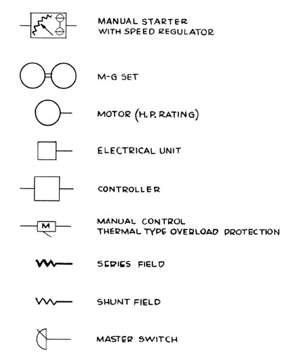
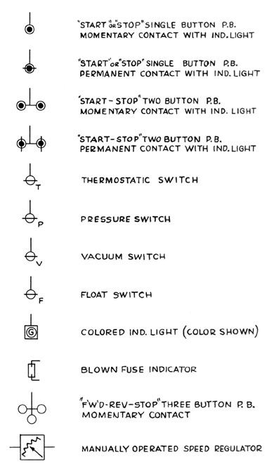
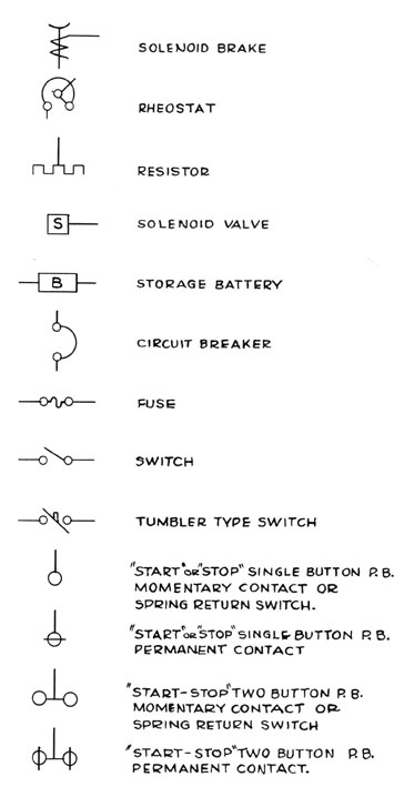
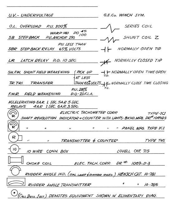
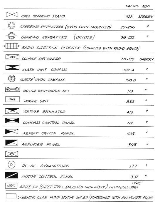
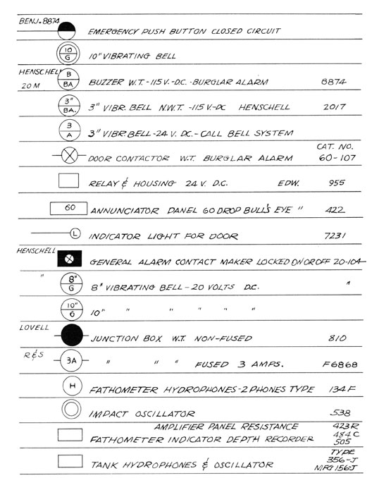
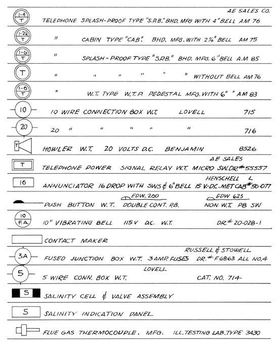
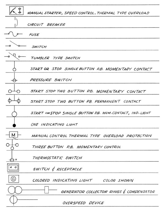
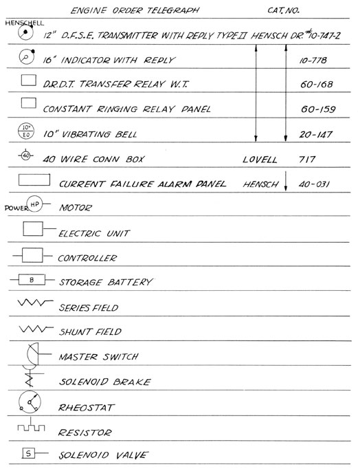
I. Symbols used in marine electrical blueprints
140
141
142
143
144
145
146
147
148
II. Color codes used in marine electrical blueprints and wiring
Navy Type
Conductor No
Base Color
Tracer Color
Tracer Color
1
Black
2
White
3
Red
4
Green
5
Orange
6
Blue
7
White
Black
8
Red
Black
9
Green
Black
10
Orange
Black
11
Blue
Black
12
Black
White
13
Red
White
14
Green
White
15
Blue
White
16
Black
Red
17
White
Red
18
Orange
Red
19
Blue
Red
20
Red
Green
21
Orange
Green
22
Black
White
Red
23
White
Black
Red
24
Red
Black
White
25
Green
Black
White
26
Orange
Black
White
27
Blue
Black
White
28
Black
Red
Green
29
White
Red
Green
30
Red
Black
Green
31
Green
Black
Orange
32
Orange
Black
Green
33
Blue
White
Orange
34
Black
White
Orange
35
White
Red
Orange
36
Orange
White
Blue
37
White
Red
Blue
38
Brown
39
Brown
Black
40
Brown
White
41
Brown
Red
42
Brown
Green
43
Brown
Orange
44
Brown
Blue
149
Telephone Twisted Pair Code #22
Twisted pair color code: When furnished as twisted pair, the following color code shall apply:
Pair Number
One Wire
Other Wire
1
Blue
White
2
Orange
White
3
Green
White
4
Brown
White
5
Slate
White
6
Blue/white
White
7
Blue/orange
White
8
Blue/green
White
9
Blue/brown
White
10
Blue/slate
White
11
Orange/white
White
12
Orange/green
White
13
Orange/brown
White
14
Orange/slate
White
15
Green/white
White
16
Green/brown
White
17
Green/slate
White
18
Brown/white
White
19
Brown/slate
White
20
Slate/white
White
21-40
First twenty repeated
Red
41-60
First twenty repeated
Black
61-80
First twenty repeated
Red/white
81-100
First twenty repeated
Black/white
101-120
First twenty repeated
Red/black
121-140
First twenty repeated
Black/orange
141-160
First twenty repeated
Black/green
161-180
First twenty repeated
Black/brown
181-200
First twenty repeated
Black/slate
Capacitance. The capacitance of a 50-foot twisted-pair sample, after
first drying for 4 hours at 30° C., and then followed by exposure for
24 hours to 30° C. and 90 per cent relative humidity, shall not exceed 2500 micro-microfarads at 1000 cycles per second. When the
capacitance measurements are made, the sample shall be removed from
the coil frame used for humidification purposes, and tested either
in a straight length or in such position as to avoid errors due to
too close proximity of any one portion of the test specimen to any
other portion (such as might be introduced were adjacent loops to
touch in a closely coiled specimen).
150
Telephone Twisted Pair Code #22 (continued)
Insulation resistance. The direct current insulation resistance
(between conductor) of a 50-foot twisted-pair sample, after exposure for 24 hours to conditions of 30° C. (86° F.) and 90 percent relative humidity, shall be not less than 1,000 megohms. The
insulation resistance measurements shall be made immediately following the capacitance measurements.
#22 Single Wire Telephone Code. Single conductors shall be furnished
in the following colors, as required: