The Torpedo Directors Mk 27 Mods 1 to 9 are somewhat similar in appearance, function, and
operation. They all calculate torpedo course and transmit torpedo course order and gyro angle
order electrically to the torpedo course indicators at the torpedo tube mounts. Since Mods 4 and
5 are the most numerous modifications, they will be described in detail. The difference between
the other mods and the Mods 4 and 5 are explained in table 1 page 12.
Physical Appearance
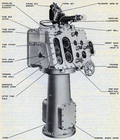
The torpedo director consists of two main assemblies: (1) the rotating case and (2) the stand.
See figures 26 and 27.
The rotating case contains all the dials and the hand cranks, supports the Telescope Mk 50 Mods
0 and 1, supports the crossline rheostat unit, and houses the computing mechanism of the
director. The stand supports the rotating case and houses the power supply selector switch and
the illumination transfer switch. See figure 28.
The torpedo director together with the telescope is approximately 5 feet 6 inches high from the
deck. The rotating case is approximately 3 feet 9 inches wide by 2 feet 5 inches from the front
to the back. The stand is approximately 14 inches in diameter with an 18-inch base flange.
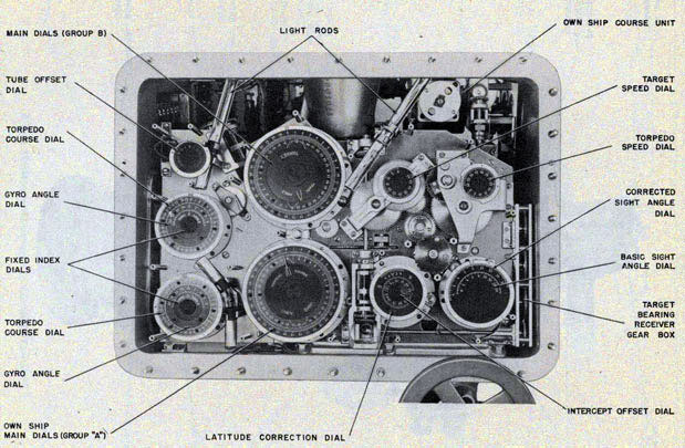
The front of the case consists of a large cover plate which has glass covered openings that give
view to the own ship and target main dial groups "A" and "B" respectively, the tube offset dial,
the torpedo course and gyro angle dials for forward and after torpedo tube mounts, the torpedo
and target speed dials, and the latitude correction, intercept offset and sight angle dials. See
figure 29. Also on this same cover are the input hand cranks for tube offset, target
speed, torpedo speed, intercept offset, target course, and latitude correction.
The training handwheel is located below the latitude correction knob. Mounted on the left side
of the case are the fuse box and the gyro angle hand crank. On the right side of the case are the
own ship course hand crank and dials, the high-and low-speed zero reader dials, the bearing receiver, and a lightwell which provides illumination for these dials.
The telescope pivot which supports the telescope and the firing key is mounted on top of the case.
The crossline illumination rheostat, mounted on the top of the case controls the intensity of
illumination for the crossline of the telescope. Four lightwells, two mounted on the top and two
on the bottom of the case, provide illumination for the various dials on the front of the case.
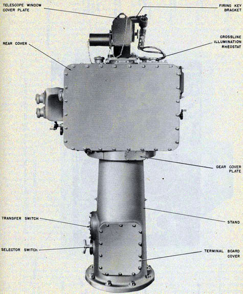
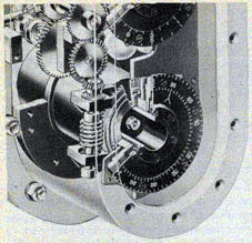
A large cover on the rear of the case, when removed, provides access to the internal mechanism. See figure 28.
Component Parts
The principal assemblies of the torpedo director are: (1) the rotating case, (2) the computer,
(3) the own ship course assembly, (4) the transmitter, (5) the back post, (6) the bearing
receiver, (7) the crossline illumination rheostat, (8) the telescope pivot, (9) the hand crank
assemblies, (10) the dial assemblies, and (11) the stand.
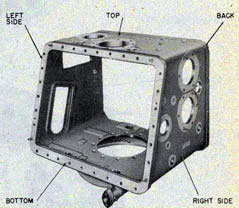
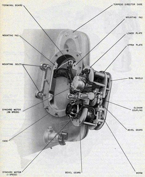
Rotating Case. The cast aluminum-alloy case,
figure 30, forms the watertight housing for the
computer, the transmitter and the own ship course units. In addition, the case forms a rectangular platform for the mounting of the bearing receiver and telescope.
The front side of the case is made up entirely of a cover secured to the frame of the case by
studs and acorn nuts. Glass covered openings have been provided in the front cover for the tube
offset, torpedo course and gyro angle dials for the forward and after torpedo tube mounts,
31
TORPEDO FIRE CONTROL EQUIPMENT (DESTROYER TYPE) OP 1586
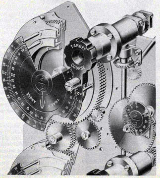
Figure 27- Front left view Torpedo Director Mk 27 Mod 5.
32
DESCRIPTION-DIRECTOR
Figure 28-Back view of Torpedo Director Mk 27 Mod 5.
33
TORPEDO FIRE CONTROL EQUIPMENT (DESTROYER TYPE) OP 1586
Figure 29-Front view of director case, cover and dial shields removed.
34
DESCRIPTION-DIRECTOR
own ship and target main dial groups "A" and "B", torpedo and target speed dials and sight angle,
intercept offset and latitude correction dials.
The training handwheel, located below the lower-right front side of the case, is connected by
means of shafting through the base of the case to the training worm. See figures 26 and 50.
The right side of the case contains glass covered openings for own ship course dials And the
zero reader dials. This side also contains pads which support the sight angle and the own ship course
hand cranks. The bearing receiver assembly is attached to this side of the case. See figures 26 and 53.
The left side of the case contains the fuse box cover, secured by wing nuts for ready removal.
Spare fuses are stored inside the cover. This side of the case also contains the generator access
opening cover which provides mounting for the gyro angle hand crank. See figure 27.
The back side consists of a large blank cover which is secured to the case frame by acorn nuts
and studs. On this same side, is a small cover which provides access to the spur gear (mounted
on the BTO-2 shaft) that meshes with the fixed training gear of the stand.. See figure 28.
The top side of the case contains the crossline illumination rheostat, two lightwells and the
telescope pivot.
A total of five lightwells, each equipped with two Navy type TS-20 6-8 volt bayonet-base type
lamps, are mounted on the case and provide illumination for the various dials.
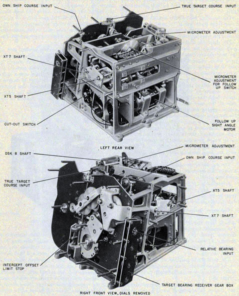
Computer Assembly. The computer is the largest assembly in the rotating case. It occupies at
least two-thirds of the interior space. The computer as a unit receives six inputs: (1) torpedo
speed, (2) target speed, (3) target course, (4) own ship course, (5) latitude correction and
intercept offset, and (6) relative target bearing.
The mechanical portions of this unit make use of these inputs to calculate torpedo course order
which is sent mechanically to the transmitter unit.
The computer automatically compensates for any or adjustment made in any of the six inputs.
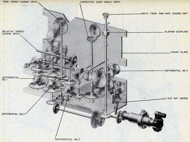
The computer assembly consists of nine separate units or sub-assemblies: (1) chassis, (2)
angle-solver assembly, (3) sight-angle (follow-up) motor, (4) follow-up switch, (5) back
plate assembly, (6) differential gear box, (7) shafting and gearing, (8) stop mechanisms, and
(9) heating unit. These nine units or sub-assemblies are described in the following paragraphs.
See figures 31 and 148.
CHASSIS. This cast aluminum-alloy unit is the frame to which the various sub-assemblies of the
computer are attached. The chassis is roughly cubical in form. The front portion, directly back
of the main dial group, slopes backward from the base at an angle of 15 degrees. Six mounting
lugs extend beyond the bottom members of the chassis and provide the means for securing the
chassis to the bottom of the rotating case. See figures 31 and 37.
Figure 30-Rotating case.
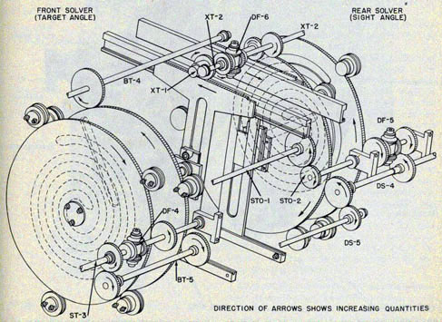
ANGLE SOLVER ASSEMBLY. This assembly is made up of two solvers, each consisting of a cam, a
vector gear, a pin and follower, and one T rack supported between front and back solver plates.
Each cam has a constant lead spiral groove. These cam plates are called the speed gears because
they are turned until the desired target speed and torpedo speed are in alignment with the
respective dial settings. One revolution of the cam plate is the equivalent of 20 knots. See
figures 32 and 33.
35
TORPEDO FIRE CONTROL EQUIPMENT (DESTROYER TYPE) OP 1586
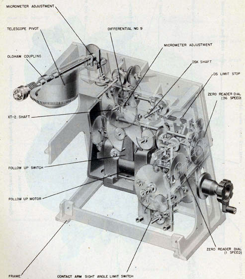
Figure 31-Front and rear views of computer assembly.
36
DESCRIPTION-DIRECTOR
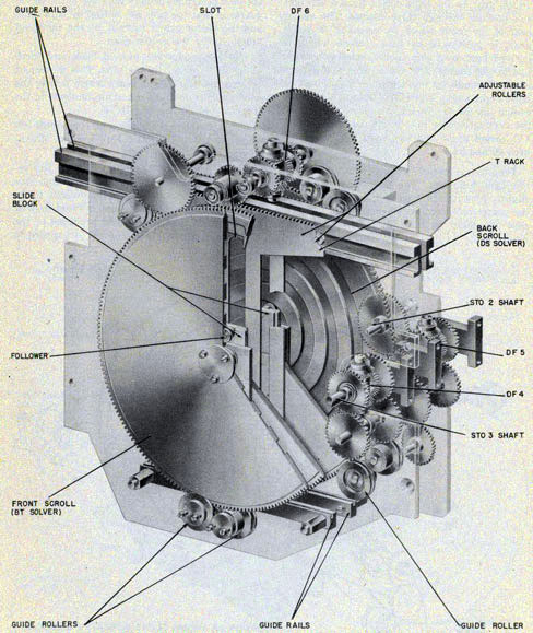
The vector gear in the front solver and the vector gear in the back solver have a straight slot
passing through their centers. The vector gear of the front solver, by means of its input gear, is
positioned by target angle which is derived from own ship course, relative bearing and target
course. The vector gear of the back solver, through its input gear, is positioned by basic sight
angle. Therefore, the angle that the center line of the vector gear slots make with the vertical
center line of the solver represent (1) target angle and (2) sight angle. See figures 10 and 33.
The pins are joined to blocks which also carry the cam followers. The followers are offset
slightly from the pins so that the pins are over the center of the cams, when the followers are
near the inner ends of the cam grooves. See figure 33.
The followers ride in the cam grooves and the pins protrude through the slots in the vector
gears, so that the pins are moved by both cams and the vector gears, radially by the cams and angularly by the vector gears.
The two racks are pushed back and forth along their guides by the pins. This movement rotates
the two output gears which deliver the solved components to other mechanisms in the director
via differential DF-6.
For a complete description on component solvers, see OP 1140, Basic Fire Control Mechanisms.
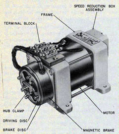
SIGHT ANGLE (FOLLOW-UP) MOTOR. This reversible motor is of the induction-capacitor type.
The rotor is not connected directly to the power supply but has current induced in it by the
action of a magnetic field produced by the stator coils when 115-volt A. C. is supplied to
Figure 32-Diagram of angle solver assembly.
37
TORPEDO FIRE CONTROL EQUIPMENT (DESTROYER TYPE) OP 1586
Figure 33-Cutaway view of angle solver assembly showing gearing and shafting between front
and back scrolls.
38
DESCRIPTION-DIRECTOR
Figure 34-Sight angle (follow-up) motor.
Figure 35-The follow-up switch controls direction of motor rotation.
the coils. The motor's principal function is to drive the vector gear of the back solver assembly
and the telescope. The motor drives the back solver, producing target deflection (Xt) until it
equals torpedo deflection (Xto). When these two quantities are equal the correct sight angle to
solve the torpedo control problem is produced and the servo motor stops. This sight angle
positions the telescope in relation to the rotating case, through an angle equal to the sight angle.
See figures 34 and 40.
In case of casualty to the ship's electrical power causing the sight angle motor to become
inoperative, the sight angle hand crank can be engaged to take over the sight angle drive.
Rotation of this crank also positions the vector gear of the back solver and the telescope.
FOLLOW-UP SWITCH. This switch controls the power supply to the sight angle motor causing it
to rotate in either direction. See figures 35 and 36.
This follow-up switch is operated by the output of the differential DF-6, that is, by the
difference between Xt and Xto.
When Xt is greater than Xto, the contacts of the follow-up switch are closed, energizing the
sight angle motor so that it rotates in a direction that will drive the vector gear until Xt equals
Xto. When Xt is smaller than Xto, the contacts are closed to operate the motor in the opposite
direction so that the vector gear is driven to increase Xt until it equals Xto. See figure 10.
The output of DF-6 sent to the follow-up switch, operates an intermittent gear drive of this
unit. A segment attached to the intermittent gears moves a mutated pinion gear connected on a
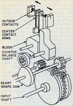
shaft with the signal cam. See figure 36. The rotation of the pear shaped signal cam raises and
lowers a cam follower and contact block which is connected to the center contact arm and causes
the arm to move to the right or left and form a contact with the stationary outer contacts.
BACK PLATE ASSEMBLY. The cast aluminum alloy frame of this assembly contains in its base the
sight angle follow-up motor. Extended interior brackets, above the base, provide support and
bearing for the back plate gear train,
39
TORPEDO FIRE CONTROL EQUIPMENT (DESTROYER TYPE) OP 1586
Figure 36-Operatng diagram of follow-up switch.
driven by the sight angle motor, that furnishes motion to the telescope pivot gears and the
gears of the back solver assembly. See figures 37 and 40.
DIFFERENTIAL GEAR Box. The differential gear box assembly consists of three bevel-gear type
differentials: DF-1, DF-2, and DF-3, which are supported between the top and bottom plates of
the differential gear box. See figure 39.
Differential DF-4 is the compensating differential for the front solver. It receives and sends
target speed to the spiral cam and maintains the radial displacement of the cam follower
constant for any given speed regardless of the movement of the vector gear.
Differential DF-5 is the compensating differential for the back solver. It receives and sends
torpedo speed to the spiral cam and maintains the radial displacement of the cam
follower constant for any given speed regardless of the movement of the vector gear.
Differential DF-6 compares its inputs of Xt and Xto and sends the difference between the two
inputs to operate the follow-up switch.
SHAFTING AND GEARING. The balance of the computer shafting and gearing, not previously
described, can best be explained by examination of the gearing diagram. See figure 148: Also
refer to figures 33, 38, 39, and 40.
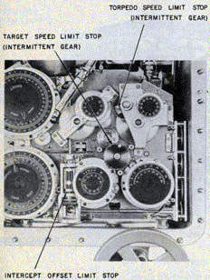
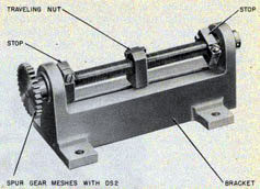
STOP MECHANISMS. There are three types of stops in the computer assembly: (1) traveling nut
or screw type, (2) contact-arm switch type, and (3) intermittent gear type limit stop. See
figures 38 and 41.
The traveling nut stop consists of a bracket with two vertical posts, a traveling nut, which
extends into a slot in the bracket, a threaded screw and two adjusting stops. There are two
traveling nut type stops in the computer assembly. One stop is mounted on the back plate of the
computer and stops the telescope from training in excess of 70 degrees in relation to the
rotating case and the other traveling nut stop is on the front plate and stops the inner dial
of the
intercept offset group from turning in excess of 25 degrees. See figure 42.
The contact arm switch type (sight angle) consists of two pivited contact arms and two
stationary contact points secured between front and back reinforced bakelite plates. An actuating
pin protruding from the limit switch actuating gear revolves and depresses either of the
pivoted contact arms, which break the electrical circuit to the sight angle (follow-up) motor.
The stopping of the motor limits the sight angle that can be produced to 70 degrees and prevents
the telescope from turning in azimuth beyond 70 degrees with relation to the case. See figure
40.
The intermittent gear type limit stop assembly consists of a bronze flower-shaped driven gear
and a toothed driver gear to which is attached a small stop. See figures 38, 41, and 62. The
small stop makes contact with a pin on the inside of the assembly cover plate. The intermittent
stop for the target speed gear train has a one-tooth drive gear. This stop is used to prevent
the cam follower, in the spiral groove of
40
DESCRIPTION-DIRECTOR
Figure 37-Back plate removed from computer assembly.
41
TORPEDO FIRE CONTROL EQUIPMENT (DESTROYER TYPE) OP 1586
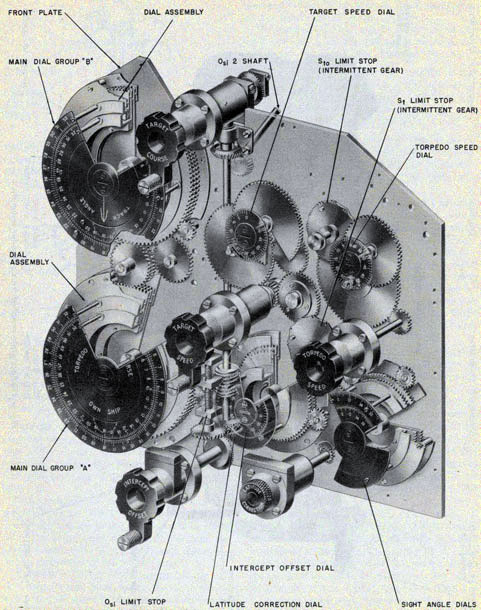
Figure 38-Cutaway of dials, gearing and computer front plate.
42
DESCRIPTION-DIRECTOR
Figure 39-Cutaway of computer showing differential gear assemblies.
43
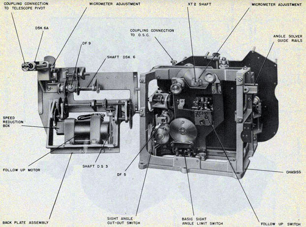
TORPEDO FIRE CONTROL EQUIPMENT (DESTROYER TYPE) OP 1586
Figure 40-Cutaway of computer shafting and gearing showing shafting connection to telescope pivot and sight angle limit switch.
44
DESCRIPTION-DIRECTOR
the back solver, from jamming at either end of the groove.
The intermittent stop for the torpedo speed gear train has a three-tooth drive gear. This stop
prevents the cam follower, in the spiral groove of the front solver, from jamming at either end
of the groove.
HEATING UNIT. This unit is located in the
rear of the computer assembly on the lower
left side. The unit is composed of resistance wire wound around an inverted porcelain cone.
When installed the resistance ought to be approximately 70 ohms on 115 volts current is 1.6 amps. The heater is Used to warm Up the mechanism of the torpedo director in extremely cold
weather. See figure 43.
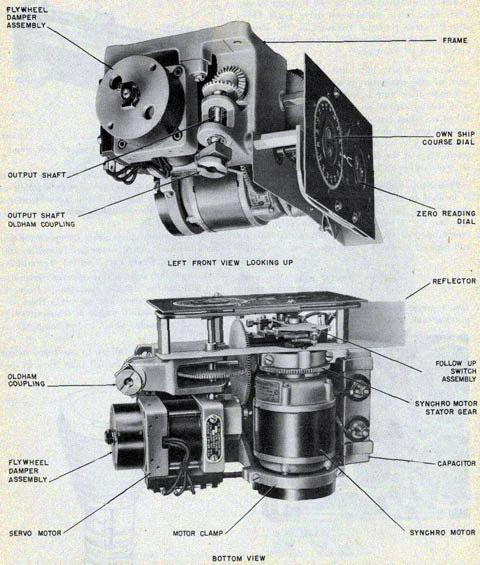
Own Ship Course Assembly. This assembly is located in the upper right hand corner of the
rotating case and is secured to the top of the case. The assembly consists of a rectangular frame
open at the back and top, a dial shield and bracket containing the one-speed own ship
Figure 41-View of director limit stop mechanisms.
735193-47-4
Figure 42-Traveling nut type of limit stop.
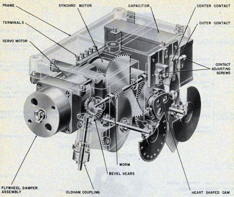
Course and zero reader dials, the type 5B synchro motor with a heart-shaped cam follow-up switch assembly and a 115-volt a-c servo motor complete with damper and reduction gear. See
figures 44 and 46.
For a complete description on operation and function of a synchro motor and follow-up unit. see
OP 1140, Basic Fire Control Mechanisms.
The own ship course unit receives continuous own ship course signals, electrically, from the
gyro compass system and converts them into a mechanical output which is transmitted by means
of a coupled shaft to the computer assembly.
In case of power failure to the servo motor. own ship course can be fed into the own ship
Figure 43-Heating unit.
45
TORPEDO FIRE CONTROL EQUIPMENT (DESTROYER TYPE) OP 1586
Figure 44-Own ship course assembly showing relationship of synchro and servo motors.
46
DESCRIPTION-DIRECTOR
course unit by the use of the hand crank on the right side of the rotating case.
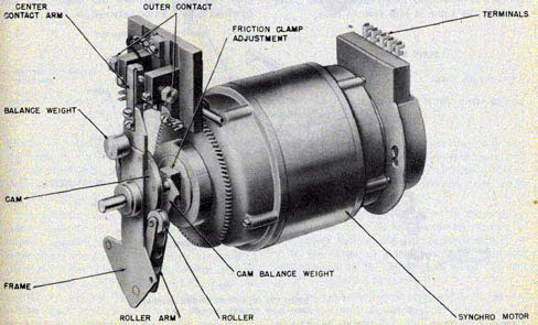
SYNCHRO MOTOR TYPE 5B. This motor consists of a stator, rotor, case, inertia damper, two
bearing caps, and brushes. In addition, a heart-shaped cam follow-up switch assembly is ball-bearing mounted on the rotor shaft. The one-speed zero reader dial is attached to the rotor shaft
of the synchro motor. The main purpose of this dial is to show when the own ship course signal, received by the synchro motor has been executed. When the synchro motor receives a signal,
the dial is displaced from its zero position. As the signal is executed, the zero reader dial is
restored to its original zero position, that is, the index of the dial is lined up with the fixed index of the dial plate.
The synchro motor receives own ship course signals, electrically from the gyro compass system. These signals displace the rotor. As the rotor turns it displaces the heart-shaped follow-up switch from its zero position and causes an electrical contact to close and energize, via a
capacitor, the servo motor.
Although synchro motors transmit extremely accurate signals, their outputs must be boosted
considerably before they can drive heavily loaded shafts. The reason is that the torque delivered
by synchro falls off sharply as the rotor approaches the point of synchronism. As the rotor
nears the point of zero error, the induced current in the stator coils is rapidly reduced,
seriously affecting the ability of the synchro motor to drive a heavy load. At the point of zero
error, torque becomes zero. Accordingly, the synchro motor is used as a control for the servo
motor that drives the actual shaft load to the computer assembly. For a complete description of
synchro motors, see op. 1303, United States Navy Synchros.
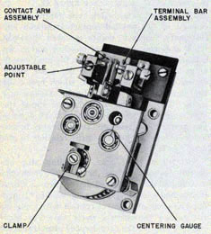
The heart-shaped cam follow-up switch assembly consists of a follower arm, follower roller
and spring, and a heart-shaped cam. The spring keeps the follower roller seated firmly in the
valley of the heart-shaped cam. See figure 45. The cam functions when a signal causes the rotor
of the synchro motor to turn while the power to the servo motor is shut off. In this case, the
synchro motor would turn, rotating
Figure 45-View of own ship course assembly synchro motor and follow-up switch showing friction adjustment.
47
TORPEDO FIRE CONTROL EQUIPMENT (DESTROYER TYPE) OP 1586
the center contact arm against the outer contact arm. To prevent possible damage to the contacts,
the arm carrying the center contacts is not attached directly to the rotor shaft, but is fixed to
the heart-shaped cam. This cam is ball-bearing mounted on the rotor shaft so that it can turn freely.
Whenever the rotor is turned by an incoming signal, the follower arm must turn because it is
keyed to the rotor shaft. As the follower arm turns, the follower roller is pulled around. The
roller being firmly seated in the valley of the heart-shaped cam, pulls the cam around with the
roller. When the cam is rotated, the center contact is brought against the outer contact and the
servo motor starts to drive.
As the signal continues to come in from the gyro compass system faster than the servo can
drive, the rotor of the synchro motor continues to turn and carry the follower-arm around with
it. The follower roller is now forced up and out of the valley, and rides around the heart-shaped
cam pressed to the cam by the action of the spring. So, although the center contact is now held
firmly against the outer contact, the rotor is still free to turn.
Now the rotor can turn until the follower roller reaches the peak of the cam without disturbing
the contacts. This means that if the servo power is shut off, a considerable input can be
transmitted to the synchro motor without throwing the system out of synchronism.
When the stator of the synchro motor is rotated, the rotor is turned back toward the position
from which it started, and the follower roller becomes again seated firmly in the valley of the
cam through the action of the follower spring. The contacts are not yet separated so the servo
motor keeps driving the stator around. As the rotor is turned still farther, the heart-shaped cam
is moved around by the follower aim. The contacts separate and the servo motor ceases to drive.
See figures 36 and 45.
The inertia damper assembly, -consisting of -flywheel (friction drum), brake blocks and
adjusting screws, is ball-bearing mounted on the end of the synchro motor rotor shaft. See
figure 47. The inertia damper is attached to the synchro motor to prevent hunting or oscillation
as the matched or zero position is reached. The only connection between the motor and the
flywheel is by friction between the brake blocks
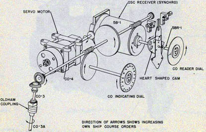
Figure 46-Diagram of own ship course assembly shafting and gearing.
48
DESCRIPTION-DIRECTOR
Figure 47-Cutaway of own ship course assembly showing heart-shaped corn, follow-up switch, dials gearing servo motor and capacitor.
and the friction drum. As the motor tends to accelerate or decelerate, part of the inertia of
the flywheel will attempt to prevent speed changes. The friction may be adjusted by turning the adjusting screws.
The 1/200 hp capacitor induction type servo motor consists of a rotor. stator, two end frames,
capacitor, and inertia damper. The rotor shaft runs in ball bearings mounted in the end frames.
The ends of the stator shell fit into the end frames and four bolts hold the assembly together.
One end of the rotor shaft carries the inertia damper, while the capacitor is attached to the frame
of the own ship course unit. See figure 47. The servo motor takes the
own ship course signals from the own ship course synchro motor and converts them into
mechanical motion powerful enough to drive, through a reduction gear, the computer mechanism.
The servo motor is of the induction type, that is, the rotor is not connected directly to the power
supply, but has current induced in it by the action of a magnetic field. This field is produced by
the stator coils when 115 volt A. C. is supplied to them.
If no capacitor were used and both coils of the servo stator were connected directly across the
power supply line, the rotor of the servo motor would not revolve but would merely
49
TORPEDO FIRE CONTROL EQUIPMENT (DESTROYER TYPE) OP 1586
Figure 48-Right front and left front views of transmitter.
50
DESCRIPTION-DIRECTOR
Figure 49-Left rear and right rear views of transmitter.
51
TORPEDO FIRE CONTROL EQUIPMENT (DESTROYER TYPE) OP 1586
remain stationary, unless actually given a push in either direction. Without a capacitor, this
type of motor has no starting torque of its own. However, when current from the supply line is
made to pass through the capacitor before it reaches one of the coils (while the outer coil
remains directly connected) the rotor will revolve. The direction of rotation will depend on
which coil is supplied through the capacitor.
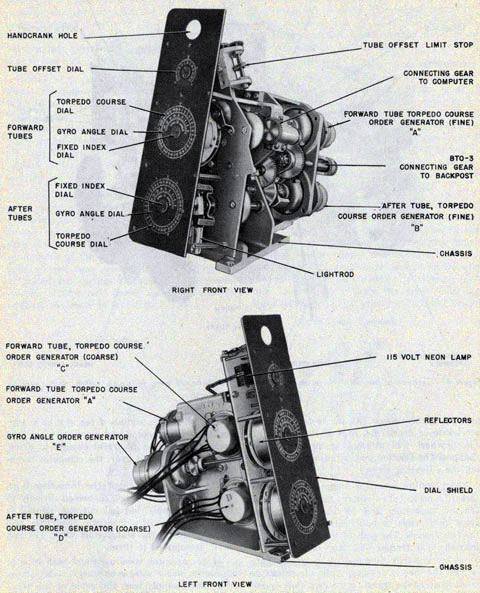
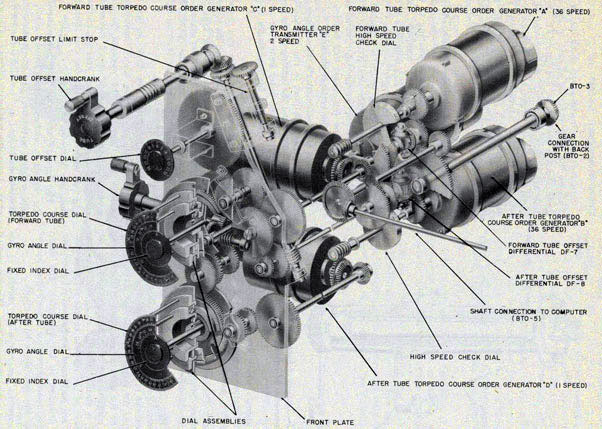
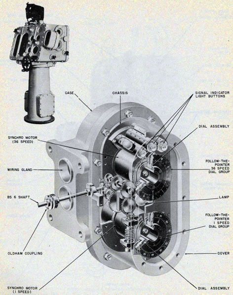
Transmitter Unit. This unit, located along the left side of the rotating case, consists of a chassis,
five synchro generators, differentials DF-7 and DF-8, two torpedo course and gyro angle dial
groups and two 36-speed check dials. See figures 48, 49, and 50.
The transmitter assembly, as its name implies is used to convert a mechanical input of torpedo
course and gyro angle into electrical
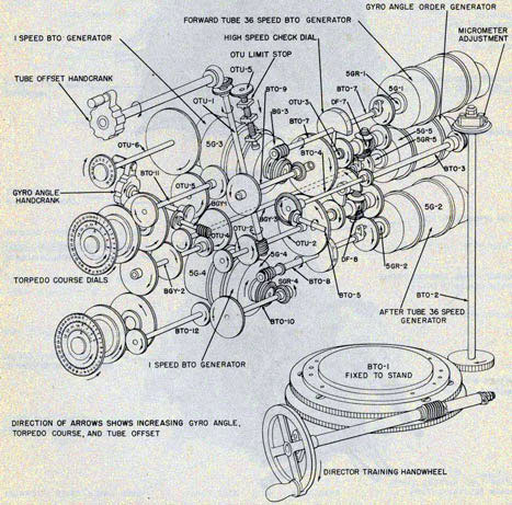
Figure 50-Diagram of transmitter shafting, gearing and synchro generators.
52
DESCRIPTION-DIRECTOR
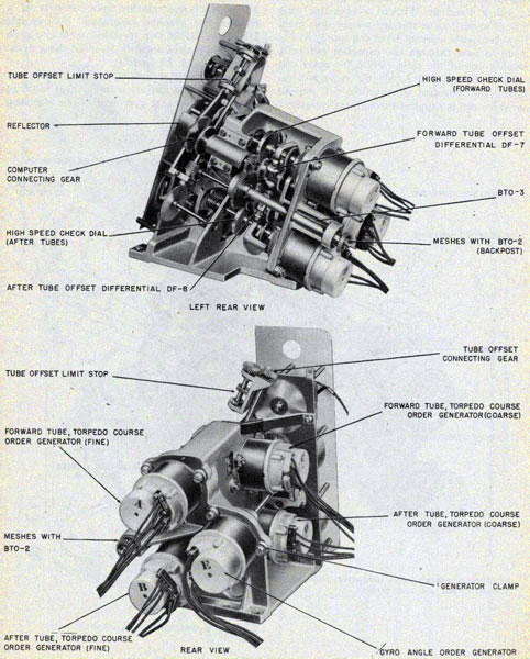
Figure 51-Cutaway of transmitter showing gear connection to back post (BTO-2 shaft). The transmitter unit drives through the back post to rotate the case on the director stand.
53
TORPEDO FIRE CONTROL EQUIPMENT (DESTROYER TYPE) OP 1586
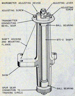
Figure 52-Cutaway of back post (BTO-2 shaft) showing micrometer adjustment and connecting gear.
output signals which are sent to the torpedo course indicators at the fore and after torpedo tube
mounts. See figure 146.
CHASSIS. The cast aluminum chassis supports the synchro generators, gearing, shafting, the
dials, and the differentials.
SYNCHRO GENERATORS. There are five synchro generators, Type 5G, in this assembly. These
consist of two sets of one-and 36-speed generators for torpedo course and a two-speed
generator for gyro angle. Each of these generators consists of a rotor that is coupled to the
gearing, a stator, collector rings and brushes. The rotors of the torpedo course synchro
generators are positioned mechanically by torpedo course produced in the computer. The rotor
of the two-speed generator is positioned by rotation of the gyro angle hand crank.
The synchro generators are secured to the chassis with generator clamps. For a complete
description of synchro generators; see OP 1303, United States Navy Synchros.
CHECK DIALS. One 36-speed check dial is located on the rotor shafting of each of the 36speed
synchro generators. See figure 51. These dials are graduated every 10 minutes and numbered
every degree from 0 to 10, thus one revolution of the dial represents 10 degrees. The dials are
used mainly for test and adjustment purposes. To read these dials, the gyro angle cover on the
left side of the case must be removed.
Back Post (BTO-2 Shaft Assembly). This assembly, extending through the bottom of the case, is
connected by means of gearing to the shafting of the transmitter, computer, and training circle
assemblies. Examinations of figure 52 shows that the shaft is encased in a circular flanged
housing which is attached to the bottom of the director case. Attached to the shaft is an upper
micrometer adjustment gear which rests on the felt-sealed ball bearing at the upper end of the
vertical housing.
The results of the computer's calculations are relayed via the back post to the transmitter,
while at the same time the turning of the lower gear, meshing with the outer gear ring of the
training circle, positions the case to the upper sight angle.
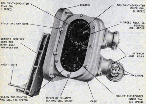
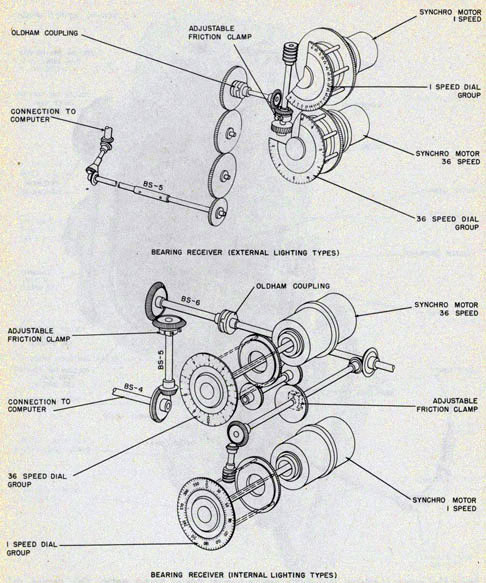
Bearing Receivers. There are two general types of bearing receivers used with the torpedo
director: (1) the external lighting type and (2) the internal lighting type. See figure 56. The
external lighting type, the production model, is described first and the internal lighting type
last on pages 54-55.
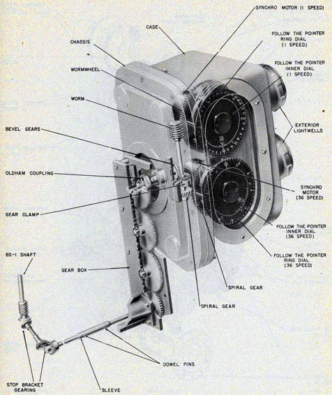
EXTERNAL LIGHTING TYPE. This bearing receiver consists of a case which houses the chassis
that supports the one-and 36-speed synchro motors, one-and 36-speed follow-the-pointer dial
group, reduction gearing, shafting and two external lightwells for dial illumination. See figure
53.
The Type 1F synchro motors are secured to the chassis by motor clamps. These motors receive
relative target bearing signals electrically at one-and 36-speed, and position the inner dials of
the follow-the-pointer dial group. The outer
54
DESCRIPTION-DIRECTOR
or ring dials are positioned mechanically by rotation of the training handwheel of the director.
The inner dials of both sets have a center index with 10-minute graduation marks on either
side. The one-speed ring dial is graduated every degree and numbered every 10 degrees from 0
to 360. The last zero is omitted from the dial graduations so that a reading of 23 represents
230 degrees. The 36-speed ring dial is graduated every degree from 0 to 10 degrees.
Figures 54 and 55 show the construction of the bearing receiver and how the parts are arranged.
INTERNAL LIGHTING TYPE. This unit was built especially for use with the Torpedo Director Mk 27 Mods 1, 4, and 5 as a stop-gap until the regular production units, previously described,
could be supplied in quantity. It was manufactured in two almost identical designs
by the Mare Island Naval Shipyard. Torpedo Directors Mark 27 Mods 1, 4, or 5, equipped with
either of the two internal lighting type designs, are designated by the mod numbers 7, 8, or 9,
respectively. Only the original design will be discussed herein in detail.
This unit is also located on the right front side of the rotating case and operates in the same way
as the production unit. See figures 57 and 58 for the original design and BuOrd Sketch 118287 for the later design of internal lighting type units.
The synchro motors of the internal lighting type unit are secured in a casting which is parallel
to the front face of the director.
Note: The front cover of this unit can be removed only from the front while the production unit
cover can be removed only from the light side of the director. See figures 53 and 57.
Figure 53-External lighting type bearing receiver with gear box connection to computer mechanism.
55
TORPEDO FIRE CONTROL EQUIPMENT (DESTROYER TYPE) OP 1586
Figure 54-Right side and rear view of external lighting type bearing receive; showing terminal block and wiring connections.
56
DESCRIPTION-DIRECTOR
Figure 55-Cutaway of external lighting type bearing receiver showing synchro motors, dials, gearing, and shafting.
57
TORPEDO FIRE CONTROL EQUIPMENT (DESTROYER TYPE) OP 1586
Figure 56-Diagram showing the differences between the gearing and shafting of the external and internal lighting types of bearing receivers.
58
DESCRIPTION-DIRECTOR
Figure 57-Internal lighting type bearing receiver partially removed from case to show wiring and shaft connection to computer mechanism.
59
TORPEDO FIRE CONTROL EQUIPMENT (DESTROYER TYPE) OP 1586
Figure 58-Cutaway of internal lighting type bearing receiver showing indicating signal lamps gearing and dial details.
60
DESCRIPTION-DIRECTOR
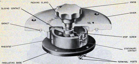
Figure 59-Cutaway of crossline illumination rheostat showing sliding contact and rheostat coil.
The three small indicator lights on the dial face are not now connected to the target
designation or fire control systems of modern destroyers. Signal devices, external to the bearing receiver, are
used to provide mark signal indication.
The later design unit is similar in operation and appearance to the original design except that
there are only two small indicator lights on the dial face. See BuOrd Sk 118287. These lights,
marked "MARK" and "ON", are connected to the target designation system in accordance with
BuOrd Sk 118299.
Crossline Illumination Rheostat. This rheostat is mounted on the top of the rotation case to the
left of the telescope. It is used for varying the intensity of the illumination of the telescope
cross wires to suit external light conditions. The three light positions are "BRIGHT", "DIM", and "OFF".
Figure 59 shows the construction and arrangement of the crossline illumination rheostat.
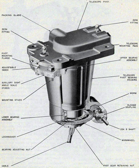
Telescope Pivot. This assembly, made of cast bronze or aluminum, is mounted in the top of the
torpedo director by a flange and forms the pedestal for the Telescope Mk 50 Mod 0 or 1. The
major portion of the pivot extends down into the rotating case. See figure 60. The
735193-47-5
assembly consists of an outer housing and an interior pivot and telescope base, two circular ball-
bearing assemblies-one at the top and one at the bottom-a worm gear assembly, a bottom cable
sleeve and three watertight outlets for the electrical cables. The interior pivot and telescope
base rotates 140 degrees within the outer housing which is supported on upper and lower
bearing assemblies.
The telescope pivot is geared to the output shaft of differential DF-9 and is therefore turned
through the calculated corrected sight angle with respect to the rotating case.
A fixed azimuth scale, attached to the outer housing, is graduated every degree and numbered
every 10 degrees from 295 through 0 degrees to 65 degrees and may be used to read the approximate sight
angle. See figure 60.
Hand Cranks. There are five types of hand cranks used for introducing inputs into the director:
(1) training hand-wheel type, (2) own ship course and sight angle type, (3) target course,
tube offset type, (4) latitude correction hand knob type, and (5) intercept offset type.
TRAINING HANDWHEEL TYPE.-The four-spoke training handwheel, located in the lower right
portion of the case, is secured to one end of the training shaft. Near the other end of the training
shaft a worm meshes with the training
61
TORPEDO FIRE CONTROL EQUIPMENT (DESTROYER TYPE) OP 1586
Figure 60-Cutaway of director telescope pivot showing telescope mounting pods, auxiliary sight angle scale, worm and wormwheel.
62
DESCRIPTION-DIRECTOR
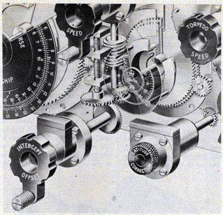
Figure 61-Cutaway of the torpedo speed and own ship course hand cranks and the latitude correction knob.
63
TORPEDO FIRE CONTROL EQUIPMENT (DESTROYER TYPE) OP 1586
worm wheel fixed to the top of the stand. Rotation of this handwheel trains the rotating case,
each complete revolution of the wheel moves the case two degrees. See figure 50.
OWN SHIP COURSE AND SIGHT ANGLE TYPE. The hand cranks for own ship course and sight angle inputs have small solid wheels with projecting
knobs. The assembly consists of a steel shaft, brake spring, adjustable friction clamp pressure
plate, friction washers and latch housed in a light aluminum casting. The inner end of the steel shaft
contains a drive gear, gear adjusting clamp, and detent.
If electrical power fails, own ships course and sight angle inputs can be introduced into director
by simply lifting the latch and pushing in the hand crank. This action engages the drive gear with the
computer mechanism and the detent opens the cut-out switch which permits manual operation of the hand crank. See figure 61.
The cut-out switch opens the electrical circuit to the servo motor and thus prevents the servo motor from rotating if power is restored while the hand crank is in the engaged position.
One complete revolution of either hand crank cranks two degrees of sight angle or own ship course
into the director.
TARGET COURSE TYPE. The hand cranks for target course, tube offset, target speed, torpedo speed,
and gyro angle consist of a solid wheel with projecting knob, steel shaft, brake spring, brake
cylinder screw, adjustable friction clamp and gear adjusting screw housed in a light aluminum casting.
The handwheel assemblies vary slightly in length and drive gear design. See figure 61.
One revolution of the target speed and torpedo speed hand cranks is equivalent to two knots each.
One revolution of the tube offset hand crank introduces two degrees, the target course hand crank four
degrees, and the gyro angle hand crank five degrees.
LATITUDE CORRECTION TYPE. The latitude correction knob assembly consists of a solid knurled
knob attached to a steel shaft and drive gear and an automatic detent and latch spring housed in an
aluminum casting. The detent rides over
a toothed latch cylinder and turning the knob causes the detent to click in passing over the
cylinder teeth. Each click represents one-sixth degree correction. Each complete revolution of
the knob is equivalent to two degrees of latitude correction. See figure 61.
INTERCEPT OFFSET TYPE. This hand crank is similar to the target course type. This type
contains a toothed latch cylinder similar to the latitude correction hand crank.
Dial and Dial Gear Assemblies. The torpedo director, complete with bearing receiver, contains a
total of 13 dial assemblies plus two check dials.
All of the dials, with the exception of the own ship course, sight angle, check dials, and the
relative target bearing inner dials are positioned by hand crank inputs. The sight angle and own
ship course dials can be positioned either by servo motors or by hand cranks. The
Figure 62-View of shaft driven single dial assembly showing details of intermittent type limit stop.
64
DESCRIPTION-DIRECTOR
Figure 63-View of two dial type assembly.
check dials are positioned by torpedo course as produced in the director. The relative target
bearing inner dials are positioned by the synchro motors in the bearing receiver.
The one-speed own ship course dial is driven mechanically by the output of the servo motor or
by rotation of the own ship course hand crank. The dial is graduated every two degrees and
numbered every 20 degrees from 0 to 360. The last zero has been omitted from the dial
graduation, so a reading of "20" represents 200 degrees. When this dial is read against the fixed
index, it indicates the amount of own ship course that has been set into the computing mechanism.
Dials that are driven mechanically by gearing and shafting are classified into four different
dial arrangements: (1) single dial driven by a shaft, (2) two dial type, (3) three dial type, and (4)
follow-the-pointer dial type.
The single dial type consists of a dial driven by a shaft. The dial is black with white
translucent engraved figures. The single dial type is used for tube offset, target speed, torpedo
speed, own ship course, and high-and-low speed zero reader dials. Figure 62 shows the arrangement
of a typical single dial type.
The two dial type consists of an inner dial driven by a shaft and a ring dial driven by gearing.
This type of dial arrangement is used for latitude correction and intercept offset and corrected
sight angle and basic sight angle. Figure 63 shows the arrangement of a typical two dial type.
The three dial type consists of an inner dial driven by a shaft, a middle ring dial driven by
gearing and an outer ring dial also driven by gearing. This type of dial assembly is used for
the own ship and target main groups "A" and "B" and the torpedo course and gyro angle group. In this
last group, the center or inner dial is a fixed dial and therefore does not rotate. Figure 64 shows
the arrangement of a three dial type.
65
TORPEDO FIRE CONTROL EQUIPMENT (DESTROYER TYPE) OP 1586
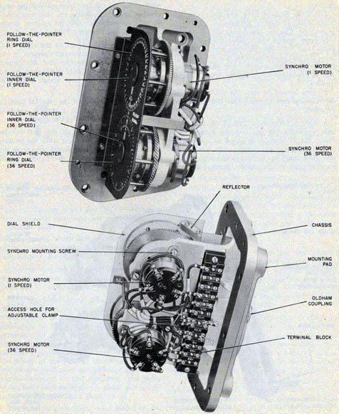
The follow-the-pointer dial group consists of an inner dial positioned by the rotor of the
synchro motor and a ring dial driven by gearing. Two of these groups are used in the bearing
receiver. One group operates at one-speed, the other at 36-speed. Figure 65 shows a typical
arrangement of the follow-the-pointer dial group.
These inner dials are attached directly, by means of dial clamps and hubs, to the ends of the
rotor shafts of the synchro motors.
A summary of the information given above is tabulated in table 3 page 67.
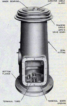
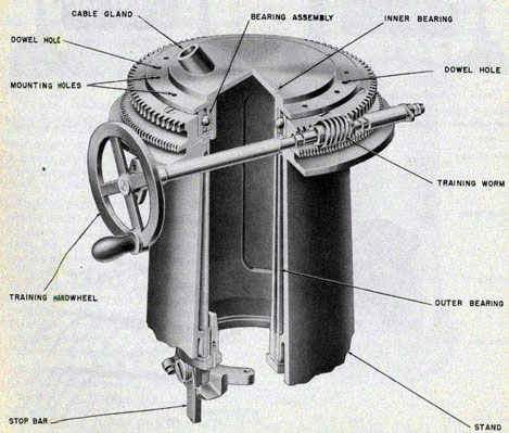
Director Stand. This unit is roughly cylindrical in form and is bolted, by a bottom flange, to the
bridge deck or to a raised director mount platform. The stand provides a ball-bearing base for
the torpedo director case. A training circle, secured to the top of the stand, meshes
with a worm driven by the training handwheel attached to the director case. The rotation of the
training handwheel turns the case with respect to the stand. This rotation is limited by
mechanical stops to approximately 390 degrees. See figure 66.
A cable clamp, bolted to the stand, anchors the lower end of the 60-conductor cable leading to
the distribution panel in the case. The cable extends through a gland in the upper part of the
stand. All twist in the cable is taken up between the clamp and the gland when the torpedo
director case is trained. See figure 67.
In the lower portion of the stand are two rectangular terminal board access covers and mounting
pads for the transfer and selector switches. In the flanged base of the stand are six watertight
terminal tubes which admit the ship's wiring. In the lower base will be found a six-volt a-c lighting transformer.
Figure 64-View of gear driven three dial type assembly.
66
DESCRIPTION-DIRECTOR
TABLE 3
Dial Name
Type
Number of Dials
Turn Equivalents
Gear
Shaft
One
Two
Three
Tube Offset
X
X
1 turn equals 80 degrees
Target Speed
X
X
1 turn equals 60 knots
Torpedo Speed
X
X
1 turn equals 60 knots*
Own Ship Course, indicating
X
X
1 turn equals 360 degrees
Own Ship Course, zero reader
X
X
Zero Reader, low speed
X
X
1 turn equals 360 degrees
Zero Reader, high speed
X
X
1 turn equals 10 degrees
Bearing Receiver, one-speed inner dial
X
X
1 turn equals 360 degrees
Bearing Receiver, 36-speed inner dial
X
X
1 turn equals 10 degrees
Bearing Receiver, one-speed ring dial
X
X
1 turn equals 360 degrees
Bearing Receiver, 36-speed ring dial
X
X
1 turn equals 10 degrees
Latitude Correction and Intercept Offset
X
X
turn equals 60 degrees
Basic Sight Angle and Corrected Sight Angle
X
X
1 turn equals 360 degrees
Own Ship Main Dial Group "A" Relative Target Bearing True Target Bearing and Corrected Sight Angle
X
X
1 turn equals 360 degrees
Target Main Dial Group "B" True Target Bearing Target Angle and Corrected Sight Angle
* One turn equals 60 knots for Mods 3, 4, 5, 6, 8, and 9.
One turn equals 50 knots for Mods 1, 2, and 7.
67
TORPEDO FIRE CONTROL EQUIPMENT (DESTROYER TYPE) OP 1586
Figure 65-View of follow-the-pointer dial assembly.
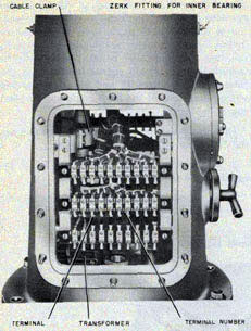
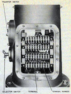
TERMINAL BOARD. Interior mounting brackets hold seven terminal blocks which connect the
director electrical circuits to the ship's wiring. See figures 67 and 68.
TRANSFER SWITCH. The transfer switch, mounted on a pad on the base of the stand, provides
convenient changing of the illumination supply from the 115-volt a-c ship' circuit to a storage
battery located near the director. The switch positions are "OFF", "BATTERY", "OFF" and "TRANSFORMER". See figure 68.
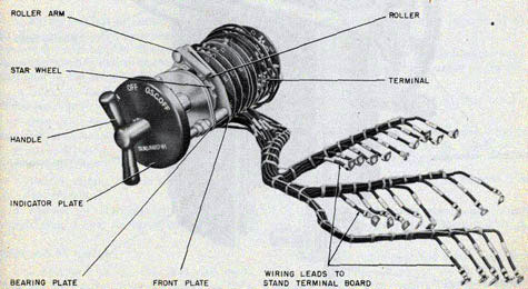
SELECTOR SWITCH. A three-position rotary selector switch on the stand controls all director
circuits except the firing circuits, torpedo course and gyro angle orders. At the "ON" position
the director is fully energized, at the "OSC OFF" position all circuits, except those for own ship
course, are energized. At "OFF" position all controlled circuits are deenergized. See figure
69. If it is necessary to maintain the director in a stand-by condition set the selector switch to "OSC
OFF". This will prevent wear to the own ship course unit.
TRAINING CIRCLE AND STOP. This assembly consists of an inner bearing, outer bearing, bottom
plate, stop, training gear, and an upper ball-bearing support. The circle is connected, by
gearing, to the director train shaft and hand crank. Movement of the hand crank rotates the
director case while the stand remains stationary. This stop limits the train of the rotating case
to 390 degrees. See figure 70.
Gearing (Mechanical Diagrams)
Examination of figures 149 and 150 will show the differences in gearing between Torpedo
Director Mk 27 Mods 1, 3, 4, 5, 7, 8 and 9, and Torpedo Director Mk 27 Mod 2.
SYSTEM ELECTRICAL COMPONENTS
The wiring diagrams consist of external and internal diagrams. The external wiring diagrams
are the GA, 6PA, and 6R circuits and the internal wiring diagrams are for the Torpedo Director
Mk 27 and the Torpedo Course Indicator Mk 1.
Figure 66-Director stand with terminal board cover removed to show terminal tubes.
68
Figure 67-View of bottom of director stand showing front terminal boards, cable clomp, and transformer.
Figure 68-View of back terminal boards in stand.
Figure 69-Selector switch assembly showing star wheel, roller arm, and wiring leads.
69
TORPEDO FIRE CONTROL EQUIPMENT (DESTROYER TYPE) OP 1586
GA Circuit
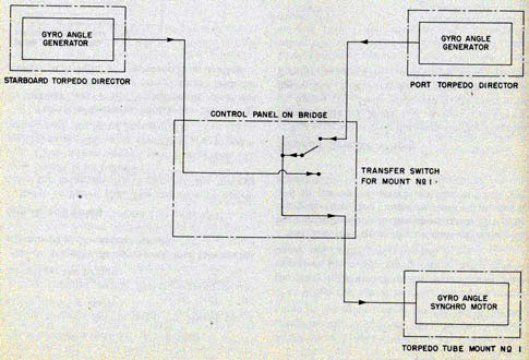
This circuit, shown on figure 151, is subdivided into the gyro angle system (circuit 1GA),
the torpedo course system (circuit 2GA), and other miscellaneous circuits (GA, 7GA. 24GA, and 27GA).
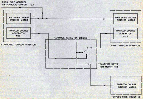
The torpedo course and gyro angle systems comprise the port and starboard torpedo directors, a
transfer switch and associated fuse and overload indicator panel on the bridge, and an indicator
at the tube mount.
Refer to figure 151. When the bridge transfer switch is turned to "STBD" position, the
starboard torpedo director controls the tube mount. When turned to "PORT" position, the port
torpedo director controls the tube mount.
When the switch is turned to either of the previous positions, the forward (No. 1) torpedo
course and the gyro angle synchro generators in the selected director are connected, through the
fuse and indicator panel, to the synchro motors in the torpedo course indicator at the tube
mount. Figures 71 and 72 are simplified wiring diagrams of the gyro angle and torpedo course systems, respectively.
On ships fitted with two torpedo tube mounts the following additional is provided:
1. A transfer switch for Mount No. 2 located on the bridge.
2. A torpedo course indicator at the second tube mount.
Figure 70-Training circle at top of director stand showing stop mechanism.
70
DESCRIPTION-SYSTEM ELECTRICAL COMPONENT
Figure 71-Torpedo control system-circuit 1GA, simplified wiring diagram.
3. Wiring suitable to connect the after (No. 2) torpedo course and gyro angle synchro
generators in each torpedo director to the corresponding synchro motors in the torpedo course
indicator at the second tube mount.
In addition, each torpedo director has the following inputs:
1. Own ship course (circuit 7GA) from the fire control switchboard.
2. Servo motor supply (circuit GA) from the I.C. switchboard.
3. Heater supply (circuit 27GA) from the 1.C. switchboard.
4. Six-volt D.C. (circuit 24GA) illumination supply from a local storage battery
6PA and 6R Circuit
The 6PA and 6R circuits, shown on figure 152, are the torpedo firing and ready light circuits.
The torpedo firing system (circuit 6PA) consists of:
1. Portable two-circuit contact makers adjacent to and the firing keys mounted on the torpedo directors.
2. A torpedo control panel at the director station.
3. A transfer switch on the bridge. This is the same switch referred to on pages 68 to 71 for
circuit 1GA and 2GA.
4. A torpedo firing panel at the torpedo tube mount.
5. The 120-volt 60-cycle power supply from the I.C. switchboard and a 120/20-volt firing transformer.
The torpedo ready light and battle order system (circuit 6R) consists of the same contact
makers, firing keys, control panel, transfer switch, and firing panel used in circuit 6PA.
71
TORPEDO FIRE CONTROL EQUIPMENT (DESTROYER TYPE) OP 1586
On ships fitted with two torpedo tube mounts the following additional is provided:
1. A torpedo control panel for Mount No. 2 at the director station.
2. A transfer switch for the second mount located on the bridge.
3. A torpedo firing panel and associated equipment at the second mount.
Signals and Firing
Refer to figure 152. The sequence of operations for firing the No. 1 panel of the torpedo tube
mount is as follows:
1. Close power supply switches at the I.C. switchboard. This also energizes the primary winding
of the firing transformer.
2. Turn the transfer switch on the bridge t "STBD" or "PORT" position to select the controlling station. This energizes the transfer h pilot light at the controlling station.
3. Close the snap switch for No. 1 Barrel on the control panel at the director station. This
energizes the indicator light in the control panel in the mount panel for the No. 1 Barrel.
4. When the barrel is ready for firing, close the ready light switch on the mount panel. This
energizes the mount ready lights in the mount panel and in the control panel.
5. Close the firing key or contact maker at the control station to fire the barrel. This also
energizes the "fire" light in the control panel and in the mount panel and the horn at the
mount.
Torpedo Director Wiring
The internal wiring diagram for the Torpedo Director Mk 27 Mods 1, 3, 4, and 5 is shown on
figure 153. Mods 7, 8, and 9 are shown on figure 154. For Torpedo Director Mk 27 Mod 2 refer to figure 155. Additional transmitters,
Figure 72-Torpedo control system-circuit 2GA and 7GA, simplified Wiring diagram.
72
DESCRIPTION-INDICATOR
for sending information to the central group of torpedo tubes are required for Torpedo Director Mk 27 Mod 2.
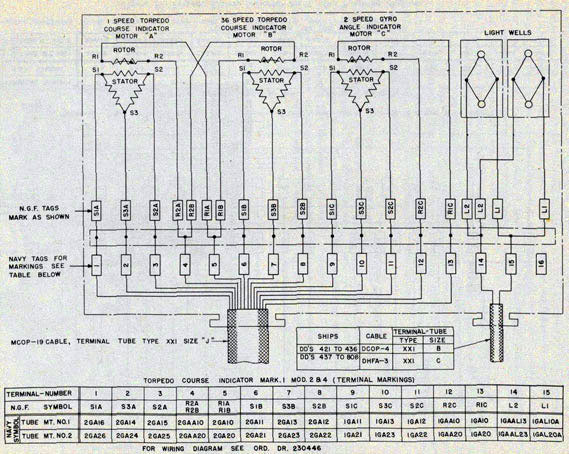
Torpedo Course Indicator Wiring
The internal wiring diagram of the Torpedo Course Indicator Mk 1 Mod 0 is shown on figure 79.
The Torpedo Course Indicator Mk 1 Mod 1 is the same electrically as the Mk 1 Mod 0 except for
the removal of the plug board. L1 and L2 connections are made directly to the main terminal
board as shown on BuOrd Dwg 180609.
The wiring for Torpedo Course Indicator Mk 1 Mod 2 (original design) is shown on BuOrd Dwg
180685. The wiring for the later design is shown on figure 80. Torpedo course indicators
mounted on DD 421 and upward contain no lighting transformers. The wires for the 6-volt
lighting circuit enter the case in a separate terminal tube connecting to terminals 14 and 15 on
the terminal board. The wiring for Torpedo Course Indicator Mk 1 Mod 3 is as
shown on BuOrd Dwg 238028. The wiring for the Torpedo Course Indicator Mk 1 Mod 4 is the same as the later Torpedo Course Indicator Mk 1 Mod 2.
Terminal Board. The terminal board, secured to interior machine pads in the rear of the case,
consists of a single strip with the necessary terminals for connecting the input synchro supply
leads to the synchro motors and the input dial illumination leads to the lightwells. See figure 75.
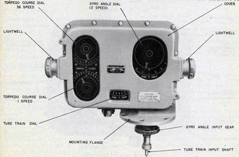
TORPEDO COURSE INDICATOR MK I MODS 0 TO 4
The torpedo course indicator indicates torpedo course, torpedo course order, gyro angle, gyro
angle order, and actual tube train as received mechanically from the training rack of the tube mount.
Mods 0 to 4 are somewhat alike in construction and physical appearance and since the Mod 4
indicator is the production instrument, it will be described in detail. The difference
Figure 73-Front view of Torpedo Course Indicator Mk 1 Mod 4.
73
TORPEDO FIRE CONTROL EQUIPMENT (DESTROYER TYPE) OP 1586
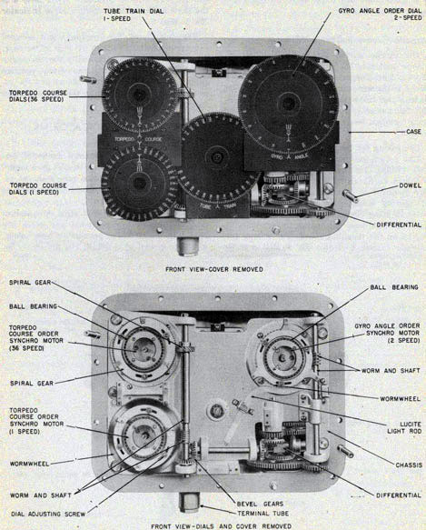
Figure 74-View showing interior details of indicator.
74
DSCRIPTION-INDICATOR
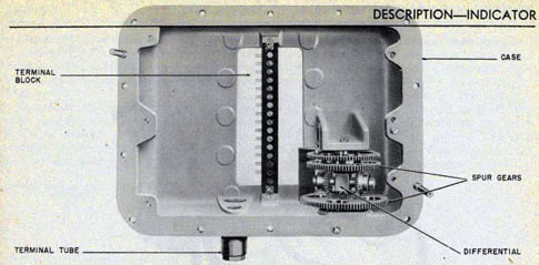
Figure 75-Interior view of indicator showing differential and terminal board.
between Mod 4 and the previous mods are explained in the Introduction chapter, page 13.
In the Mod 3 indicator one major difference occurs. An explanation for this will he given in
later paragraphs of this section.
Physical Appearance
The indicator is approximately 14 inches high (2O 1/4 inches with the input shaft attached), 21 inches wide, and 9 inches thick. See figure 73.
The indicator mounting ring is secured to the torpedo course attachment. Figure 6 shows the
relationship of the torpedo course indicator and the torpedo course attachment.
On the front of the indicator a removable cover contains three glass-covered openings behind
which are located the one-and 36-speed torpedo course dials, the gyro angle dials and the tube
train dial. The dials are illuminated by two lightwells, one mounted on the right and one mounted
on the left side of the front cover.
The tube train output shaft and the gyro angle input gear protrude from the bottom of the
instrument. Two terminal tubes, one for 115-volt synchro supply leads and the other terminal
tube for 6-volt dial illumination supply leads are located in the bottom of the case. Mounted on
the rear of the indicator case is the terminal board cover.
Component Parts
The principal parts of the torpedo course indicator are the case and front cover; chassis, dial,
and motor unit; the differential; input shaft; gearing; and terminal board. See figures 74 and 77.
Case and Front Cover. The cast aluminum alloy case together with the front cover houses the
internal mechanism of the indicator. See figure 73. The case contains two openings, one on the
front side for access to the dial and motor unit and one on the rear side for access to the terminal
board. A flange on the front of the case is used for bolting the front cover to the case.
Inside the case, integral mounting pads and brackets support the chassis which contains the dial
and motor unit and the gearing and shafting.. The indicator is mounted, by means of a circular
flange to the top of the torpedo course attachment.
The aluminum-alloy front cover contains three glass covered openings which protect the dials
of the indicator. The glass windows are kept watertight by means of rubber gaskets.
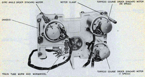
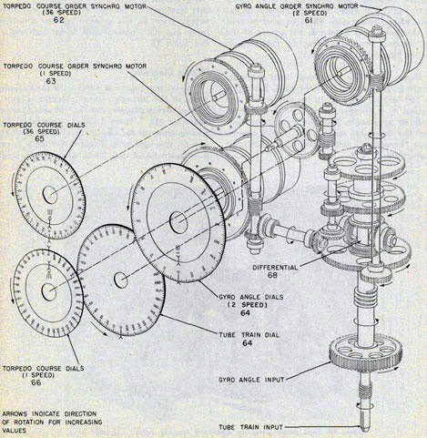
Chassis, Dial, and Motor Unit. The unit consists of a cast aluminum-alloy chassis supporting the
one-and 36-speed torpedo course synchro motors, the torpedo course dials, two-speed gyro
angle synchro motor, gyro angle dials,
75
TORPEDO FIRE CONTROL EQUIPMENT (DESTROYER TYPE) OP 1586
tube train dial and the gearing arid shafting. See figures 74 and 76. An illumination
transformer will be found on the chassis of the Mod 0, 1, and 3 indicators.
The dial and motor unit for the Mod 3 indicator does not include the two-speed gyro angle
synchro motor and follow-the-pointer dials. In the Mod 3 instrument the follow-the-pointer
dials are replaced with a single dial with the same graduations as the follow-the-pointer ring dial.
The three synchro motors, type 5F, are secured to the chassis by motor clamps. The left-hand
side of the chassis supports two torpedo course synchro motors, the 36-speed motor is at the
top and the one-speed motor at the bottom. The gyro angle synchro motor is located in the upper
right-hand side. See figure 76. Attached to the rotor of each of the synchro motors is an inner
dial of one-and 36-speed follow-the-pointer dial group. These, dials, marked by a single index,
are positioned by the electrical signals received by the synchro motors. The ring dials are
positioned mechanically by torpedo course, the output of the indicator differential.
All the dials are black with engraved white translucent figures or graduations. The one-
speed ring dial is graduated and numbered every 10 degrees from 0 to 360. The 36-speed ring
dial is graduated every 5 minutes and numbered every 20 minutes from zero to 10 degrees. To
obtain the correct value of the torpedo course signal from these dials the indexes of the ring
dials must be first positioned to match the indexes of the inner dials and then the graduation of
the ring dials read against the fixed index. See figure 13.
The two-speed gyro angle follow-the-pointer dials consist of an inner dial, positioned
electrically by the director gyro angle signal which moves the rotor of the synchro motor, and a
ring dial positioned by gyro angle received mechanically from the torpedo course attachment.
The ring dial is graduated every degree on either side of zero. On the left of the zero, the dial is
graduated for 85 degrees with every 10 degrees numbered from 0 to 80 degrees. On the right of
the zero the dial is also graduated for 85 degrees with every 10 degrees numbered by the
graduations from 360 to 280 degrees. The value of gyro angle set into the torpedoes is obtained
by reading the ring dial against the fixed index.
The tube train dial is driven mechanically at one-speed by tube train received from the training
76
DESCRIPTION-INDICATOR
rack of the torpedo tube mount. The dial is graduated every two degrees from 0 to 360
degrees. Actual tube train can be seen by reading the graduations of the dial against the fixed index.
To indicate the unsafe firing sector on the tube train dial, the engraved degree markings should
be masked out by application of blue or black enamel or lacquer. The numerals indicating tube
train should be left visible.
The gearing and shafting of the dial and motor unit operate the various mechanical dials. For
example, the torpedo course ring dials are positioned mechanically by gearing, receiving its
drive from the output of the differential. The gyro angle ring dial is positioned mechanically by
gearing, receiving its drive from the gyro angle input gearing. The tube train dial receives its drive from the tube train input shaft by means of gearing.
Figure 77-Torpedo Course indicator Mk Mod 4-schematic mechanical diagram
75193-47-6
77
TORPEDO FIRE CONTROL EQUIPMENT (DESTROYER TYPE) OP 1586
Differential. The bevel gear type of differential is located in the lower right hand part of the
case. Figure 75, shows the construction and arrangement of the various parts of the
differential. The spider of the differential is secured to the tube train input shaft. A spur gear
secured to the upper end of the tube train input shaft transmits tube train to drive the tube
train dials. The lower input bevel gear of the differential, secured to the sleeve that fits around
the tube train input shaft, is driven by gyro angle. The upper bevel gear is the output gear of the differential. The spur gear secured to this bevel gear transmits the output of the
differential, torpedo course, to the torpedo course ring dials. See figure 77.
Input Shaft. The tube train input shaft extends from the bottom of the case. The shaft is ball-
bearing mounted in the differential and guided by a circular sleeve. The sleeve is rotated by gyro
angle. The tube train input shaft and the sleeve are spring-back packed to prevent "breathing"
and to keep the instrument watertight.
Gearing. Figure 77, the gearing diagram for the Torpedo Course Indicators Mk 1 Mods 0, 1, 2, and 4, shows the arrangement of the gearing and shafting. For the Mod 3 indicator the gearing is
the same except that the Mod 3 does not have a two-speed gyro angle order synchro motor.
Terminal Board. The terminal board, secured to interior machined pads in the rear of the case,
consists of a single strip with the necessary terminals for connecting the input synchro supply
leads to the synchro motors and the input dial illumination leads to the lightwells. See figure 75.
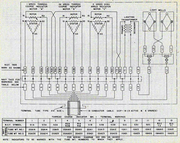
Wiring Diagrams
The wiring diagrams differ with the various mods of the torpedo course indicator. Figure 80,
the wiring diagram for the Torpedo Course Indicator Mk 1 Mods 2 and 4, illustrates the wiring
hook-up for the three synchro motors and the two lightwells. These instruments have a separate
6-volt dial illumination supply and
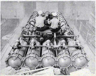
Figure 78-Tube mount personnel operating torpedo course indicator and gyro setting mechanism.
78
DESCRIPTION-INDICATOR
Figure 79-Torpedo Course Indicator Mk 1 Mod 0-wiring diagram.
79
TORPEDO FIRE CONTROL EQUIPMENT (DESTROYER TYPE) OP 1586
therefore do not have an illumination transformer.
An explanation is given on the diagram of the particular wiring differences between the Mod 4 and Mods 0, 1, and 3.
Torpedo Course Attachment Mk I and Mods
The torpedo course attachment mechanically connects the gyro setting mechanism of the torpedo
tubes to the torpedo course indicator and the latter to the indicator training rack on the tube
stand. See figure 6.
For complete description of the Torpedo Course Attachment Mk 1 and Mods, see OP 764, "21 in. A. W. Torpedo Tubes Mk 14, 15 and Mods".
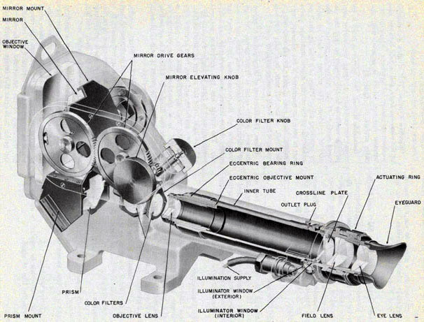
TELESCOPE MK 50 MODS 0 AND 1
Telescope Mk 50 Mods 0 and 1 are used on Torpedo Directors Mk 27. The Telescope Mk 50 Mod
1 is similar to Telescope Mk 50 Mod 0 except that protective covers for the objective window
and eyepiece have been added to the Mod 1. See figures 14 and 81.
Optical Description
These telescopes are monocular, periscopic instruments with the line of sight to the target
located a few inches above the horizontal axis of the eyepiece. The line of sight to the target may
be elevated or depressed 30 degrees above or below the horizontal (strictly speaking, 30 degrees above or
below a line parallel to the deck), to compensate for roll of the ship, so that the target can be
kept in the field of view. The optical
characteristics are:
Magnification
6 diameters
Field of view
8 degrees 30'
Diameter of exit pupil
5 mm
Eye distance
31 mm
The optical system, shown in figure 14 consists of:
The objective window.
A mirror which can be rotated to elevate or depress the line of sight.
A prism.
Color filters.
The objective lens.
A reticle (crossline plate).
Eyepiece (field lens and eye lens).
Objective Window. This window is mounted in the telescope body, and is held between lead
washers or gaskets of synthetic rubber by the window retainer, which is secured with machine
screws. See figure 81.
Rotatable Mirror. This mirror is fitted in its mount by carefully scraping the mirror
supporting surfaces in the mount so that the silvered surface, of the mirror is parallel to the
axis of rotation. The mirror is held in place by retaining clips. There is a bearing shaft on
either side of the mirror mount and these shafts rest in bearings machined in the telescope body
casting, being held in place by cap squares. On the shaft, at the left side, is a gear which is
operated by a knob through an idler gear.
Prism. The function of the prism is to reflect the rays, which enter it from above, through 90 degrees through the objective lens, onto the crossline plate into the ocular, and also to erect the
image of the target, both vertically and laterally. The prism has two reflecting surfaces which intersect
to form an angle of exactly 90o, and the light from the mirror is reflected from these two
surfaces, and then from another surface, into the objective lens. The prism is mounted in a
phosphor bronze casting, on which are two flanges by which it is secured to the body casting.
The prism is held in place in its mount by retaining clips.
Color Filters. There are four filters, namely, red, yellow, light neutral and dark neutral, and
also a clear opening (no filter or glass) in a mount similar in shape to a five-sided pyramid.
This mount is keyed to a shaft projecting through a packing gland in the body casting, with an
operating knob at the outer end.
Objective Lens. This consists of a positive lens of crown glass cemented to a negative lens of flint
glass. This lens forms an image of distant targets on the crossline plate. If there were no mirror
or prism in the system, this image would be inverted both vertically and laterally, but the
effect of the reflections in the mirror and prism is to erect this image in both directions. This lens doublet is mounted in an
81
TORPEDO FIRE CONTROL EQUIPMENT (DESTROYER TYPE) OP 1586
Figure 81-Cutaway view of Telescope Mk 50 Mods 0 and 1.
82
DESCRIPTION-FIRING KEY
Figure 82-Cutaway of Firing Key Mk 19 Mod 0.
eccentric mount, so that the line of sight may be aligned accurately with the keyways.
Reticle (Crossline Plate). This plate is in the focal plane of the objective lens, and serves as a
sealing plate for the interior of the telescope body, since the space between this plate and the
eyepiece cannot be sealed tightly, due to the in-and-out movement of the latter. At night the
crosslines may be illuminated by a lamp in Lamp Socket Mk 9, which is secured in a housing on
the side of the telescope body tube. The light enters the telescope through a window and reaches
the crossline plate through a duct.
Eyepiece. The eyepiece or ocular system consists of two cemented doublets which are mounted,
and properly spaced, in the eyepiece draw tube and held in place by a retaining ring. The doublet
nearer the crossline plate is known as the field lens and the doublet nearer the eye is the eye
lens. The eyepiece system can be moved in or out by rotation of the focusing
ring, so that it can be accurately focused on the crosslines and on the image of the target formed
by the objective lens, which image lies in the same plane as the crosslines. The eyepiece may be
focused from plus 2 to minus 4 diopters.
The entrant and emergent surfaces of the objective window, prism, objective lens, and both
lenses of the eyepiece of some of these telescopes (those manufactured since 1942) are coated
with a very thin film of magnesium fluoride in order to reduce the reflection at the surfaces and
thus increase the light transmission of the telescopes. The optical surfaces in those telescopes
which were completed before coating was adopted for this instrument, are being coated when the
telescopes are disassembled in an optical repair shop; ultimately the optical surfaces of all
telescopes in service will be coated. See OP 582 (First Revision) Chapter VIII paragraphs 33-46, for a description of this film and method of removing it.
83
TORPEDO FIRE CONTROL EQUIPMENT (DESTROYER TYPE) OP 1586
Figure 83-Cutaway of Portable Contact Maker Type M-16.
Mechanical Construction
Body. The parts described above are mounted in a phosphor bronze casting. See figure 81. There
is a bore in the casting in which the inner tube fits without play, and also machined surfaces
both inside and outside, for mounting the various other parts. There are four accurately
machined feet, or lugs, whereby the telescope is mounted on the torpedo director.
Mounting Feet. On the bottom of the two feet on the right side of the telescope (as viewed from
the eyepiece end) are accurately machined keyways which are parallel to the line of sight to the
target. These keyways fit over the two parts of an interrupted key on the torpedo director so
that, when the telescope is bolted in place, it is properly aligned and no further adjustment is
necessary. The keyways
in the telescope feet and the keys should not be touched with a tool or abrasive, and the fit should
not be altered, as the keyways in any telescope are intended to fit accurately over the keys on
any torpedo director, so that the telescopes are interchangeable without error or misalignment.
These telescopes are airtight, so that there is no leakage when tested with an internal pressure
of 8 pounds per square inch. The telescopes are, charged with dry gas, usually nitrogen. A
charging valve is located in that part of the body casting which houses the mirror and there is
an outlet valve in the vicinity of the eyepiece.
These telescopes are of rugged construction and the internal parts should require no attention
over a long period of time.
Firing Key Bracket. The firing key bracket is a phosphor bronze casting bolted to the top of the
telescope body. At one end of this bracket is a bore into which Firing Key Mk 19 fits and is
secured by means of a thumb screw.
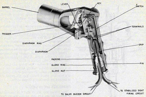
FIRING KEY MK 19 MOD 0
The Firing Key Mk 19 Mod 0 is inserted in a bracket on the left side of the Mk 50 Telescope. See
figure 8. The bronze firing key is constructed in the form of an automatic pistol. The barrel
portion of the key is inserted and fastened in the telescope mounting bracket. In place of a pistol
trigger the director trainer squeezes a spring loaded key (contact maker) when he has trained
the telescope crosslines on the target and is ordered to close the circuit.
A flexible leather diaphragm around the movable key prevents moisture from entering the
interior. The electrical supply wires are packed as they enter and leave the key to keep the
interior mechanism dry and watertight.
The firing key consists of a housing (pistol grip) which encloses the electrical switch and
supports the key. Figure 82, a cutaway view of the firing key illustrates the construction of the
key and the arrangement of the internal parts.
Movement of the key is transmitted by means
of a lever which closes the contacts of the switch. When the key is released a spring forces the
key outward and breaks the electrical contact.
84
DESCRIPTION-FIRING KEY
Four electrical wires are connected to the switch of the firing key; two of the wires are used in
the torpedo firing circuit and the remaining two are used in the ready light circuit. When the
firing key is closed, both the firing circuit and the ready light circuit are closed or energized at
the same time. See figure 152.
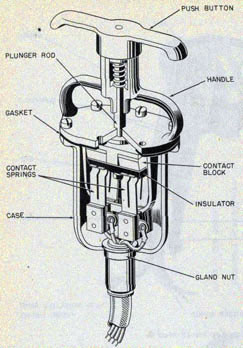
Portable Contact Maker Type M-16
The portable contact maker is used as an alternate method for firing the torpedo. It is
connected in parallel with the firing key of the director and, when closed, energizes both the firing
circuit and the ready light circuit. The
cabling is sufficiently long to allow the user to cross to the other side of the bridge.
The contact maker is of the plunger type. It is mounted in a holder on the director splinter
shield, inboard side. See figure 1. Figure 83 shows the appearance and construction of the contact maker.
The contact maker is operated by gripping the top section of the case with the fingers and
forcing the spring loaded plunger down with the palm of the hand. The release of the tension on
the plunger will automatically open the contact again.
The contact maker is under the cognizance of the Bureau of Ships and is shown on Bureau of Ships Plan No. 9-S-4835--L.