|
PART IV
MAINTENANCE
401. ROUTINE MAINTENANCE.
(a) The following policy of routine inspection and overhaul has been
established:
|
Whenever possible and according to circumstances:
(1) A routine inspection of the ECM at a regularly established ECM Repair
Facility, every 30
days.
(2) A routine complete overhaul of the ECM at a regularly established ECM
Repair Facility
every twelve months.
|
(b) Between these inspections and overhauls there are certain operations
which must be
performed by the operator. This section of these instructions is designed
as a guide for the
operator of the ECM, who must necessarily be responsible for the daily
maintenance and up-keep of the ECM. Only a small amount of time is necessary to insure that
the machine is
properly maintained. Some maintenance duties must be performed daily,
others require only a
few minutes each week. A machine which is properly maintained will give a
minimum of
trouble.
402. LUBRICATION.
(a) The Spare Parts Box (ENG 109) issued with each machine supplies oil,
grease and a one
drop oil can.
(b) (1) Plates 3 and 4 are included to assist in locating the oil holes of
the various units. It
will be noted that, in many of the parts, felt wicks have been provided to
receive the oil rather
than the bearing surfaces of the parts themselves.
(2) CARE SHOULD BE TAKEN TO PREVENT OIL OR GREASE FROM GETTING ON THE CODE
WHEELS,
INDEX WHEELS, CIPHER UNIT, SEPARATORS, CONTROLLER AND KEYLEVER CONTACTS AND
WIRING.
(c) Oil the following points sparingly, once every two weeks.
|
See Plate |
| (1) Stepping Pawls and Stepping Pawl latches - one drop. |
3(c) |
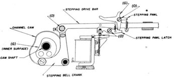
| (2) Stepping drive bars - felt wick in rear guide and forward pivot points. |
3(c)
4(a) |
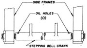
| (3) Stepping bell crank, several drops in oil holes at pivot points. |
4(c) |
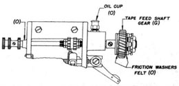
| (4) Tape feed drive; rear bearing - fill oil cup. Front bearing - few |
| drops. |
4(d) |
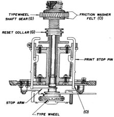
| (5) Friction drive felt washers, several drops on each. |
4(b)
4(d) |
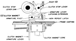
| (6) Clutch magnet armature pivot and clutch stop lever pivot - one drop. |
3(b) |
| (7) Printer stop pins, one drop on tip of each stop pin. |
4(b) |
| (8) Print hammer pivot screw - one drop. |
-- |
| (9) Clutch mechanism - several drops. Ball bearings (two) - few drops. |
3(a) |
| (10) Motor - ball oilers (two). |
-- |
|
| |
-39-
|
|
PLATE 3B - MAIN SHAFT
(Right End View)
|
|
PLATE 3C - CODE WHEEL STEPPING MECHANISM
|
|
PLATE 3
|
| |
-40-
|
|
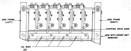
PLATE 4A - CIPHER UNIT CAVITY
|
PLATE 4C - BELL CRANK
(Stepping Mechanism)
|
|
PLATE 4D - TAPE FEED DRIVE
(Right Side of Printer)
|
|
PLATE 4
|
| |
-41-
|
(d) Apply grease sparingly to the following points, once every two weeks
when the machine is in constant use:
|
See Plate |
| (1) Channel cam- inner surface in contact with roller. |
3(c) |
| (2) Stepping pawl, point of contact with reset screw. |
3(c) |
| (3) Tape feed shaft gear. |
4(d) |
| (4) Typewheel shaft gear, reset bail groove. |
4(b) |
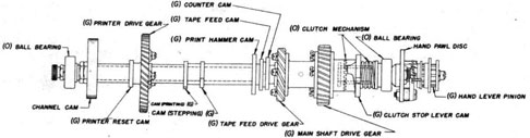
| (5) Printer reset cam, timing cams, print hammer cam, tape feed cam, counter cam, clutch stop lever cam. |
3(a) |
| (6) Printer drive gear, tape feed drive gear, and main shaft drive gear. |
3(a) |
| (7) Motor pinion (on motor shaft). |
--- |
| (8) Controller detent roller and cam surface. |
--- |
| CAUTION: Rub the grease in and clean up any surplus grease which may drop
from the parts
after the machine has run a few minutes.
|
(e) At the time of oiling, (and more often if necessary) wipe the Code
Wheel spindles with an
oily cloth. The Code Wheels must not run on a dry spindle.
403. CLEANING CONTACTS.
(a) Experience has shown that the major cause of unreliable operation is
dirty contacts of the
Cipher Unit. Clean contacts are absolutely necessary for proper functioning
of the machine. The
only reliable method of maintaining clean contacts, except where an
approved Code Wheel
lubricant is used, is to follow a daily cleaning schedule. This will not
only insure the removal of
any dirt which may have been deposited but also will remove any "carried
over" metal which
may have been ground off the contacts.
(b) The lid should be removed only as required for changing Code Wheels,
making Index
Settings, lubrications, etc. It should be kept in place at all other times.
(c) (1) The plunger-contacts of the Cipher Unit must be inspected and
cleaned DAILY, except
where an approved Code Wheel lubricant is used. The Spare Parts Box (ENG
109) contains a
canvas paddle which is especially designed to fit between the Cipher Unit
Separators. The outside
plunger contacts should be rubbed with one side of the canvas paddle.
|
(2) When the canvas becomes soiled, it should be removed and cleaned. If
cleaning solutions are
used it must be rinsed several times in water to insure all cleaning
solution is removed. The
canvas should be stretched tightly when re-assembled on the wooden form.
|
(d) To clean the contacts of the Code Wheels, place a piece of canvas on a
smooth flat surface and
rub the Code Wheel and Index Wheel contacts against the canvas until they
have become clean and
bright. If in some cases the hub of the Code Wheel will not permit the Code
Wheel to lay
completely flat, two blocks should be laid side by side with a space
between them, forming a
depression in which the hub of the Code Wheel will ride, permitting the
Code Wheel Contacts to
lay flat on the canvas,
(e) If, because of infrequent cleaning, the contacts cannot be cleaned with
the canvas paddle, a
pencil (not ink) eraser may be used. The standard flat type, about two
inches long is a
convenient size. It must be clean and free from abrasive material. The use
of the eraser must
always be followed by cleaning with the canvas paddle.
|
| |
-42-
|
|
404. CODE WHEEL LUBRICANT.
(a) A special Code Wheel Lubricant is being made available to all holders.
Initially small
quantities will be forwarded to the Registered Publication Issuing Offices,
as a matter of
convenience in distribution, but regular distribution will be through the
ECM Repair Facilities.
(b) Until the lubricant is available, or if the supply is temporarily
exhausted, the standard
method of cleaning Code Wheels should be followed.
(c) The use of the Code Wheel lubricant requires the cleaning of the Cipher
Unit and Code Wheel contacts at intervals of two four weeks instead of daily.
(d) The approved lubricant is commercially known as "Lubriplate" formula
105.
|
NOTE: "Lubriplate" is extensively used throughout the Navy In connection
with other equipment,
but in most cases It is not formula 105, which is the only type
"Lubriplate" authorized for a
Code Wheel lubricant.
|
(e) "Lubriplate" is light cream in color and has a viscosity similar to
petroleum jelly.
(f) To apply "Lubriplate":
|
(1) Clean the contacts of the Code Wheel, Index Wheel and Cipher Unit in
accordance with
paragraph 403. Wipe the contacts with a clean cloth to insure that all dust
is removed.
(2) Place a very small quantity of "Lubriplate" 105 on the contact surfaces
of the Code Wheels
and Index Wheels. Rub the lubricant into the surface of the contacts.
NOTE: Do not lubricate the contacts of the Cipher Unit.
(3) Polish the faces of the Code Wheels and Index Wheels with a lint-free
cloth. Remove any
excess lubricant.
|
(g) "Lubriplate" should be applied at intervals of two to four weeks,
depending upon use and
local conditions.
(h) THE USE OF ANY OTHER LUBRICANT, OR OF "LUBRIPLATE" IN ANY FORMULA OTHER
THAN
"105" IS NOT AUTHORIZED.
INFREQUENT OPERATIONS
405. PRINTER RIBBON.
(a) A standard 1/2 inch typewriter carbon ribbon (such as used on an
Underwood typewriter)
is used on the Printer. A Hectograph ribbon may be used if preferred.
(b) The ribbon feed Is reversed by moving the ribbon reverse lever towards
the spool upon
which the ribbon is to be wound.
(c) Only one-half of the ribbon is used at a time, and after one-half fails
to print clearly, the
ribbon should be inverted to use the other half. This is accomplished by
reversing the
respective positions of the spools (i.e., the left spool to the right
position and the right spool to
the left position) and replacing the ribbon in the ribbon guide. When
replacing the spools on the
shafts be sure the small pin on the hub of the shaft engages the spool,
thus preventing the spool
from slipping on the shaft.
|
| |
-43-
|
(d) To insert a new ribbon:
|
(1) Allow the ribbon to accumulate on either spool. Disengage the ribbon
from the ribbon guide.
Remove the spools from the shaft by pulling straight out (the spools are
mounted on split
shafts).
(2) Disengage the ribbon from the empty spool, discarding the ribbon and
the spool on which it
is wound.
(3) Engage the new ribbon to the center of the empty spool.
(4) Replace the spools on the shafts so the ribbon runs to the outside of
both spools.
(5) Replace the ribbon in the ribbon guide.
|
406. PAPER TAPE REPLACEMENT.
(a) Paper tape is a "supply" Item and is not normally procurable from ECM
Repair Facilities or
Registered Publication Issuing Offices. In some cases, a small supply of
tape is carried in stock
at these places, but only as an emergency supply. Each ship or station
should anticipate its needs
and order an adequate stock well in advance of actual needs. Activities
from whom paper-tape
can be obtained are as follows:
Stock Maintenance List
Navy Type - 10055
Paper Tape
| Navy Yard or Base |
Maximum Stock
(Rolls) |
Minimum Stock
(Rolls) |
| New York |
40,000 |
5,000 |
| Mare Island |
40,000 |
5,000 |
| Boston |
2,000 |
500 |
| Portsmouth (N.H.) |
500 |
250 |
| Sub-base, New London |
2,000 |
500 |
| Philadelphia |
1,000 |
250 |
| NYD, Norfolk |
500 |
250 |
| NOB, Norfolk |
10,000 |
5,000 |
| Washington |
5,000 |
2,000 |
| Charleston |
2,000 |
500 |
| NS, Key West |
2,000 |
500 |
| NSD, San Juan |
2,000 |
500 |
| NS, Guantanamo |
500 |
250 |
| NSD San Diego |
2,000 |
500 |
| Puget Sound |
10,000 |
5,000 |
| Pearl Harbor |
10,000 |
5,000 |
| NS, Balboa |
1,000 |
250 |
| NS, New Orleans |
1,000 |
250 |
| Sub-base, Coco Solo |
1,000 |
250 |
(b) The paper tape used in the ECM Mark 2 is a special gummed tape made
according to U.S.
Navy specifications. It is not affected by high humidity and will not
become loosened from the
message blank with age. Ordinary 3/8 Inch paper tape (plain or gummed) may
be used in an
emergency, but it is not recommended. Two types of special ECM tape are
available:
| Navy Type No. |
Width |
Layers |
Length |
Groups |
Price |
Rolls to Box |
| CPM 10055 |
3/8" |
1 |
1100 ft. |
18,000 |
$0.15 ea. |
10 |
| CPM 10056 |
3/8" |
1 plus carbon |
500 ft. |
8,000 |
$0.25 ea. |
10 |
|
| |
-44-
|
(c) To replace the paper tape:
|
(1) Raise the tape retainer arm and remove the wooden spool.
(2) Unwind about two turns from the new roll of tape, place the spool of
the tape on the spindle
so the tape roll will turn clockwise when unrolling and replace the tape
retainer into position.
(3) Thread the end of the paper tape through the tape roller (gummed side
up) and into the
cover tape channel with the gummed side out.
(4) Press the tape release tab and push the paper tapes (gummed side down)
between the tape
feed rollers and through the printer tape channel. Release the tape release
tab.
(5) Thread the paper tape around the idler roller.
(6) Examine the "mesh" of the feed rollers; the paper tape should be held
tightly.
|
407. CAUTIONS.
(a) Throughout this publication, several "Cautions" have been Inserted.
Those which affect the
maintenance and upkeep are summarized as follows:
|
(1) The lid should be removed only as required, such as changing Code
Wheels, making Index
Settings, etc. It should be kept in place at all other times.
(2) Code Wheels must be handled carefully, and kept in the box when not in
use. Fingers should
be kept from the contacts as much as possible. The Code Wheels should be
carefully inserted into
the Cipher Unit - the cam-lobe (the "bump" between "U" and "V") is easily
broken off,
rendering the use of the Code Wheel dangerous when used in certain
positions.
(3) Both hands must be used when inserting the Cipher Unit into and
removing it from the
machine, otherwise the Cipher Unit, its frame, or the zeroizing contacts
may be damaged. All
four thumbscrews should be securely tightened.
(4) The pawl and channel ring must be adjusted so the hand drive lever is
free to move up and
down except when actually using emergency power.
(5) The contacts of the Cipher Unit, Code Wheels and machine must be kept
scrupulously clean.
(6) Lubrication instructions must be faithfully followed.
(7) Keep the lamp in the Type 8 Safe Locker on continuously.
(8) The ribbon feed must be reversed by hand.
|
|
| |
-45-
|
|