6-2. The purpose of this section is to provide H8 catapult operating personnel with a guide to assist them in analyzing catapult malfunctions and in determining the correct remedial action. A thorough understanding of the operational characteristics and limitations of the H8 catapult is an essential prerequisite for the proper analysis of its malfunctions. Prior to disassembly of any catapult component, the ship's personnel concerned must familiarize themselves with all details of the part in question. The ship is furnished a complete set of detail plans for this purpose and procedures are given in Section V-Maintenance.
Note
The repair of a failure does not solve a malfunction; the cause of the failure must also be eliminated.
6-3. PREPARATION FOR LAUNCHING.
6-4. GENERAL. Difficulties, which would most likely occur or be first observed when the catapult is being prepared for a series of launchings, are included in this subsection. Also included are difficulties which might occur at any time.
6-5. PUMP DIFFICULTIES. Each ship is furnished with "Operation and Service Handbooks" for their catapult pumps. These handbooks contain full instructions for maintenance of the pumps. A list of these handbooks is given in paragraph 5-32. Malfunctions of the pumps and the remedial action necessary are also given in the applicable manuals.
6-6. EXCESSIVE PUMP NOISE. The pump pressure gage needle will usually fluctuate violently under this condition and in some cases the pump will not deliver accumulator pressure. This condition results either from air in the pump (see pump manual) or an obstruction in the pump suction. A pump should not be allowed to operate under this condition.
6-7. To remove air from the pumps vent the suction line and work the air out of the pump by starting and
stopping motor at intervals of about 10 seconds. If the noise gradually diminishes, continue until all air has been worked out. If this procedure does not reduce the noise, the suction line must be checked for an obstruction. The most likely cause of an obstruction would be either a clogged strainer or a suction line restriction.
6-8. The inability of the bridle tensioning pump to maintain a set pressure or deliver a desired pressure is generally due to a malfunctioning of the pump relief valve. Malfunctioning of the pump relief valve may be due to improper adjustment of the valve. To correct an improper adjustment use procedure given in the pump manuals. If this adjustment fails to correct the malfunction, disassemble the relief valve and clean it thoroughly. If the disc or seat is damaged they shall be replaced. Make certain the relief valve spring is not distorted or fatigued.
6-9. The pump pressure gage installed on each pump and the sound of the pump are the chief guides available to the catapult operator for determining satisfactory operation of the power plant pumps. All catapult operators should become familiar with the normal sound of the power plant units when the pumps are idling, are delivering fluid, or are being changed from one condition to another. When the pump is idling, the pressure gage for that pump should record slightly above zero. When a pump is delivering fluid, its pressure gage should record a pressure slightly higher than that of the accumulator. This condition might vary slightly, however, due to possible variation in gage calibration. The pressure gage needle should not vibrate or fluctuate violently.
6-10. PRESSURE INDICATOR DIFFICULTIES. Complete instructions for maintenance of pressure indicators and corrections of their malfunctions is covered in the manufacturer's manual furnished with each indicator. In addition, each catapult is furnished with indicator repair kits. This will permit all pressure indicator malfunctions to be remedied by the ship's force.
6-11. LOSS OF ACCUMULATOR CHARGE. A rapid drop of launching or retracting accumulator pressure immediately after the power plant pumps are taken off
94
"delivery" is an indication of a check valve in one of the pump discharge lines being stuck open. In order to prevent loss of the accumulator air charge at this time, operate the power plant to maintain the accumulator pressure that existed at the time of the difficulty. The stuck check valve can be identified by listening for the rush of fluid past the stuck check valve when the power plant is idling. Close the pump discharge shutoff valve at the damaged check valve. The pump which discharges into this line must not be operated until the check valve has been replaced. Replace the check valve when conditions permit.
6-12. A sudden continuous drop of retracting accumulator pressure when the retracting button is released is due to failure of retracting valve stem. See paragraph 5-119 for replacement procedures.
6-13. A slow continuous loss of launching or retracting accumulator pressure must be remedied as soon as possible. First check that the securing stem of the piston valve is fully in before searching for possible leaks. If the pressure drop occurs in conjunction with loss of accumulator liquid level a fluid leak is indicated. Otherwise the pressure drop is due to an air leak. Fluid leaks at pipe joints, flanges, etc. which can be checked visually or air leaks which are usually audible shall be repaired as they occur. One other possible cause of loss of fluid from the retracting accumulator would be a leak of the retracting operating valve, retracting valve, the blowdown valve, four-way valve or elbow check valve. By closing the shutoff valve at the four-way valve the source of difficulty can be more closely determined. For the launching accumulator, the cause of fluid loss could be a leak at the piston valve. By closing the shutoff valve to the firing operating valve, the leak can be more closely located. Disassemble leaking valve and replace damaged part. See Section V- Maintenance for replacement procedures.
6-14. A slow continuous rise of retracting accumulator pressure would be due to a leaking air charging valve. It should be repaired at once with the repair kits provided. See paragraph 5-64 for repair procedure.
6-15. STUCK PISTON VALVE SECURING STEM. This difficulty would be apparent when attempting to withdraw securing stem. Make certain the vent valve on the piston valve large head is opened to relieve the piston valve pressure and is kept open while attempting to withdraw the securing stem. If the securing stem cannot be withdrawn normally, close the vent valve and after about ten minutes, attempt to unlock the stem by applying pressure in the opening direction using large wrench. Vent again and withdraw the stem. If this is not successful, the launching accumulator air charge must be blown off. Then loosen
the nuts securing the piston valve head to the valve body so that the head can be wedged out about 1/8 inch. Withdraw the securing stem and then tighten the piston valve head nuts. To prevent the occurrence of this difficulty the securing stem should be turned in with the least torque possible and no force applied once the securing stem disk firmly contacts the piston valve poppet.
6-16. PRE-LAUNCHING.
6-17. GENERAL. This section includes difficulties that might be apparent from the time the "FIRST READY" buttons are depressed until "FINAL READY" lights are obtained. In addition to the items listed below, also check for loose wiring, pushbutton failure, binding relays, or poor relay contacts.
6-18. FIRST READY. Inability to obtain "FIRST READY" lights will be due to one of three causes. In order to obtain the white "FIRST READY" lights when depressing the "FIRST READY" buttons, three switches must be in the normally closed position:
a. The bypass valve interlock switch (RV2) actuated by the bypass valve linkage. This switch also has a normally open contactor in the retracting circuit.
b. The runaway shot preventer switch (CSP) located at the runaway shot preventer valve at the mechanical cutoff mechanism.
c. The constant pressure valve auxiliary dome switch (CPV) located on the end of the air trap cylinder.
6-19. If the white "FIRST READY" lights are not obtained, these three switches shall be checked for evidence of damage and/or correctness of position. If damaged, they shall be replaced before any launching is attempted. Check the action of the mechanical linkage to insure that it has properly actuated the bypass valve interlock switch (RV2). Check the position of the indicator rod of the RSP valve. If indicator rod is out thus holding the CSP switch open, check for sticking rod, obstruction in fluid passages of the RSP valve, or failure of the RSP spring. If the plunger of the air trap cylinder is not fully out to close the CPV switch, add fluid to the 4-inch line (venting line and auxiliary dome of constant pressure valve) until the 4-inch line is completely full of air free fluid and the plunger closes the CPV switch.
6-20. If the white "FIRST READY" lights are obtained by depressing only one "FIRST READY" button, the relay normally actuated by the second "FIRST READY" button is hanging up. The proper procedure for freeing these relays will be found in paragraph 5-9i.
95
6-21. BRIDLE TENSIONING.
a. If, on pressing the bridle tensioning button, nothing happens, then:
1. Contactor button has failed.
2. The bridle tensioning relay is binding in the open position.
3. The RV1 switch is open (bypass valve partly closed, switch out of adjustment, or failed).
4. First ready or standby relay contact point is faulty.
5. Retracting relay is binding partially closed.
b. If, on pressing the bridle tensioning button, the "STANDBY" indicators light and the bridle tensioner solenoid valve is energized but both are lost when the button is released, then:
1. The crosshead is out of battery position.
2. The "X" switch has failed in the open position.
c. If, on pressing the bridle tensioning button, the "STANDBY" indicators light and remain on when the button is released but the bridle is not tensioned, then:
1. The bridle tensioning solenoid valve or operating valve is binding.
2. The bridle tensioning pressure is low or catapult friction is high.
CAUTION
Never fire a catapult with a slack bridle or pendant. Never tension bridle or pendant with shuttle positioner.
6-22. FINAL READY.
a. If, when the final ready button is pressed nothing happens, then:
1. The final ready relay is binding.
6-23. FIRING.
a. If, when the firing button is pressed, nothing happens, then:
1. One set of RV1 switch contacts is faulty.
b. If, when the firing button is pressed the "FIRE" indicator lights but nothing else happens, then:
1. One set of "X" switch contacts is faulty.
2. The four way valve solenoid valve is binding.
3. The four way valve is binding.
4. The supply valve to the four way valve is closed.
6-24. If, when the firing button is depressed, "FIRE" indicator lights light and the elbow check valve moves to the closed position but nothing further happens, then:
a. The auxiliary firing switch (DD Aux) is faulty or out of adjustment.
b. The firing solenoid valve is binding.
c. The firing operating valve is binding.
6-25. FIRING OPERATING VALVE.
a. If the firing operating valve moves to the fired position but the catapult does not fire, then:
1. The supply valve to the firing operating valve is closed or the securing stem is in.
CAUTION
If an attempt is made to fire the catapult with the supply valve closed or the securing stem in, and the operating valve lock off, the firing operating valve will move to the fired position but the catapult will not fire. The use of a suspension switch at this time will not secure the catapult or prevent it from firing. In order to secure the catapult, the signal system must be blanked with the signal system main power switch and the firing operating valve must be moved manually to the cutoff position until the latch solenoid pin drops into place. Place the lock around the firing operating valve. Close the supply valve and/or securing stem. Proceed as normally to prepare the catapult for launching.
b. If the "FIRE" light stays on after the start of the brake stroke and the catapult will not retract then:
1. The firing relay is binding in the closed position.
c. If, after the crosshead has moved several inches, "STANDBY" and "FINAL READY" lights stay on:
1. The "X" switch has failed in the closed position.
6-26. COLD SHOT. When the catapult starts its firing cycle and due to some abnormality of operation the launching is momentarily interrupted or is not completed, the malfunction is known as a cold shot. Cold shots may or may not result in a runaway shot (see paragraph 6-29).
6-27. If the crosshead moves with sufficient force to break the holdback ring and then immediately stops enough forward motion will have been imparted to the airplane to start it down the deck under its own engine's power. The pilot should be instructed to recognize this condition by the lack of normal catapulting acceleration and apply his brakes to stop the airplane. The cause of this particular type of colt shot would be:
a. Piston valve sticks in a partially open position allowing some pressure to build up and break the holdback ring but does not provide enough flow area
96
for launching the aircraft. Disassemble to locate cause of binding.
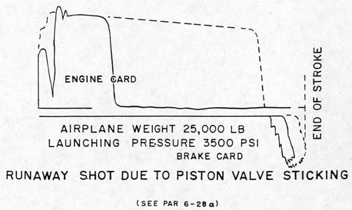
6-28. In a cold shot in which the crosshead starts to move, hesitates momentarily allowing the bridle to slacken and then proceeds normally, the bridle will either slip off the hooks or will part when rue load is applied again thus breaking the bridle and causing a runaway shot (see paragraph 6-29). The causes of this malfunction would be:
a. The piston valve sticking momentarily and then opening fully due to binding of the valve or an obstruction in the valve. See figure 7-5 for a typical indicator card. See paragraph 5-79 for correction procedure for disassembly.
6-29. RUNAWAY SHOT. A runaway shot, usually the result of a cold shot, is defined as a launching in which excessive speed of the catapult is developed. Runaway shots, if not controlled, will damage the engine. One of the chief causes of a runaway shot is a cold shot in which the catapult, having lost the drag of the plane's weight, builds up a speed greatly in excess of that normally obtained for the launching pressure and weight being used. A runaway shot will result in any cold shot where the crosshead resumes its forward motion after losing the connection to the he airplane. A runaway shot may also result from
an operator's error in setting up a launching pressure above the pressure ordered for weight of plane to be launched. Interruption of a runaway shot is provided by the runaway shot preventer as detailed in paragraph 3-66. Prevention of repetition of a runaway shot is accomplished by correction of the malfunction or error causing the runaway shot. The catapult shall be inspected thoroughly after a runaway shot where the end speed exceeds 105 knots. Carefully examine the retrieving cable, cable tensioner, tensioner equalizer cable, sockets, and terminals and all sheaves.
6-30. A runaway shot resulting from failure of a bridle which did not go slack first would indicate a faulty bridle or a faulty bridle installation. Bridles must be inspected thoroughly before each use.
6-31. SLOW SHOT. A slow shot is a launching (other than a cold shot) where the catapult end speed is below that normally obtained for the launching pressure and weight being used. This may result in the loss of the aircraft.
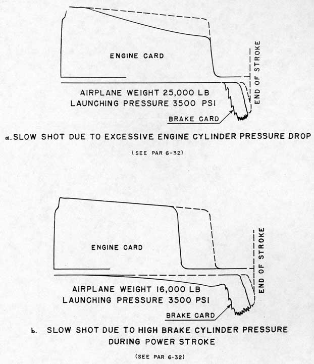
6-32. Where a full power run of the crosshead is obtained, the slow shot would be due to excessive engine cylinder pressure drop, to partial opening of the piston valve, or to excessive back pressure in the ????e cylinder. See Figure 7-6 for typical indicator cards. The normal brake stroke for given launching
conditions can be determined by referring to figures 7-1 and 7-8. Excessive engine cylinder pressure drop will result from the presence of appreciable amounts of fluid in the air flasks. A slow shot resulting from excessive pressure drop can also result from partial opening of the piston valve and choked fluid flow. This would probably be audible in the catapult compartment. A slow shot can also result from excessive back pressure in the brake cylinder. This could be the result of a partial closure of the bypass valve, either prematurely or by a misalignment. The alignment of the bypass valve is to be checked daily, see paragraph 5-63c 4. The bypass valve must be aligned as outlined in paragraph 5-63 before any launchings are made.
6-33. If the power run of the crosshead is shorter than normal, the slow shot is due to premature cutoff of launching pressure. Premature cutoff may be caused by a malfunction of the runaway shot preventer valve. If the operating piston spring fails to seat the operating piston in the closed position or if the operating piston binds in its chamber and fails to seat, the fluid from the RSP cylinder could flow past the operating piston to actuate the piston of the RSP valve and return the firing operating valve to "standby" thus cutting off the launching pressure. The position of the RSP indicator rod must be checked as provided in paragraph 3-66 to prevent this malfunction.
6-34. NORMAL AIRPLANE LAUNCHING. Difficulties are included here which do not materially affect the launching of the airplane.
6-35. If the "STANDBY" and "FINAL READY" lights do not go out and four-way solenoid valve and firing solenoid valve do not energize at the beginning of the stroke, either the X switch has failed in the closed position or the bridle tensioning relay is sticking in the energized position. If the difficulty is due to the relay sticking, the lights will usually go out at the brake stroke due to normal catapult vibration. Free relays as detailed in paragraph 5-9i. If the difficulty is due to failure of the X switch, the "STANDBY" and "FINAL READY" lights will go out at the end of the power stroke and the "STANDBY" lights will relight again and the tensioner solenoid will be energized several seconds after the retracting button is released. Replace the X switch to correct malfunction.
6-36. If the "FIRST READY" lights relight after retracting, both first ready relays are "hanging up" in the energized position. Free relays as detailed in paragraph 5-9i.
6-37. If the retrieving cables go slack during the power stroke, the cable tensioner is sluggish. Make
97
certain tensioner dome pressure is 800 psi. Sluggish tensioner action will be due to a sticking tensioner piston, sticking clapper valve, misalignment of tensioner tracks, or excessively tight packing. See Section V - Maintenance for correction procedures.
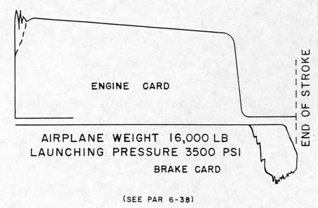
6-38. Excessive initial engine cylinder pressure as shown by the engine indicator card can be due to excessive wear or failure of the engine ram throttling plug. Figure 7-4 shows a typical indicator card for this condition. Operations shall be discontinued until the difficulty is corrected. In addition, in the fluid supply line to the firing operating valve there is an orifice which meters the flow of the fluid to the firing operating valve to control the rate of opening of the piston valve. If this orifice were accidentally removed or is not replaced following a maintenance operation, then its metering action being absent, excessive initial engine cylinder pressure would result.
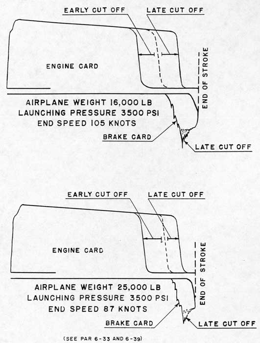
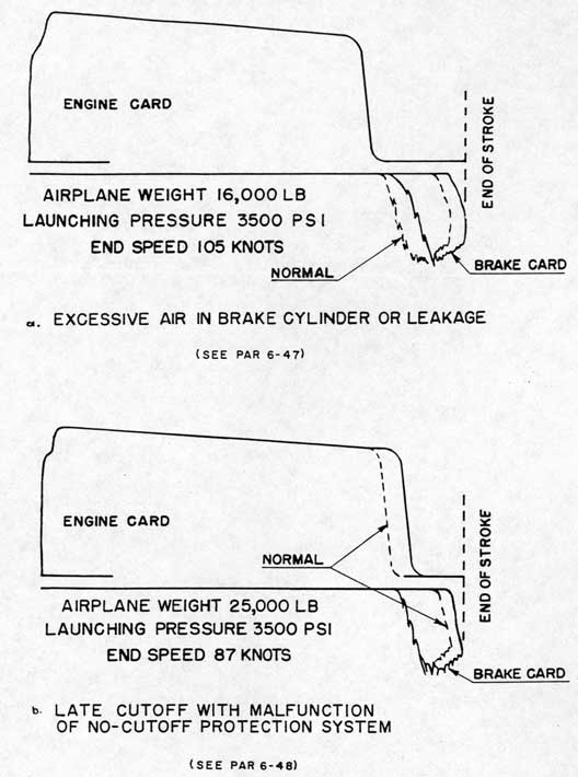
6-39. LATE CUTOFF. "Late cutoff" is that malfunction where the engine cylinder pressure is not reduced to zero until after the brake pressure rise begins. A comparison of engine and brake cylinder indicator cards will indicate this condition as shown by figure 7-7. This would include the condition where the pressure was not reduced until the end of the brake stroke. A late cutoff would be due to:
a. An obstruction in one of the following pipe lines: high pressure fluid line from firing operating valve to piston valve; low pressure fluid line from firing operating valve to return line to launching gravity tank. Check all lines for obstruction.
6-40. NO CUTOFF. "No cutoff" is that malfunction where the indicator cards show no engine pressure drop and an abnormally high brake pressure and stroke. The engine cylinder will remain under accumulator pressure and the crosshead will creep into the hydraulic stops. This condition will be due to non-operation of the firing operating valve due to failure of the mechanical cutoff or binding of the piston in the open position. The catapult shall be inspected carefully after a "no cutoff" shot. Inspect the retrieving cable, the cable tensioner, the tensioner equalizer cable, sockets and terminals, and all sheaves, especially the retrieving sheaves.
6-41. BRAKE STROKE.
6-42. GENERAL. Malfunctions are included here which would be observed during the brake stroke; that is, from the time the bypass valve is closed till the crosshead comes to rest. Also included are difficulties which are indicated by the brake cylinder pressure indicator cards.
6-43. EXCESSIVE TOW CABLE WHIP. This would be
due to the sluggish operation of the cable whip dampers. Make certain whip damper dome pressure is 800 psi. Sluggish whip damper action is due to binding of the piston in the cylinder, sticking clapper valve, or misalignment of whip damper tracks. Eliminate cause of sluggish action. See Section V - Maintenance for correction procedures.
6-44. ERRATIC REBOUND. After the brake stroke, the crosshead will normally rebound before stopping. If the crosshead "bounces" back and forth several times before coming to rest it is an indication that the elbow check valve is air bound. If the elbow check valve is not open after the shot, the air trapped in the engine cylinder must be vented to permit retraction. To eliminate this condition the piston valve must be vented thoroughly through the blowdown valve. When operating above 2500 psi it must be vented while pumping fluid between launchings.
6-45. EARLY BRAKE STROKE. Normally the catapult brake pressure starts to build up after a crosshead motion of 15 feet. If the indicator cards show the brake pressure build up starting before 15 feet of crosshead travel, the catapult must not be operated until the cause has been eliminated. An early brake stroke will reduce the total crosshead stroke and increase the brake pressure since the engine cylinder pressure is not cut off when an early brake stroke starts. The cause of an early brake stroke is an improper alignment of the bypass valve plug. For procedure to correct the misalignment see paragraph 5-63. This alignment must be checked daily as required by paragraph 5-8j.
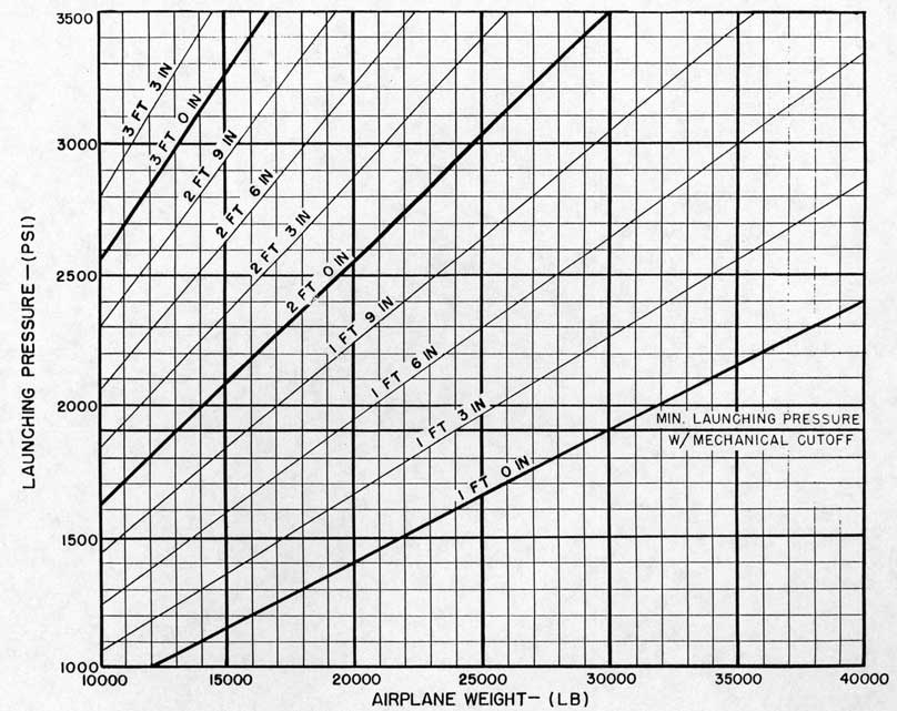
6-46. EXCESSIVE BRAKE PENETRATION OR PRESSURE. Brake penetrations normally depend upon aircraft weight and launching pressure. The normal brake stroke for a certain launching can be obtained from figure 7-8. The actual brake stroke can be determined from the brake pressure indicator card as shown by figure 7-1. A brake stroke obtained from a brake indicator card may normally vary by about three inches, plus or minus, from that shown in figure 7-8.
6-47. A brake indicator card similar to figure 7-9a, showing a delayed pressure rise and increased brake stroke, will indicate excessive entrained air in the brake cylinder or considerable leakage from the brake cylinder. Vent catapult thoroughly to prevent this malfunction. See paragraph 4-2y for venting procedure.
CAUTION
During a series of launchings, retraction shall not be made until the initial retracting accumulator pressure and fluid level have been recovered.
98
Check for brake cylinder leakage with crosshead in battery position by holding the retracting button down for several minutes. A rapid and continuous retracting accumulator pressure drop will indicate excessive leakage past the bypass valve plug or constant pressure valve spindle.
6-48. Indicator cards similar to those shown in figure 7-9b, will indicate late cutoff with no cutoff protection. For a late cutoff malfunction, see paragraph 6-39. Lack of no cutoff protection would be due either to air in the 4-inch line from the air trap cylinder to the constant pressure valve, due to the air trap cylinder piston being stuck in the battery position, or due to blocked clapper valve orifices. Make certain the 4-inch line is solidly full of fluid and that there is no air in the line. If necessary, provide additional vents. Observe the air trap cylinder plunger during a shot. If the plunger does not move out of sight when the catapult is fired, the air trap cylinder piston is stuck, see paragraph 5-83 for correction procedure, or the clapper valve orifices are blocked, see paragraph 5-85 for correction procedure.
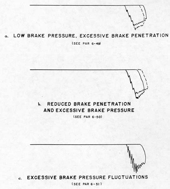
6-49. Excessive brake penetration due to low brake pressure will result in an indicator card similar to figure 7-10a. This malfunction may be due to a reduction of air pressure in the constant pressure valve dome. Check for leak by observing the dome pressure for 15 minutes. If there is a continuous pressure drop, locate air leak and eliminate. Excessive penetration due to low brake pressure may also be due to failure of the bypass valve to close thus allowing braking pressure to blow through to the retracting gravity tank. Failure of the bypass valve to close may be due to misalignment or a malfunction of the mechanical controls. The cause shall be traced and eliminated.
6-50. Reduced brake penetration and excessive brake pressure will be shown by an indicator card similar to figure 7-10b. Inspect catapult, especially the sheaves and retrieving system. This condition is due to either excessive air pressure in the constant pressure valve dome or pressure in the auxiliary dome of the constant pressure valve after normal cutoff. Excessive air pressure in the constant pressure valve dome would be caused by a leaking air charging valve or a faulty gage. Check the constant pressure valve dome pressure over a 15 minute period with the air charging valve closed and ship's high pressure air on. If pressure increases continuously, repair valve. If the air charging valve does not leak, difficulty is due to:
a. Trapped air in constant pressure valve auxiliary dome because of improper venting. Care must
be taken not to trap air in the 4-inch Line when filling with fluid. Do not pump into line with vents closed.
b. Slow pressure drop in auxiliary dome at cutoff. Check air trap cylinder for a binding piston or clapper valve. See paragraphs 5-83 and 5-85 for corrective procedures.
6-51. A brake pressure indicator card similar to that shown in figure 7-10c, showing excessive brake pressure fluctuations, will indicate a sticking constant pressure valve piston or spindle. Disassemble the constant pressure valve as detailed in paragraph 5-139 and eliminate cause of excessive friction.
6-52. RETRACTION.
6-53. GENERAL. Malfunctions are included here which would occur from the time the "RETRACT" button is depressed till the crosshead is in full battery position.
6-54. CATAPULT DOES NOT RETRACT.
a. If, when the "RETRACT" button is depressed, nothing happens, then:
1. Contact button is faulty.
2. Damping cylinder solenoid valve (RVS) is binding or solenoid is burned out.
3. Firing relay is binding in "FIRE" position ("FIRE" light remains on).
b. If when the "RETRACT" pushbutton is depressed, the damping cylinder solenoid valve is energized but the damping cylinder does not move, then:
1. The damping cylinder is binding or
2. The bypass valve is binding.
c. If mechanical linkage is actuated to trip RV2 switch, but retracting solenoid valve (RS) is not energized, check for electrical malfunction of RV2 switch or of solenoid.
d. If retracting solenoid valve is energized but retracting operating valve is not actuated, check for binding of solenoid valve or retracting operating valve.
e. If retracting operating valve is actuated but catapult does not retract, check for binding of retracting valve as detailed in paragraph 5-119.
6-55. SLOW START OF RETRACTION. After the "RETRACT" button is depressed, 2 to 3 seconds will normally elapse before the crosshead starts to move. If the elapsed time is more than five seconds, the cause of the delay shall be determined and eliminated. If this condition occurs when retraction is started with the crosshead in the brake stroke position (bypass valve closed), the difficulty is due to excessive mechanical friction in the retracting valve. Disassemble the retracting valve at earliest opportunity and eliminate cause of malfunction.
99
6-56. If excessive time for starting retraction is observed only when the crosshead is out of the brake stroke position (bypass valve open), the source of difficulty can be determined by observing motion of the mechanical linkage crank when the "RETRACT" button is depressed. Slow crank motion throughout the entire stroke will indicate excessive friction in the mechanical linkage, bypass valve, or damping cylinder. If mechanical linkage crank drops normally at beginning of stroke and then "creeps" to final position, the bypass valve damping cylinder is at fault. The groove in the damping cylinder piston is not lined up with "B" as shown on NAFACT Drawing No. 24-4503. See paragraph 5-143 for procedure to line up the groove.
6-57. SLOW RETRACTION. Slow rate of retraction may be due to a failure of the engine cylinder to vent to the launching gravity tank due to sticking of the elbow check valve. A sticking of the valve may be determined by observing the position of the valve rod. To correct sticking or other failure to open see paragraph 5-91 for procedure.
6-58. A slow rate of retraction may also be the result of escape of retracting pressure through the constant pressure valve due to a failure of the constant pressure valve lower spindle such as cracking of the spindle cap or failure of the spindle seat. To establish this cause for slow retraction put the catapult on "retract" with crosshead in battery position. If the pressure drops excessively in the retracting accumulator it is an indication that the constant pressure valve is not seating to contain the retracting pressure. Procedure for correction of the failure will be found in paragraph 5-139.
6-59. If slow retraction is noted accompanied by excessive penetration of the brake as shown on the indicator card it is an indication that the bypass
valve is leaking excessively. The catapult shall be secured and the bypass valve spool removed for inspection.
6-60. YELLOW LIGHT DOES NOT COME ON. If the "CROSSHEAD FULLY RETRACTED" light does not come on with the retracting button depressed after the shuttle has stopped, check position of crosshead. If crosshead is in battery position, then the catapult fully retracted switch (CB) is at fault. If crosshead cannot be returned to battery position, check for obstruction at crosshead or shuttle tracks. If there is no obstruction, either the bridle tensioner jacks are binding or the engine ram plug is hanging up on the engine cylinder elbow orifice.
6-61. LOSS OF RETRACTING ACCUMULATOR PRESSURE. If the retracting accumulator pressure drops more than 40 to 50 psi when the "RETRACT" button is released, the bypass valve is opening before the retracting valve closes. If the retracting valve actuating time is normal, then check for installation of the throttling plug in the atmosphere port of "RVS" solenoid valve.
6-62. If the retracting accumulator charge blows through to the retracting gravity tank when the retracting button is released, the retracting valve stem has failed. Disassemble retracting valve and repair. See paragraph 5-119 for disassembly procedure.
6-63. BYPASS VALVE DOES NOT OPEN. If the bypass valve does not open when the retracting button is released, check for binding of the mechanical linkage. damping cylinder, or bypass valve. Determine source of difficulty by separating the bypass valve plug and damping cylinder piston from the mechanical linkage. If all parts are free when separated, check for binding at the mechanical linkage crank or for misalignment between the damping cylinder and mechanical linkage.
100
SECTION VII PRESSURE INDICATOR CARDS
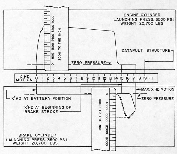
7.1. GENERAL. Two Bacharach pressure indicators are installed on all H8 catapults, one to record engine cylinder pressures and the other to record brake cylinder pressures. Instructions for operation and maintenance of these indicators are furnished by the manufacturer. A pressure indicator is a precision instrument and must be handled with care. The indicators shall be calibrated at least once a month with a dead weight pressure gage tester.
7-2. Scales are furnished with the indicators to measure the pressure indicated by the trace. The scale marked "2000 TO THE INCH" must be used with engine cylinder indicator cards and the one marked "8000 TO THE INCH" with the brake cylinder indicator cards. The cylinder pressure in pounds per square inch (psi) is obtained by measuring the vertical distance between the zero pressure line and the trace are shown in figure 7-1. The crosshead position corresponding to any cylinder pressure can be obtained by measuring the horizontal distance from the beginning of the trace to the point in question. For this purpose a "CROSSHEAD MOTION" scale similar to that shown in figure 7-1 shall be made for each catapult. The distance between the foot marks on the scale shown is 0.23 inches. This calibration must be checked on each catapult by marking a straight line trace on a brake cylinder indicator card while moving the crosshead about 10 feet from battery position. The length of the trace in inches divided by the actual crosshead motion in feet will give the proper calibration to be used for the catapult in question.
7-3. Considerable information can be obtained from the indicator cards. For example, figure 7-1 shows that the maximum engine cylinder pressure was 3400 psi and it occurred when the crosshead had moved about one foot. The brake cylinder braking pressure starts to build up after a crosshead motion of 15 feet the maximum brake pressure was 8100 psi which is the "mean" or average of the fluctuation taken at the maximum pressure point and occurred at a crosshead
motion of about 16-1/2 feet; the maximum crosshead motion is about 17-1/2 feet. Subtracting the crosshead power stroke of 15 feet indicates a brake stroke of 2-1/2 feet.
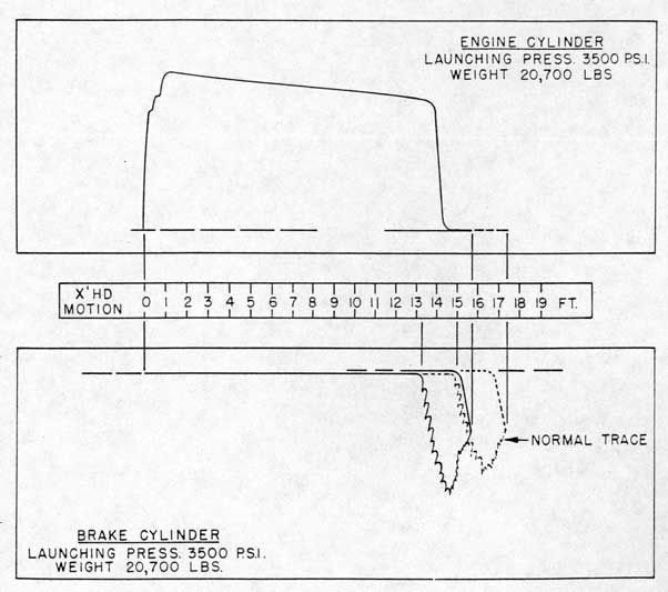
7-4. Variation in launching conditions and certain catapult malfunctions can be determined by a careful study of the pressure indicator cards. This section includes samples of indicator cards resulting from various catapult malfunctions. Figure 7-2 shows a sample of indicator cards obtained for an early brake stroke. A description of this malfunction will be found in paragraph 6-45. As indicated by figure 7-2, the brake pressure started to build up at about 13-1/4 feet instead of 15 feet and the total crosshead stroke was reduced accordingly by 1-3/4 feet. In addition, the brake pressure was increased since the engine cylinder pressure had not been cut off when the early brake stroke started. A catapult must not be operated, when this malfunction occurs, until the cause has been eliminated. An early brake stroke is caused by misalignment of the bypass valve plug. The proper alignment of the bypass valve plug is described in paragraph 5-62.
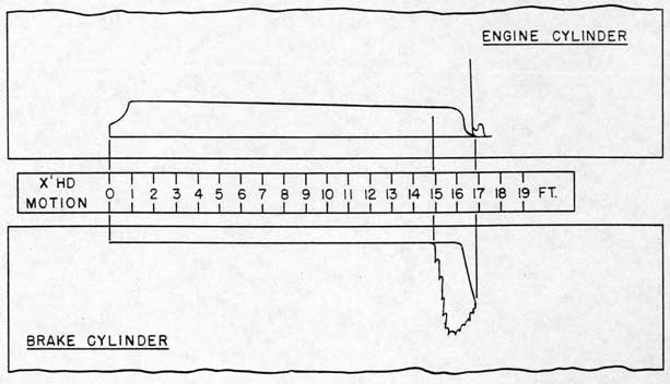
7-5. Figure 7-3 shows the type of indicator card that should be obtained for "no load" shots using a 2000 psi per inch spring. The engine cylinder pressure cutoff is somewhat late with a possible slight increase in brake pressure. The degree of lateness may vary slightly for different catapults. The engine cylinder pressure will usually "peak" during rebound as a result of the elbow check valve closing momentarily as indicated by figure 7-3.
7-6. The remainder of the figures depict typical indicator cards for the malfunctions described in Section VI. The correlation between the cards add the malfunction will be found in Section VI under the applicable malfunction. See paragraph 6-28 and following.
101
USE OF SCALES TO READ PRESSURE INDICATOR CARDS
Figure 7-1. Normal Indicator Cards
102
Figure 7-2. Indicator Cards Showing Early Brake Stroke
Figure 7-7. Indicator Cards - Early and Late Cutoff
107
Figure 7-8. Brake Stroke - Various Launching Conditions
108
Figure 7-9. Indicator Cards - Brake Malfunctions
109
Figure 7-10. Indicator Cards - Brake Malfunctions
110
APPENDIX I CHECK-OFF LIST TYPE H, MARK 8 CATAPULT
A-1 RESPONSIBILITY.
A-2 Catapult officers are required to sign checkoff list before each launching operation or when the catapult is not used for a period of one hour or more during a series of launchings. The signature of the catapult officer is a certification that he has checked all items of the list by personal observation and has found the catapult ready for firing. Discrepancies noted when checking items listed must be fully rectified prior to firing the catapult.
A-3 UPKEEP AND MAINTENANCE.
a. Maintenance Schedules Completed.
__ Wipe down.
__ Lubricate catapult.
__ Maintenance and lubrication schedules up to date: Weekly, 100 launchings, Semimonthly, Monthly, ????00 launchings, Quarterly and Semiannual.
A-4 LAUNCHING PREPARATION.
a. General.
__ Electric power available for operation of pumps and signal system.
__ Low pressure air supply at proper pressure.
__ Constant pressure valve spindle in proper position.
__ Bypass valve rotor in proper alignment.
__ Proper amount of fluid in launching and retracting gravity tanks.
__ All materials not part of catapult (rags, wrenches, etc.) removed from catapult.
b. Valves.
__ All drain valves and vent valves -closed.
__ Shutoff valves in pump suction, discharged, and return lines - open.
__ Shutoff valve to low and high pressure air supplies - open.
__ Launching and retracting accumulator blowdown valves - closed.
__ All air blowoff valves - closed.
__ Air shutoff valves on accumulators - open.
__ Liquid level gage shutoff valves - open.
__ Gate valve in return line to gravity tank - open.
__ Shutoff valve to 4 way valve - open.
__ Pump pressure regulator shutoff valves - open.
__ Air charging valves to accumulators, whip
dampers, tensioner, and constant pressure valve - closed.
c. Cable Tensioner.
__ Daily check of fluid level completed (fluid at level plug with ram fully in, using glycerine-water-borax mixture in accordance with paragraph 5-162).
__ Dome charged with air to 800 + 25 - 10 psi.
d. Cable Whip Dampers.
__ Daily check of fluid levels completed (fluid at level plugs with rams full out, using glycerine-water-borax mixture in accordance with paragraph 5-162).
e. Constant Pressure Valve.
__ Lower dome charged with air to 260 psi (condensate vented from air supply lines before charging).
f. Runaway Shot Preventer.
__ Oil level in reservoir at red line on level gage with crosshead in battery position.
__ RSP Valve spring at correct setting.
__ RSP switch clears indicator rod by 0.010 inch.
__ Extension rod lubricated.
__ Reservoir charged with air to 15 psi with crosshead in battery position.
g. Accumulator Charges.
__ Proper initial air charge in launching accumulator for pressure range to be used.
__ Fluid level at 9 inches in center gage or above. _ Proper retracting accumulator air charge (850 psi at fluid level of 5 inches in level gage ).
h. Deck Preparation.
__ Track covers or protectors removed.
__ Shuttle at proper position (aft end of shuttle 20 inches from aft end of track).
__ Proper and sufficient launching bridles or pendants on hand and inspected.
__ Proper size and quantity of holdback rings or bars.
__ Proper holdback and release equipment.
__ Track clear and clean, slipper oilers filled.
__ Daily check of bridle tensioning force completed.
i. Functional Checks.
__ Check operation of each pump.
__ Daily check of signal system (supply valve closed, securing stem in, and lock on firing operating valve for this check. See paragraph 5-8k).
__ Check operation of mechanical controls for freedom of operation during signal system check.
j. Venting.
__ Main engine cylinder.
__ Piston valve (vented while pumping fluid).
111
__ Air trap cylinder, 4 inch line and constant pressure valve auxiliary dome.
__ Hydraulic stops.
__ Elbow check valve.
__ Cable tensioner cylinder.
__ RSP cylinder and RSP valve.
__ Bridle tensioner jacks.
__ Brake cylinder (special venting required).
k. Venting Between Launchings.
__ Lock on firing operating valve.
__ Piston valve (vented while pumping fluid). Brake cylinder.
__ Bridle tensioner jacks.
__ Main engine cylinder.
____
________________
Date
Catapult Captain
l. Final Prelaunching Check.
__ Bridle tensioner pressure at required value.
__ Launching accumulator pressure at value ordered by catapult officer.
__ Speedometer switch on.
__ Supply valve to firing operating valve opened.
__ Piston valve securing stem out.
__ Lock removed from firing operation valve.
I certify that this catapult has been visually checked by me and that all maintenance, operating, and safety instructions have been carried out to prevent damage to machinery or injury to personnel.
____
________________
Date
Catapult Officer
A-5 SECURING AFTER LAUNCHINGS.
__ Lock assembly on firing operating valve and padlock locked.
__ Supply valve to firing operating valve closed. Piston valve securing stem in.
__ Retracting accumulator fluid level at 5 inches in gage.
__ Launching accumulator fluid level at 9 inches in center gage.
__ All pumps turned off.
__ Speedometer turned off.
__ Signal system power supply turned off.
__ Check cables for broken wires, sockets for slippage.
__ Check shuttle slippers for wear.
__ Catapult vented, all vent valves and drain valves closed. All blowdown, blowoff, and charging valves closed.
__ Deck equipment stowed.
__ Track and shuttle covers installed.
__ Wipe down, inspect for leakage, worn parts, excessive clearances.
I certify that this catapult has been properly secured.