3-2. The function of the launching system is to contain, control, and direct the launching accumulator pressure so as to transmit the power of the engine to the shuttle to launch the airplane. The launching system consists of the following.
a. The Launching Accumulator and Manifold
b. The Piston Valve and the Elbow Check Valve
c. The Four-Way Valve
d. The Firing Operating Valve
e. The Cylinder and Ram
f. The Crosshead
g. The Fixed Sheaves
h. The Bridle Tensioner
i. The Cable Whip Dampers
j. The Cable Equalizer
k. The Cable Tensioner
l. The Runaway Shot Preventer
m. The Shuttle
n. The Cables
o. The Holdback and Release Units
p. The Launching Bridle.
3-3. LAUNCHING ACCUMULATOR AND MANIFOLD.
3-4. The launching accumulator receives and stores the fluid from the pumps and delivers it, at launching pressure, to the piston valve via the manifold.
3-5. The launching accumulator is a high-pressure, cylindrical, steel vessel which is flanged at each end. A cap on top of the accumulator contains the air charging line and a relief valve. Around the cap are four flanges for the piping of the four air flasks. A flange on the bottom of the accumulator connects the manifold. The manifold runs from the bottom of the accumulator to the piston valve. The manifold has seven ports, one for delivery from each of the seven launching pumps.
3-6. The launching fluid is pumped from the sump tanks into the launching accumulator via the manifold. The accumulator contains an initial charge of compressed air and the piping of the accumulator and its air flasks is so interconnected that the compressed air can pass freely from one vessel to another, thus maintaining uniform pressure on the fluid. The hydraulic
output of the pumps further compresses the air charge in the accumulator to the required launching pressure. The flow of the high-pressure fluid from the launching accumulator to the main engine cylinder, via the manifold, is controlled by the piston valve.
3-7. PISTON VALVE.
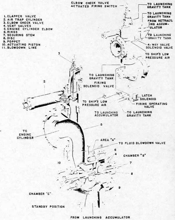
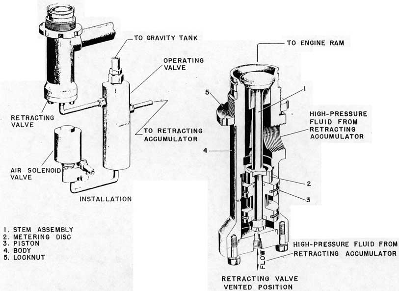
3-8. The piston valve, figure 3-1, controls the flow of the high-pressure fluid from the launching accumulator to the main engine cylinder.
3-9. The piston valve is a pilot-operated, differential piston valve with two ports; one from the launching accumulator through the manifold and the other to the main engine cylinder elbow (5). The poppet (9) of the valve, a welded assembly provided with rings (6), slides within the valve body to provide the sealing action of the valve. The shaft of the poppet mounts the actuating piston (10). The actuating piston is operated in its cylinder to slide the poppet to the open or closed position. In the large head at the opposite end from the actuating piston cylinder is the securing stem (7). The large head is provided with vents (4). The fluid blowdown line (11) is connected to the area surrounding the outer surface of the poppet to aid in venting collections of air.
3-10. When the catapult is in standby position during operations, accumulator pressure acts on the differential annular area "A" of the poppet holding it closed; chamber "B" is vented to the launching gravity tank and the manually operated securing stem is in the "fully out" position.
CAUTION
The piston valve securing stem must be maintained in the "fully out" position during catapulting operations. The securing stem will extend 9 3/4- plus or minus 1/16-inches beyond the valve cover.
3-11. The operating sequence for the piston valve is as follows: When the "FIRE" button is pressed, a solenoid valve is energized and air actuates the four-way valve allowing fluid from the retracting accumulator to close the elbow check valve. The rod at the top of the elbow check valve contacts the
13
Figure 3-1. Piston Valve, Elbow, and Elbow Check Valve
14
auxiliary firing switch, the firing solenoid valve opens, and air actuates the firing operating valve thus allowing fluid from the launching accumulator to enter the actuating piston cylinder (chamber "C") of the piston valve. The area of the face of piston "D" is slightly larger than the differential area "A" of the poppet. The force exerted at face "D" is therefore greater than that against "A", consequently the poppet is forced off its seat by the actuating piston "D". An orifice in the supply line at the firing operating valve regulates the speed of the poppet. A throttling skirt on the poppet provides for gradual pressure increase in the elbow. The main port from the manifold is then fully opened, allowing fluid at accumulator pressure to enter the elbow and engine cylinder forcing the ram forward.
3-12. Near the end of the launching stroke the firing operating valve is mechanically returned to standby cutting off accumulator pressure to chamber "C" and venting it to the launching gravity tank. The piston valve now returns to standby position due to the force of the launching pressure acting on the inner end of the actuating piston until the pressure drop in the elbow allows the unbalanced annular area "A" of the poppet to act, closing the piston valve and sealing the manifold port.
3-13. When securing the catapult, the securing stem is turned to the "fully in" position to seat the disc (8) against the poppet. Pressure developed through fluid leakage by the rings is confined in chamber "B" and-prevents further leakage past the rings. In preparing the piston valve for catapulting operations, chamber "B" must be vented before attempting to turn the securing stem.
3-14. FOUR-WAY VALVE.
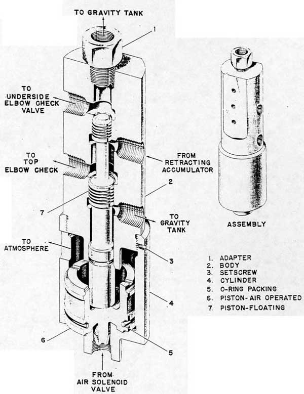
3-15. The four-way valve, figure 3-2, controls the opening and closing of the elbow check valve.
3-16. The four-way valve contains two pistons: a differential floating piston (7) and an air operated piston (6) sealed by an O-ring (5). The body (2) of the valve threads into the cylinder (4) and is secured by a setscrew (3). An adapter (1) is provided to make the gravity tank connection.
3-17. When the "FIRE" button is pressed, the four-way valve solenoid valve opens, actuating the air operated piston which overcomes force from the hydraulic pressure on the differential floating piston and moves it up, allowing the hydraulic fluid from the retracting accumulator to enter the underside of the elbow check valve, forcing it closed. When the four-way valve solenoid valve is de-energized, the air operated piston is vented. Force unbalance in the
four-way valve returns the floating piston to standby position and admits retracting accumulator pressure to the top of the elbow check valve. Since launching pressure is greater than retracting accumulator pressure the elbow check valve will not close until launching is completed and cutoff is attained.
3-18. FIRING OPERATING VALVE.
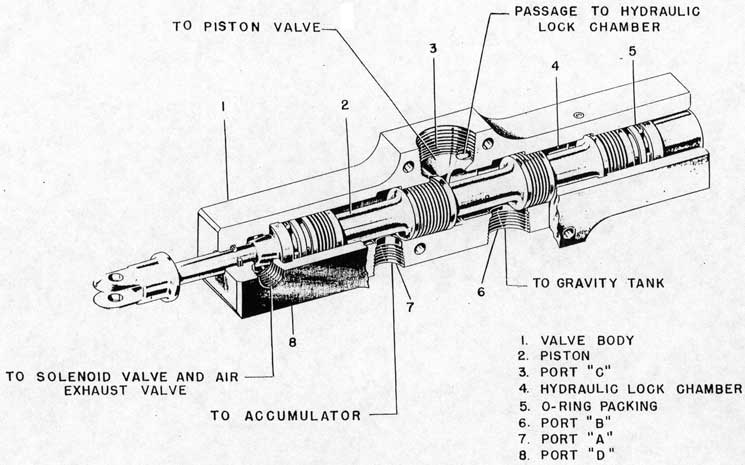
3-19. The firing operating valve, figures 3-1 and 3-3, controls the opening and closing of the piston valve.
3-20. The firing operating valve is an air-actuated, spool type valve with four ports. Port "A" (7) is open to the launching accumulator when the supply valve is opened. Port "C" (3) vents piston valve actuating piston to gravity tank except during firing when it is opened to port "A". Port "B" (6) is open to the launching gravity tank. Port "D" (8) is open to the firing operating valve solenoid valve. The hydraulic lock chamber (4) is open to port "C". The hollow, stepped piston (2) is sealed against leakage and loss of pressure by means of O-rings (5). A vent plug is provided on top of the valve body (1). A differential piston at the latch solenoid end provides a hydraulic lock to keep the valve in the fired position. The piston extends through the other end of the valve for connection to the mechanical cutoff and for securing the catapult by a padlock assembly.
3-21. The operating sequence for the firing operating valve is as follows: at standby, with the padlock assembly removed from the piston, launching pressure from the launching accumulator enters port "A". The lock pin of the solenoid lock assembly being down past the end of the piston serves as a check against piston movement. Port "B" is vented to the launching gravity tank and any leakage past the spools of the piston will flow out to the gravity tank. Port "C" is open to gravity tank. Port "D" is open to the firing solenoid valve but is not pressurized since the firing solenoid valve has not yet been actuated.
3-22. When the "FINAL READY" signal (red light) is given, the latch solenoid is energized lifting the lock pin. The firing operating valve is now unlocked and is in position to be fired.
3-23. When the firing solenoid valve is energized, low-pressure air enters port "D" of the firing operating valve. This low-pressure air moves the piston to the fired position. When the piston moves in to fired position port "C" is open to port "A" and launching accumulator pressure flows to the actuating piston chamber of the piston valve to open the piston valve and admit launching pressure to the cylinder and ram. Pressure in port "C" passes to the hydraulic
15
Figure 3-2. Four-Way Valve
16
Figure 3-3. Firing Operating Valve
17
lock chamber to keep the valve in the fired position independent of the electrical and low-pressure air supplies.
3-24. When the firing operating valve piston moves to the fired position it also lifts the roller of the mechanical cutoff in the way of the crosshead cam.
3-25. When the crosshead movement trips the crosshead switch the firing solenoid valve is de-energized and the firing solenoid valve vents air from the hydraulically locked firing operating valve. The lock pin solenoid is also de-energized allowing the pin to rest upon the firing operating valve piston.
3-26. Near the end of the power stroke the crosshead cam depresses the mechanical cutoff roller assembly, which - through the mechanical linkage to the firing operating valve piston - overcomes the hydraulic lock on the firing operating valve and returns it to standby. The pin of the lock pin solenoid drops down into position to prevent refiring. The firing operating valve may also be returned to standby by the action of the runaway shot preventer as detailed in paragraph 3-66.
3-27. ELBOW CHECK VALVE.
3-28. The elbow check valve, figure 3-1, prevents the flow of high-pressure launching fluid from the main engine cylinder elbow to the launching gravity tank during the power stroke and permits and meters the flow of low-pressure fluid from the launching gravity tank into the main engine cylinder elbow at any position other than firing position. It further functions to actuate the auxiliary firing switch which energizes the firing solenoid valve.
3-29. The elbow check valve (3) is a pilot operated double disc poppet valve. The poppet at the lower port of the valve seals the engine cylinder elbow (5) from the upper port of the valve which is open to the launching gravity tank. The valve position is controlled by an actuating cylinder at the upper end of the valve stem which is operated by the four-way valve. The upper chamber is pressurized to keep the valve open except for firing. For launching, the upper chamber is vented and the lower chamber is pressurized thus closing the valve and actuating the auxiliary firing switch. The stem of the valve moves upward to close by seating its double disc against the lower port. The opposite end of the stem is provided with an extension rod to actuate the auxiliary firing switch.
3-30. At standby position the elbow check valve is held open by retracting accumulator pressure from the four-way valve. The lower chamber is vented back through the four-way valve and fluid from the launching
gravity tank flows down through the lower chamber to fill the main engine cylinder and elbow. At the time the "FIRE" button is pressed the four-way valve is changed in position to vent the upper chamber of the elbow check valve and pressurize the lower chamber thus closing the valve and preventing launching pressure from escaping into the launching gravity tank. The elbow check valve is held closed by the four-way valve only during the initial portion of the launching stroke. It is held closed for the remainder of the stroke by the pressure of the launching fluid in the main engine cylinder elbow.
3-31. The crosshead's initial movement vents the four-way valve thus removing the retracting accumulator pressure from the lower chamber of the elbow check valve and applying the same pressure to the upper chamber. This will open the elbow check valve when the force from the launching pressure in the engine cylinder drops below the force from the retracting pressure. The elbow check valve opens at the drop of pressure to permit filling the engine cylinder during the brake stroke, venting of entrapped fluid during rebound, and to allow the crosshead to be retracted.
3-32. An air trap cylinder (2) and a clapper valve are installed between the engine cylinder elbow and the elbow check valve. The purpose and the function of these units are given in paragraphs 3-84 and 3-87.
3-33. CYLINDER AND RAM.
3-34. The ram, sliding within the fixed main engine cylinder and attached to the crosshead, transmits the engine forces to the crosshead during the launching and retracting cycles.
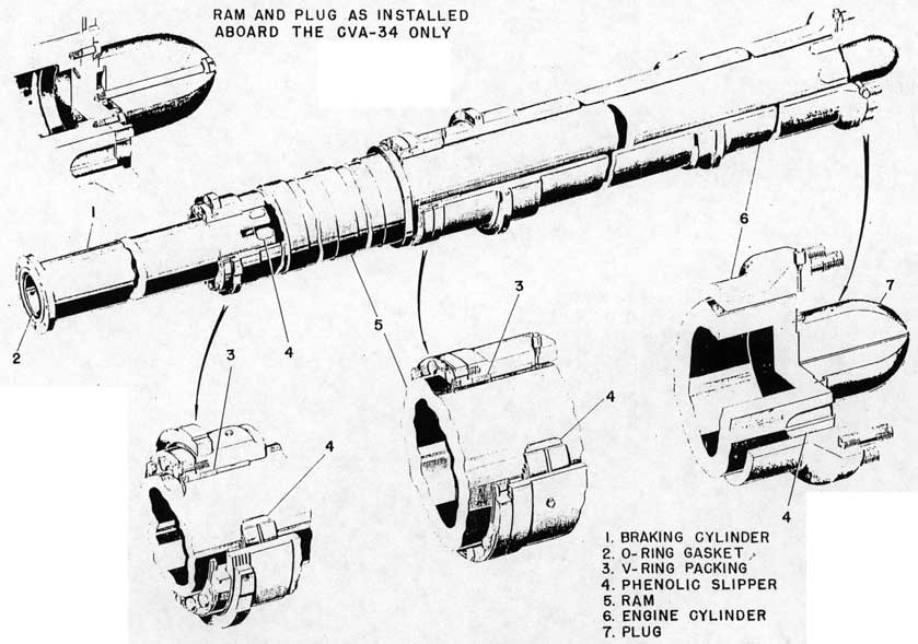
3-35. The cylinder and ram assembly, figure 3-4, consists of three concentric, steel cylinders. The engine cylinder (6) is supported by one end of the engine structure, the second cylinder, or ram (5), slides within the engine cylinder and over the third, or braking cylinder (1), fixed to the other end of the engine structure. The launching end of the main engine cylinder mounts an elbow leading up to the elbow check valve and down to the piston valve; the other end of the main engine cylinder is open to allow the ram to slide axially during the launching and retracting strokes. The ram end is sealed from leakage of launching fluid by means of V-type packing rings (3). The ram is a hollow cylinder which is closed and sealed at one end; the other end is open permitting the ram to slide over the braking cylinder. This latter end is sealed from leakage of retracting fluid by means of V-ring type packing rings which are positioned by a retainer bolted to the ram.
18
Figure 3-4. Cylinder and Ram
19
3-36. A metering plug (7) is incorporated as part of the ram. This plug extends into the engine cylinder elbow opening (with the ram at battery) to provide a gradual increase in pressure applied to the ram during launching and to act as a throttle at the end of the retracting stroke to stop the motion of the system without impact.
3-37. The braking cylinder is a hollow cylinder open at both ends. The end sliding within the ram is fitted with phenolic slippers (4); the opposite end (flanged) is bolted to a spacer which is bolted to the body of the bypass valve. The flange is sealed against leakage by an O-ring gasket (2).
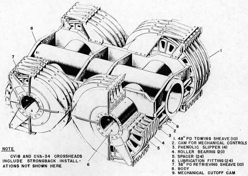
3-38. CROSSHEAD.
3-39. The crosshead, figure 3-5, transmits the forces from the ram to the towing and retrieving cables through the nests of sheaves around which these cables are reeved. The crosshead consists of a welded body (8) with four hollow shafts cantilevering outboard. Each shaft supports a sheave nest containing five sheaves furnished with roller bearings (4). Two nests at the towing end are equipped with 48-inch P.D. sheaves (1); the two retrieving nests (7) are 38-inch P.D. sheaves. Spacers (5) are provided for separating sheaves and for providing a passageway for the lubricant to the sheave bearings. Lubrication fittings (6) are provided on each spacer. The crosshead attaches to the ram and is supported by, and slides on, fixed tracks. Phenolic slippers (3) are used for the sliding bearings. Replaceable, split aluminum ferrules mounted on the crosshead and the fixed sheave housings are used to help guide the run of the towing and retrieving cables. A cutoff cam (9) is provided, bolted to the underside of the crosshead. This cam actuates the mechanical cutoff to return the firing operating valve to standby. Another cam (2), the crosshead cam, later actuates the mechanical controls to close the bypass valve and initiate the braking stroke.
3-40. FIXED SHEAVES.
3-41. Two nests of fixed towing sheaves and two nests of fixed retrieving sheaves, each mounted on shafts attached to the ship's structure, align with the respective nests of towing and retrieving sheaves on the crosshead. The sheave bearings have lubrication fittings installed within the hollow shafts.
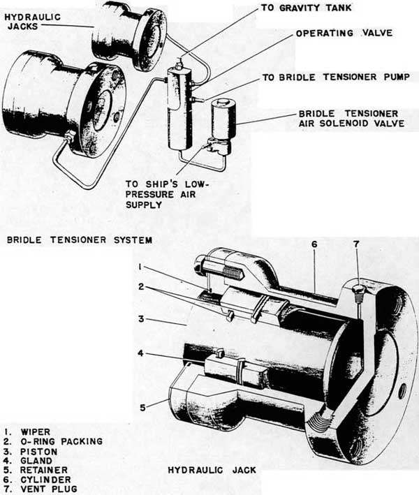
3-42. BRIDLE TENSIONER.
3-43. The bridle tensioner, figure 3-6, places an initial tension on the towing bridle. The tensioner consists of two hydraulic jacks mounted on the ship's structure, adjacent to the towing end of the crosshead. The jacks are of the plunger type and are
designed to force the crosshead away from its battery position thus moving the shuttle on deck forward and tensioning the towing bridle. The jacks consist of a cylinder (6) with a vent plug (7) and a gland (4). The gland seals the piston (3) by means of O-ring packings (2). The piston is furnished with a wiper (1) held against the gland by the retainer (5). The stroke of the jack is designed for 3 inches of travel. As the H8 catapult has a 10:1 reeving ratio, the maximum stroke of the tensioner will impart 30 inches of movement to the shuttle. The control for the operation of the bridle tensioner is located on the deck edge control panel.
3-44. In addition to the hydraulic jacks, the bridle tensioner system comprises a pump and motor unit; an air solenoid valve; a gage; and an operating valve. The pump is started from a pushbutton station located on the firing control panel and runs continuously throughout catapulting operations. The pump is fed from the sump tank and discharges fluid to the bridle tensioner operating valve. The bridle tensioner pressure must be determined individually for each catapult.
3-45. Tensioning of the towing bridle is accomplished as follows. The "BRIDLE TENSION" momentary contact pushbutton is depressed, actuating the air solenoid valve which controls the operating valve, directing pump discharge pressure to the pistons in the jacks. The pistons are forced outward and push the crosshead away from its battery position. The pistons are returned to their fully retracted position by retraction of the crosshead, after each launching. The pistons do not bottom at the end of retraction.
3-46. CABLE WHIP DAMPERS.
3-47. The function of the cable whip dampers, figure 3-7, is to take up the momentary slack in the towing cables which occurs when the ram is arrested during the braking stroke. This slack results from stretching of the retrieving cables during braking and, unless compensated for, results in a whip or slap of the towing cables. The dampers consist of two hydraulic cylinder, ram devices sliding on liners (12) in fixed tracks. Each cylinder (9) is connected through a clapper valve (8) to a dome (5) in which an air mass under pressure is trapped above enough liquid to permit the ram to completely enter the cylinder without entrance of air. The ram (10) connects to its sliding crosshead (1) to which the anchor end of the towing cable is attached. The end of the damper cylinder is connected to the equalizing cable around the shuttle positioner by means of a threaded coupling (11). A drain plug (3) is provided and the ram is packed at each end with V-ring packings (4). A gland (2) positions the V-ring packing of the crosshead end of the
20
Figure 3-5. Crosshead
21
Figure 3-6. Bridle Tensioner
22
Figure 3-7. Cable Whip Damper
23
ram to seal against possible leakage.
3-48. At the instant whipping of cable occurs, the towing cable slack is taken up by the ram moving into the cylinder. Sudden withdrawal is prevented by automatic closing of the clapper valve in which orifice holes are provided to prevent excessive pressures and to permit outward ram motion after whipping has been taken up.
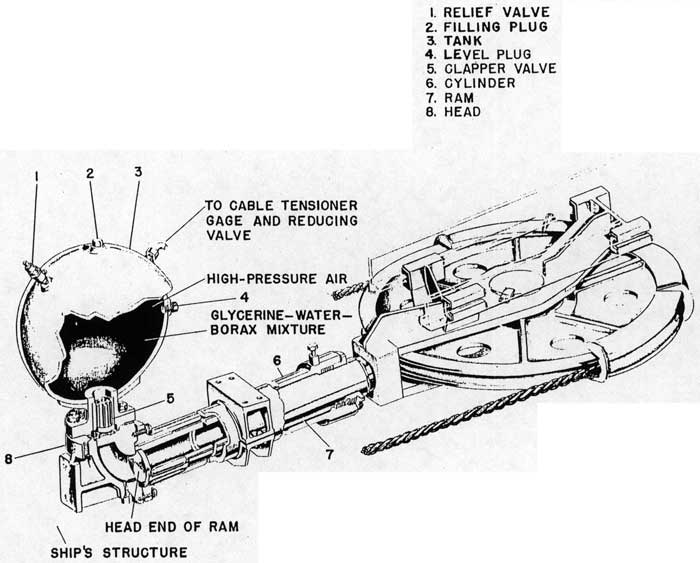
3-49. The cable whip damper is filled through the filling plug (6) to the level of its level plug (7) with the ram extended. A mixture of 80 percent glycerine and 20 percent distilled water plus sodium borate is used. Air pressure in the dome is maintained at 800 pounds per square inch as shown on the cable whip damper gage mounted on the firing control panel. A vent is provided at this gage for releasing air pressure. A relief valve is provided in the air line to the dome to guard against excessive pressure.
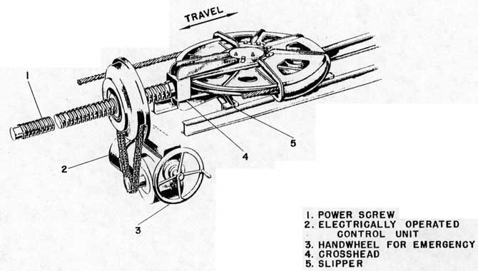
3-50. CABLE EQUALIZER.
3-51. The cable equalizer, figure 3-8, provides the means of permitting self-equalization of tension in the towing cables and serves as a shuttle positioner. The crosshead (4) is moved on slippers (5) by an electrically driven power screw (1); or, in an emergency, by a manually operated handwheel (3) and carries a sheave around which the equalizer cable is looped. This cable is attached to the two whip dampers. The towing cables are thus anchored, while at the same time being permitted to pass through from side to side as necessary to maintain equal tension. By moving the entire equalizer crosshead forward compensation for towing cable stretch is obtained and the shuttle can be relocated to its proper position as occasionally required.
3-52. A two-button, "FORWARD-REVERSE", momentary contact pushbutton station mounted on the flight deck - adjacent to the deck edge control box - provides a means for positioning the shuttle through the control unit (2). Holding the "FORWARD" button depressed causes the unit to operate to move the equalizer crosshead toward the piston valve, pulling on the towing cables, and thereby moving the shuttle forward. Holding the "REVERSE" pushbutton depressed causes the unit to operate to move the equalizer crosshead toward the fixed sheaves, thereby paying out on the towing cables. Slack thus put into the towing system is taken out by the cable tensioner with resultant aft motion of the shuttle. When using the "REVERSE" pushbutton, the motion of the cable tensioner may pull the crosshead out. Holding the "RETRACT" pushbutton down at the same time will prevent this motion of the cable tensioner from pulling out the crosshead.
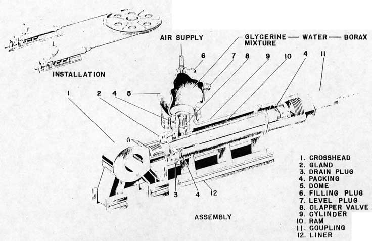
3-53. CABLE TENSIONER.
3-54. The function of the table tensioner, figure 3-9, is to eliminate slack in the cable system during towing and to provide an elastic anchorage for the retrieving cable during braking. The tensioner consists essentially of a ram-cylinder-tank assembly. The tensioner cylinder (6) is anchored to the ship's structure and is connected, through a clapper valve (5) above the head (8), to a dome in which an air mass is trapped above enough liquid to permit the ram (7) to move "fully-out" without air entering the cylinder. Air is admitted to the dome from the ship's high-pressure air line through a reducing valve which is set to give an initial charging reservoir pressure of 800 pounds per square inch. This pressure is transmitted through the fluid to the ram to provide the force necessary to eliminate slack in the cable system during launching and to maintain cable tension.
3-55. At the end of the power stroke, the load is suddenly released from the towing cables which tend to spring back to their original length and cause a sudden increase in load in the retrieving cables. This increase in force tends to pull the tensioner ram into the cylinder. The ram is prevented, however, from being pulled rapidly into the cylinder by automatic closure of the clapper valve. Small orifices are provided in this valve to meter the flow of fluid, permitting the establishment of sufficient pressure to avoid rapid inward motion and to provide the necessary anchorage force for the retrieving cable during braking.
3-56. The tensioner must be kept filled to the level of its level plug (4) with a mixture of 80 percent glycerine and 20 percent distilled water plus sodium borate with the ram "fully in". Filling is done at the filling plug (2). Air pressure in the tank (3) is maintained at 800 pounds per square inch as shown on the cable tensioner gage mounted on the retracting control panel. A vent is provided at this gage for releasing air pressure. A relief valve (1) is provided in the dome to guard against excessive pressures.
3-57. RUNAWAY SHOT PREVENTER.
3-58. The purpose of the runaway shot preventer, figures 3-10 and 3-11, is to provide a reliable, quick acting means of cutting off the flow of high-pressure launching fluid to the engine cylinder prior to the normal cutoff whenever excessive acceleration develops in the catapult.
3-59. The runaway shot preventer installation consists essentially of the runaway shot preventer cylinder assembly, the runaway shot preventer valve assembly, and the rod latch mechanism assembly.
24
Figure 3.8. Cable Equalizer
25
Figure 3-9. Cable Tensioner
26
Figure 3-10. Runaway Shot Preventer
27
Figure 3-11. Runaway Shot Preventer Valve
28
Note
The abbreviation "RSP" will be used for the words "runaway shot preventer".
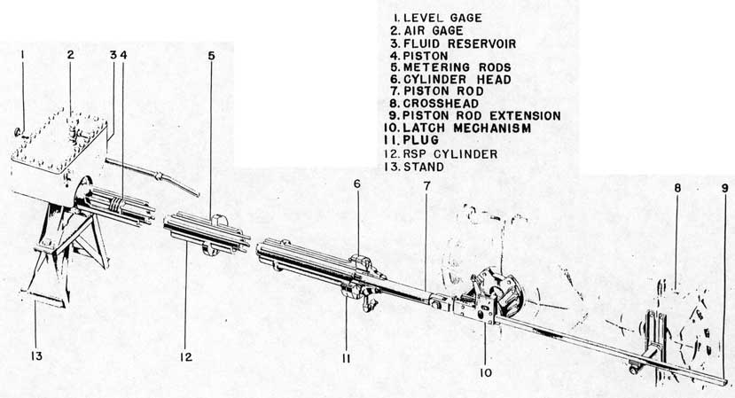
3-60. The RSP cylinder assembly, figure 3-10, includes the fluid reservoir and the cylinder with its piston and metering rods. The single walled, RSP cylinder (12) - flanged on both ends - is supported by the engine structure. The forward end of the cylinder is bolted to the fluid reservoir (3). The reservoir is provided with an air gage (2), a liquid level gage (1), and a globe valve at the bottom for drainage. A welded stand (13) supports the reservoir. The other end of the cylinder mounts the cylinder head (6) through which the piston rod (7) passes. The head has one operating pressure port, the bottom port, which is always open to the line running to the RSP valve. The outboard port is stopped with a plug (11). A vent valve is installed at the top port of the head.
3-61. The piston (4) of the RSP cylinder moves within the cylinder during launchings. It is a piston provided with holes through which run the four metering rods (5). The piston is towed through the hydraulic oil filling the cylinder by means of the piston rod extension (9). The four tapered metering rods are held in the cylinder by being threaded into the cylinder head at their smaller ends; and by nuts at their larger ends, after they pass through the fluid reservoir. The taper of the rods causes an increase of the clearance between the rods and the piston orifices as the piston is pulled toward the head. The pressure within the cylinder thus remains constant throughout he stroke, the orifice size increasing as velocity increases. The piston rod passes through the cylinder head and terminates in a fitting by which it attaches to the piston rod extension. The piston rod extension passes through the latch mechanism (10).
3-62. The latch mechanism is a knuckle-jointed, cam-actuated, uncoupling device which provides the direct connection between the RSP cylinder piston and the crosshead (8) to convert speed of the cross-head into a pressure in the RSP cylinder. The rod extension is coupled by the latch mechanism to the crosshead and moves, with the crosshead pulling the piston, until the crosshead has traveled a predetermined distance. At the end of the protected run of the crosshead (9 feet 2 inches), a fixed cam mounted on the engine structure actuates the quick release latch to release the rod extension because of the shorter stroke of the RSP.
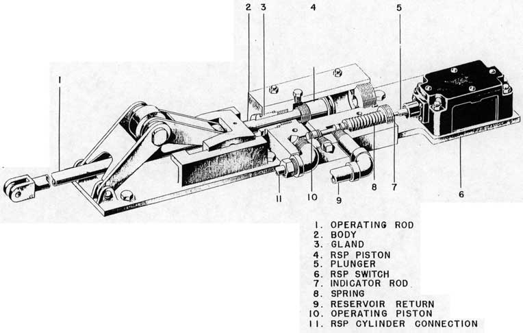
3-63. The RSP valve assembly, figure 3-11, consists essentially of the RSP valve and the RSP switch(RSP). The RSP valve is a pilot operated valve. The body (2) of the valve is mounted on the bedplate of the
mechanical cutoff. Two hydraulic oil lines enter the valve from the RSP cylinder. The high-pressure line (11) admits oil to the face of the operating piston (10). The low-pressure line (9) admits oil from the hydraulic reservoir to the opposite end of the operating piston chamber. The operating piston is spring loaded and is provided with an indicator rod (7) which serves both to indicate the position of the piston and to depress the plunger (5) of the RSP switch (6) when the operating piston moves to cutoff position. The spring (8) functions to hold the operating piston closed at any pressure below 500 psi and allows the operating piston to move to cutoff position immediately when elevated pressure (over 500 psi in the RSP cylinder) is reached. The spring further functions to return the operating piston to standby when the pressure falls below 500 psi. A single passage runs from the operating piston chamber to the piston chamber. The O-ring sealed RSP piston (4) is moved to the cutoff position by the pressure of the fluid if the operating piston is moved by the elevated RSP pressure to open the passage. The rod of the piston extends, through a packed gland (3), to the mechanical cutoff and is directly connected to the cutoff crosshead and operating rod (1) of the mechanical cutoff. Movement of the piston to the cutoff position returns the firing operating valve to standby by means of this mechanical cutoff connection.
3-64. The RSP switch (CSP) is mounted on the mechanical cutoff bedplate so that the indicator rod of the RSP valve just clears the switch plunger with the valve in standby and the switch closed. When the valve moves to cutoff position, the indicator rod opens the RSP switch.
3-65. During a normal shot of the catapult the hydraulic pressure in the runaway shot preventer cylinder rises at the beginning of the stroke and remains nearly constant throughout the remaining operating stroke of the runaway shot preventer. The maximum pressure developed increases with end speed and is about 425 psi for a 105 knot shot. At approximately 9 feet 2 inches of crosshead travel, the runaway shot preventer cylinder piston rod is released from the crosshead when the quick-release latch is actuated by stroking a fixed cam positioned for that purpose. The latch mechanism is automatically reset during retraction when the latch roller rises off the cam, allowing the latch to engage a slot in the extension rod.
3-66. During a runaway shot the hydraulic pressure in the runaway shot preventer cylinder rises abnormally. When the pressure exceeds 500 psi, the operating piston of the runaway shot preventer valve moves to the cutoff position allowing pressure to be applied to the oversize area of the cutoff piston and also actuating the RSP switch (CSP). The RSP valve
29
cutoff piston is attached to the mechanical cutoff and, when pressurized, will move the firing operating valve to standby position. The catapult is then cut off in the normal manner. The "FIRST READY" signal (white light) cannot be given until the operating piston of the runaway shot preventer valve and the runaway shot preventer switch (CSP) are in the standby position.
CAUTION
After a runaway shot, prior to the next launching, check the CSP switch and the runaway shot preventer valve operating piston for correct position to prevent the occurrence of a "slow" shot.
The runaway shot preventer gives positive protection for launching pressures of 1900 psi and above. Because of this, the H8 catapults shall not be operated with launching pressures below 1900 psi, except when making "no load" shots at 750 psi.
3-67. SHUTTLE.
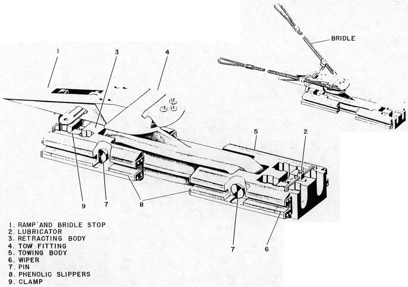
3-68. The shuttle, figure 3-12, sliding in a fixed launching track, provides an attachment - the tow fitting - for the airplane towing bridle, through which launching forces are transmitted to the airplane. The shuttle consists primarily of three parts; namely, the towing body (5), the retracting body (3), and the tow fitting (4). These three sections are fastened together by steel pins (7) to allow for slight track irregularities. A clamp (9) is provided at each section for securing the swaged: terminals in place. Molded phenolic, slippers (8) are used for the sliding bearings and are fitted in the fore and in the aft sections of the shuttle. To prolong the life of the slippers, a wiper (6) plus a lubricator (2) are provided at each end of the shuttle to lubricate and clean the track. A ramp with a bridle stop (1) is attached to the retracting body (3). The bridle stop serves as a means of arresting the bridle or pendant at the end of the catapult launching run. The ramp protects the shuttle from damage by the airplane.
3-69. CABLES.
3-70. Multiple strand, wire rope cables are used in the drive system to transmit towing, braking, and retrieving forces from the engine to the shuttle. Two towing cables of 1 1/2-inch diameter and two retrieving cables of 1 1/4-inch diameter are used. The cables are furnished with attached, swaged terminals for the shuttle end and are of sufficient length to reeve the drive system. Exact cable lengths must be measured for each catapult on installation, and the sockets for attaching them to their respective positions
to the cable tensioner cable crossheads and the cable whip damper crossheads must be poured in the catapult compartment during installation.
3-71. HOLDBACK AND RELEASE UNITS.
3-72. The holdback and release unit is used to secure the plane against forward motion prior to launching. There are two types of holdback and release units used. Information as to the type of holdback and release units used and as to sizes of their component parts is obtained from the applicable catapult bulletins issued by the Bureau of Aeronautics.
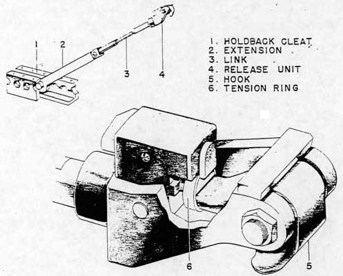
3-73. One type of holdback and release unit used, figure 3-13, is a hook-link combination employing a tension ring (6) to hold the hook (5) in a position such that the assembly forms a rigid link with the ring unbroken. When the ring breaks at a predetermined link tension, the hook is free to rotate to release the airplane. Tension rings are designed to hold the airplane safely against thrust and bridle tension, yet are not strong enough to cause excessive loads on the airplane structure when the catapult is fired. The hook end, the release unit (4), attaches to the airplane holdback shackle and the link end slips into and engages a slot in the holdback cleat (1). Tension rings are furnished to suit particular airplane requirements. The included angle between the unit and the deck, with the bridle tensioned, should not exceed 35 degrees. To adapt the holdback and release unit to airplanes having their holdback shackle so located that this minimum angle would be exceeded on unit installation, an extension (2) is furnished for installation between the links (3) and the holdback cleat. The holdback unit is furnished with two holdback links of different lengths to provide holdback unit overall adjustments in one foot increments.
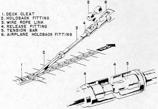
3-74. The other type of holdback and release unit used, figure 3-14, is identical in function but employs a tension bar as the release element. The tension bars are also designed to resist thrust and bridle tension yet are not strong enough to cause excessive loading on the airplane when the catapult is fired. The tension bar (5) serves as the link between the airplane holdback fitting (6) - an integral part of the airplane - and the holdback and release assembly. The holdback and release assembly provides a release fitting (4) at one end to engage the tension bar and a holdback fitting (2) at the other end to engage a slot in the deck cleat (1). The two fittings are joined by a link of wire rope (3).
3-75. LAUNCHING BRIDLES OR PENDANTS.
3-76. A launching bridle or pendant, figure 3-12, is
used to transmit launching forces from the shuttle to
30
Figure 3-12. Shuttle
31
Figure 3-13. Holdback and Release Unit - "D" Ring Type
Figure 3-14. Holdback and Release Unit - Tension Bar Type
32
the airplane. They are of a length suitable to obtain the proper line of force application relative to the airplane center of gravity and to clear the airplane structure and armament. They are proof-loaded to insure integrity of the splice. Eyes are of suitable size to engage and shed properly from the airplane towing hooks and shuttle tow fitting.
3-77. In general, a different bridle or pendant is required for each model of airplane. It is necessary to maintain an adequate stock of bridles and pendants on hand, for each model of airplane to be launched, to provide for quick replacement between successive launching operations. An initial allotment of bridles and pendants is furnished with each catapult. Additional stock must be requisitioned as required.
3-78. ARRESTING SYSTEM.
3-79. The function of the arresting system is to contain, control, and direct the forces necessary to brake the catapult and to return it to battery position ready for the next launching. The arresting system consists essentially of the following:
a. The Constant Pressure Valve
b. The Air Trap Cylinder
c. The Retracting Accumulator
d. The Retracting Valve
e. The Bypass Valve and Mechanical Controls
f. The Hydraulic Stops
g. The Operating Valves
h. The Pressure Indicator
3-80. CONSTANT PRESSURE VALVE.
3-81. The constant pressure valve, figure 3-15, meters and restrains the flow of fluid from the braking cylinder to the retracting gravity tank during the braking stroke thus setting up a considerable back pressure in the brake cylinder to resist the momentum of the ram and drive system and bring them to a stop.
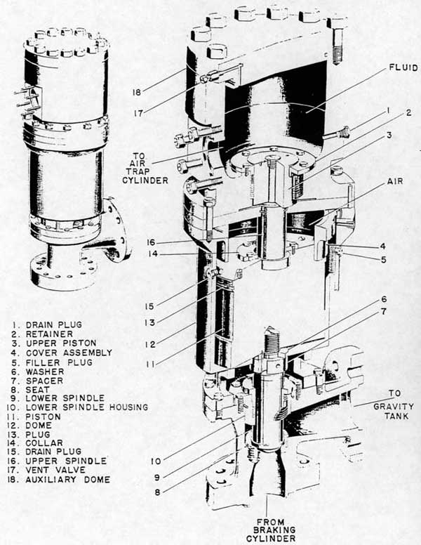
3-82. The constant pressure valve is a pneumatically loaded, check valve with a limited lift. It is mounted on the body which houses the bypass valve and retracting valve. The constant pressure valve lower port is open to the braking cylinder. The other flanged port leads to the retracting gravity tank. The lower spindle (9) moves in the V-ring packed, lower spindle housing (10) against the seat (8) to seal the lower port. The valve dome (12) is bolted to the constant pressure valve body. The dome has a cover assembly (4) packed to contain the air charge. The dome is provided with a filler plug (5) and a drain plug (15). Within this dome is a floating piston (11) which pushes against the floating lower spindle of the valve. Travel of the lower spindle is adjustable by means of
the washer (6) and the spacer (7). The piston is sealed against loss of the air charge of the dome by an O-ring. The piston is provided with plugs (13) for lifting during maintenance operations. Held in the piston by the collar (14) is the upper spindle (16) and the upper piston (3). The upper piston extends through a packed retainer (2) into the auxiliary dome (18). A vent valve (17) and drain plug (1) are provided in the auxiliary dome cover. The auxiliary dome is bolted to the dome and has a single port open to a line (the 4-inch, double extra heavy line) running to the air trap cylinder. An air line to charge the valve dome is provided. Movement of the floating spindle (the lower spindle) is directly observable through openings in the valve body.
3-83. With the engine ready to fire the auxiliary dome is solidly filled with fluid and the dome is charged with air at 260 psi pressure. This air pressure is acting on the piston which seats the floating spindle to close the valve.
3-84. When the "FIRE" button is pressed and the piston valve opens to launching accumulator pressure the air trap cylinder, the auxiliary dome, and the 4-inch, double extra heavy line connecting them is also subjected to the same pressure. This condition exists until cutoff occurs, at which time the piston valve closes and the elbow check valve opens, venting the above units to the gravity tank. The clapper valve prevents pressure peaks in the auxiliary dome by metering the pressure flow from the piston valve to the air trap cylinder.
3-85. During the power stroke the floating spindle is kept seated by the dome pressure acting on the piston. At the start of the brake stroke (bypass valve closed), the pressure exerted by the fluid trapped in the braking cylinder and ram lifts the floating spindle to its maximum height for a short period relieving the peak pressure. After this initial lift the floating spindle assumes its floating status being neither closed against its seat nor open against its housing. The restricted flow of the braking fluid through this opening creates a back pressure on the ram bringing the system to rest. At the end of the brake stroke, the dome pressure forces the spindle against its seat readying the valve for another launching cycle.
3-86. In the event of a "no-cutoff" launching, accumulator pressure would remain in the auxiliary dome to provide additional force on the spindle. This additional force is gained through the 4-inch, double extra heavy line running from the elbow check valve to the constant pressure valve. This additional force would reduce the normal orifice sufficiently to build up additional braking pressure in the ram to bring it to a stop.
33
Figure 3-15. Constant Pressure Valve
34
Figure 3-16. Air Trap Cylinder
3-87. AIR TRAP CYLINDER.
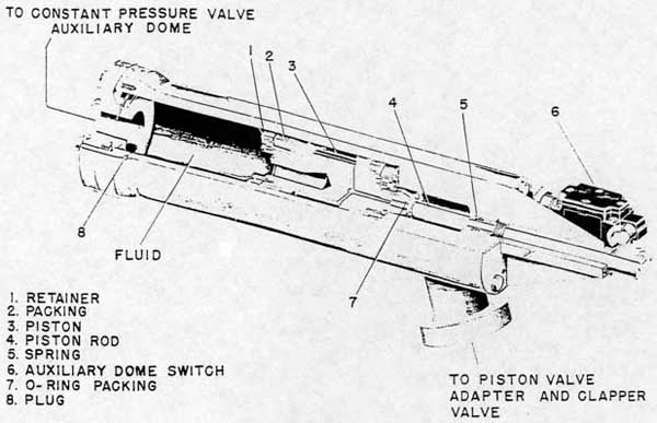
3-88. The function of the air trap cylinder, figure 3-16. is to segregate the launching fluid (containing entrapped air) from the solid fluid contained in the 4-inch, double extra heavy line and in the constant pressure valve auxiliary dome. This is accomplished by means of a floating piston (3) which is housed within the cylinder and is packed at both ends with V-ring packing (2). A hollow piston rod (4) is fastened to one end of the piston and extends externally from the air trap cylinder where it engages the auxiliary dome switch (6) mounted on a bracket. The rod serves both as a means to detect fluid leakage by the piston packing and to indicate the position of the piston in the air trap cylinder.
3-89. Under normal conditions, with the catapult in the battery position, the piston will maintain the limit switch in the closed position and thereby permit the "FIRST READY" circuit to be energized. If the piston fails to return to the above position, the "FIRST READY" circuit cannot be energized, indicating that the 4-inch, double extra heavy line has air entrapped in the fluid. This condition must be remedied by opening all vents in the line and filling it solidly with fluid by means of the drain pump.
CAUTION
Keep the filling valve in the 4-inch, double extra heavy line closed tightly. Open it only to fill the system.
3-90. RETRACTING ACCUMULATOR.
3-91. The retracting accumulator receives and stores the fluid from the retracting pumps and delivers it to the retracting valve.
3-92. The retracting accumulator is a high-pressure, cylindrical, steel vessel which is flanged at each end. A cap on the top of the accumulator contains the air charging line, a relief valve, and the connection for the liquid level gage. The manifold is connected to the bottom flange and has two ports, one from each of the retracting pumps. The manifold is furnished with a drain valve and is piped directly to the retracting valve.
3-93. The retracting fluid is pumped from the retracting gravity tank into the retracting accumulator via the manifold. The retracting accumulator contains an initial charge of compressed air and the hydraulic output of the pumps further compresses the air charge
35
to the required pressure. The flow of the retracting fluid to the engine ram is controlled by the retracting valve.
3-94. RETRACTING VALVE.
3-95. The retracting valve, figure 3-17, controls the admission of retracting fluid from the retracting accumulator to the braking cylinder to bring the system back to battery position after firing the catapult. The valve is a hydraulically operated poppet type valve with its operating piston (3) moving within a body (4) which is secured to the bypass valve body by means of a locknut (5). The operation of the retracting valve is controlled by an operating valve which is controlled by a pushbutton-actuated, air solenoid valve.
3-96. During the firing and braking strokes, the retracting valve is kept in the closed position due to retracting accumulator pressure acting on the unequal areas of the upper surface of the piston (1) and the lower surface of the poppet. To retract, the "RETRACT" pushbutton located on the deck edge control box is held down. This actuates a solenoid valve which operates an operating valve and delivers retracting accumulator pressure to the larger area of the piston of the retracting valve thus pushing the valve stem (1) off its seat and admitting retracting accumulator pressure to the braking cylinder. Rapid valve opening with consequent slamming is avoided by a fluid metering orifice between the metering disc (2) and the valve body. The retracting fluid pushes against the engine ram and returns the catapult to battery position.
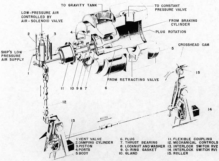
3-97. BYPASS VALVE AND MECHANICAL CONTROLS.
3-98. The functions of the bypass valve, figure 3-18, are: to permit the flow of non-flammable fluid from the braking cylinder to the retracting gravity tank during the power stroke, to close and seal off this flow to the gravity tank during braking, and to close and seal off the gravity tank from fluid under retracting pressure during retracting.
3-99. The bypass valve is a rotary type valve containing an internal rotatable plug (6) which has four through ports (4). Rotation of the plug by its mechanical controls will either align these ports with similar ports in the valve body (allowing passage of fluid to the gravity tank), or seal off the passage as necessary to produce the desired catapult operation. A thrust bearing (7) is incorporated in the valve construction to aid in plug rotation. The plug shaft is held in the valve body (5) by a locknut and washer (8) and is positioned and sealed by a V-ring packed
gland (10) furnished with an O-ring gasket (9).
3-100. The mechanical controls (12) consist of a linkage and a damping cylinder (2) and are connected to the shaft of the bypass valve plug by a flexible coupling (11). The damping cylinder is actuated by ship's low-pressure air and is provided with twin air ports and a vent valve (1). The linkage is actuated either mechanically by the cam on the underside of the crosshead for braking or electrically through the action of the damping cylinder air solenoid valve on the damping cylinder for retracting.
3-101. For braking, crosshead cam action on the roller (15) of the mechanical linkage causes the bypass valve plug to rotate thus cutting off the flow of fluid to the retracting gravity tank. The damping cylinder cushions this valve action by virtue of the ship's low-pressure air acting on the smaller rod-end area of a piston (3) within the damping cylinder. The fluid, thus cut off from the gravity tank, is forced to overcome the fluid flow resistance offered by the constant pressure valve. This resistance then brakes the engine. At the end of the power stroke the crosshead cam starts the brake stroke by actuating the bypass valve linkage and opens the "RV1" switch (14). Opening the "RV1" switch de-energizes the firing relay, extinguishes the firing lights, and permits the retracting circuit to be energized when the retracting button is depressed. If the "RV2" switch (13) is actuated at this time the "FIRST READY" lights will be extinguished; if not, they will be extinguished when the "RETRACT" button is depressed.
3-102. For retracting, pushing the "RETRACT" button insures that the bypass valve is fully closed and retracts the engine. The button actuates the damping cylinder solenoid valve which admits ship's low-pressure air to the top of the damping cylinder. This pressure, acting on the larger area of the piston in the damping cylinder, will move the linkage slightly beyond the position to which it was moved by the crosshead cam. When the bypass valve reaches the fully closed position, closing the RV2 switch, the retracting solenoid valve will be energized, actuating the retracting operating valve that opens the retracting valve to retract the catapult. Releasing the "RETRACT" button (with the crosshead at any point in the stroke) will de-energize the retracting solenoid, vent the retracting operating valve, and close the retracting valve thus stopping the retraction. Releasing the "RETRACT" button will at the same time de-energize the damping cylinder solenoid valve, vent the upper side of the damping cylinder through an orifice to delay valve opening, and - if the crosshead is not in the brake stroke - permit the bypass valve to open fully. In an emergency this cycle may
36
Figure 3-17. Retracting Valve
37
Figure 3-18. Bypass Valve and Mechanical Controls
38
Figure 3-19. Hydraulic Stops
39
Figure 3-20. Operating Valve
be accomplished at any position along the retracting stroke. Retraction is to be continuous and uninterrupted except in emergencies.
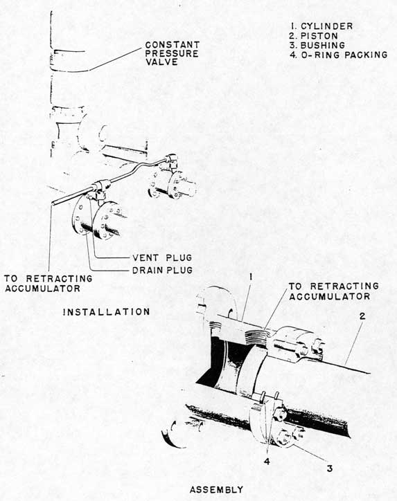
3-103. HYDRAULIC STOPS.
3-104. The function of the hydraulic stops, figure 3-19, is to act as a shock absorber to reduce any possible impact of the crosshead on the engine structure. The stops are hydraulic, cylinder-piston devices connected by piping to the retracting accumulator and secured to the ship's structure. There are two stops identical in construction and operation. Each stop consists of a cylinder (1), an operating piston(2), and a bushing (3) which functions as a gland to seal the cylinder. If the crosshead strikes the extended pistons, the retarding forces of the contained fluid and the throttling orifices act to absorb the impact.
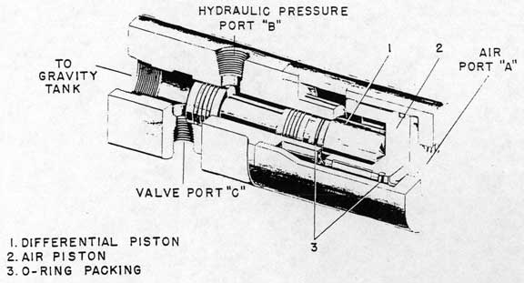
3-105. OPERATING VALVES.
3-106. There are two of these valves, figure 3-20, installed on the catapult. They are used for bridle tensioning and retracting as previously mentioned. The function of the valve is to control the flow of high-pressure fluid actuating the bridle tensioning pistons (for bridle tensioning), and the retracting valve (for retracting). The valve contains two pistons; namely, a differential, hydraulically operated piston (1) and an air operated piston (2). Under normal
operation, port "C" is sealed off from port "B" due to hydraulic pressure action on the differential piston. When actuated, air pressure through port "A" forces the air piston to overcome the hydraulic pressure on the differential piston, moving both pistons and opening a passage for hydraulic pressure from port "B" to port "C". With venting of air pressure, both pistons are returned to their original positions by hydraulic pressure from port "B".
3-107. PRESSURE INDICATORS.
3-108. Two Bacharach pressure indicators, figure 3-21, are installed on each catapult; one to indicate engine cylinder pressure and the other to indicate brake cylinder pressure. Instructions for operation and maintenance of these indicators are furnished by the manufacturer. The method of interpretation of indicator card readings will be found in Section VII of this manual.
3-109. FOUR-WAY VALVE.
3-110. The four-way valve, see paragraph 3-14, has a function in the arresting system in addition to its function in the launching system. During the braking and retracting cycles of the engine, fluid from the retracting accumulator passes through the four-way valve to the top of the elbow check valve holding the elbow check valve open. The fluid in the main engine
40
Figure 3-21. Pressure Indicator
41
cylinder is returned to the launching gravity tank through the open elbow check valve.
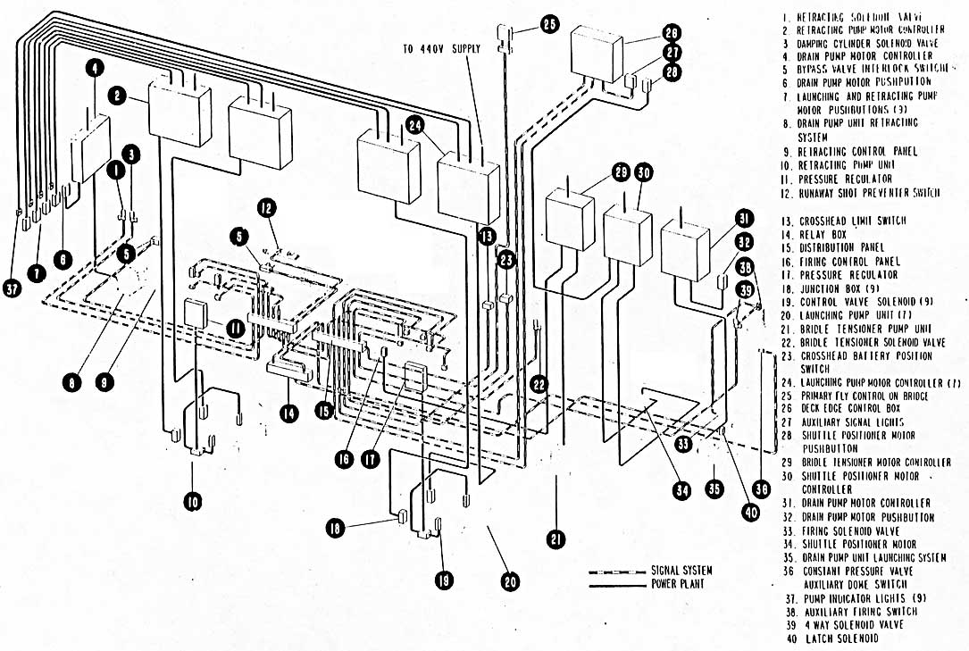
3-111. POWER PLANT AND SIGNAL SYSTEM.
3-112. PUMPS.
3-113. The function of the pumps, figure 3-22, is to convert the power of their electric motors into fluid pressure to compress the air hydraulically in the accumulators to the pressure required for operation of the catapult and to regain this pressure after launchings. Pumps are positive displacement, high-pressure, piston, oil pumps used as constant displacement type, fluid pressure generators.
3-114. Each pump unit consists essentially of a foot-mounted, constant displacement, axial piston pump equipped with a relief valve and an integral, electrically operated, positive action pilot valve for delivery control The pump is driven by a separately mounted electric motor through a flexible coupling.
Note
For more detailed information, upkeep and construction refer to the applicable pump manuals. See paragraph 5-55. These manuals shall be kept with the catapult log for ready reference.
3-115. During operation the pump applies a force to the liquid; the relief valve limits the pressure to a predetermined and safe maximum; and the delivery control provides full or zero delivery at the output connection by remote control, without the need for starting or stopping the pump. The pumps run continuously during operations; design of the pump control mechanism being such that the pump returns its discharged fluid to the gravity tank during catapult standby position by the action of the relief type control valve. All pumps discharge at full capacity to the accumulator when the accumulator pressure is less than that set for the accumulator by an automatic pressure regulator. The pressure regulator, operated by the drop of pressure in the accumulator, actuates a solenoid control valve on the pump causing the pump control valve to close and delivering the pump discharge to the accumulator. When set pressure is reached in the accumulator, the pump control solenoid is de-energized by the pressure regulator and the pump control valve again opens to the pump return line.
3-116. Each pump is protected against overload by a relief valve provided on the discharge side. Each pump is provided with a discharge pressure gage mounted on the pump pressure gage panel for indication of proper pump operation. Each pump case is provided
with a drain connection at its lowest point and with a vent connection at its highest point. The vent connection is connected to the pump suction line.
CAUTION
The pump discharge pressure gages shall not be construed to indicate accumulator pressure.
3-117. PUMP MOTORS AND CONTROLLERS. The driving motor for each hydraulic pump is rated 150 H.P. at 885 rpm. Motors operate on 440 volts A.C. Controllers provide proper control of starting and stopping of the motors. Lights are provided at each main power plant pump pushbutton station as a means of indicating to the catapult operator whether the particular pump is in operation.
3-118. PRESSURE REGULATORS.
3-119. Pressure regulators, figures 3-24 and 3-25, are mounted on both the firing and retracting control panels to provide a means of controlling the delivery of fluid, at a set pressure, to the respective accumulators. A pressure regulator consists of a dual pressure regulator assembly, each containing a Bourdon rube and a relay. Selection of the regulator assembly to be used is provided by a two-position selector switch, and an indicator light shows which assembly is selected. Two handwheels provide manual control of the pressure setting. Counterclockwise rotation will increase pressure to any value within the regulator range of approximately 750 to 3750 pounds per square inch for the launching regulator, up to about 1000 psi with the retracting regulator. The pressure regulator operates only on 440 volts A.C. In operation, with the regulator supply line energized and with the regulator selector switch in either the "REGULATOR NO. 1" or "REGULATOR NO. 2" position, the regulator contactors will operate to control the pump pilot valve solenoids. If the accumulator pressure is lower than the regulator pressure control handwheel setting, the Bourdon tube operated mechanism will act to close the circuit in the pump pilot valve solenoid supply line thus energizing the solenoid to cause the pump's control valve to close, permitting the pump to deliver full capacity to the accumulator. The pump will continue to deliver fluid into the accumulator, compressing the air mass, until the required pressure determined by the regulator handwheel setting has been attained. At this time, the Bourdon tube operated mechanism will operate to de-energize the pump pilot valve solenoid thus permitting the pump control valve to return to its original open position, causing the pump delivery to be bypassed to the gravity tank. The regulator pressure control handwheel for the energized regulator is directly beneath the indicator light at each panel.
42
Figure 3-22. Power Plant and Signal System - Electrical
43
CAUTION
Although operations may be conducted with one or more hydraulic pump units standing idle, no pump driving motor shall be started until pressure regulator has been set to minimum pressure and regulator shall not be returned to set pressure until motor has attained full speed.
3-120. DRAIN PUMP.
3-121. The function of the drain pump is to drain the catapult hydraulic system. It is further used to charge the constant pressure valve upper dome, the air trap cylinder, and the interconnecting 4-inch line. A flexible hose is furnished for use with the pump. The drain pump unit consists of a hydraulic pump directly connected through a flexible coupling to an electric driving motor, both mounted on a common bed-plate. The pump is a rotary gear, low-pressure pump. The motor is furnished to operate on 440 volts A.C. The controller provides proper control of starting and stopping of the motor.
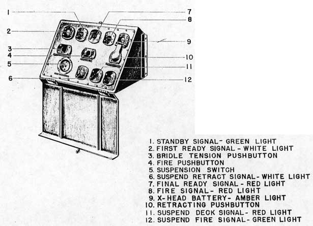
3-122. DECK EDGE CONTROL BOX.
3-123. The deck edge control box, figure 3-23, contains pushbuttons for bridle tensioning (3), firing (4), and retracting (10) of the catapult. Mounted on the box are the following labeled signal lights to indicate operation: white for "FIRST READY" (2), green for "STANDBY" (1), red for "FINAL READY" (7), red for "FIRE" (8), and amber for "X-HEAD BATTERY" (9). An emergency suspension switch (5) with a red indicating light (11) is provided for suspending catapult operations along with suspension signal lights for indicating other sources of suspension; namely, a white light from retracting control panel for "SUSPEND-RETRACT" (6), and a green light from firing control panel for "SUSPEND-FIRE" (12). The shuttle positioner pushbutton box is located adjacent to the deck edge control box with "FORWARD" and "REVERSE" pushbuttons. An auxiliary deck edge signal box is provided, visible to the catapult officer on the flight deck, containing three operational signal lights; white for "FIRST READY", green for "STANDBY", and red for "FINAL READY".
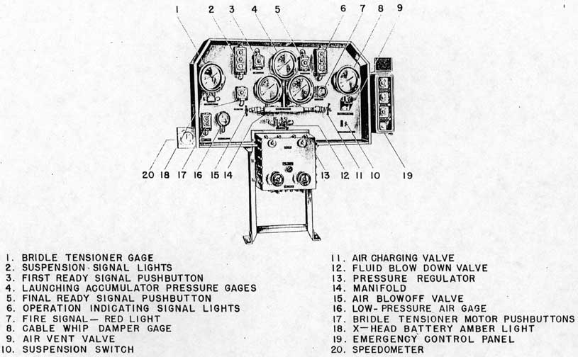
3-124. FIRING CONTROL PANEL.
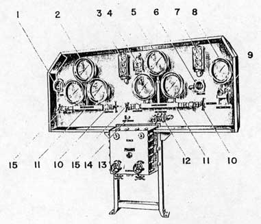
3-125. The firing control panel, figure 3-24, contains pushbuttons (17) for operating the bridle tensioner motor and pushbuttons for the "FIRST READY" (3) and "FINAL READY" (5) signal lights. The panel has signal lights (6) with colored and labeled plastic lenses to indicate operation of the catapult as follows: white for "FIRST READY", green for "STANDBY",
red for "FINAL READY", red for "FIRE" (7), and amber for "X-HEAD BATTERY" (18). The panel has an emergency suspension switch (10) for suspending catapult operations and suspension signal lights (2) indicating sources of suspension; namely, a green light from firing control panel for "SUSPEND-FIRE", a white light from retracting control panel for "SUSPEND-RETRACT", and a red light from deck edge control box for "SUSPEND-DECK". Mounted on the panel are: three launching accumulator pressure gages (4) connected to a common manifold (14) which has an air charging valve (11) at one end and an air blowoff valve (15) at the other end; a fluid blowdown valve (12); a low pressure air gage (16); the pressure regulators (13) for controlling the pressure delivery of the pumps in the launching system; the cable whip damper gage (8) with its air vent valve (9); and the bridle tensioner gage (1). Mounted adjacent to the firing control panel is the electric speedometer (20). See paragraph 3-135.
Note
An emergency fly control bypass switch (FB) will be installed on the panel by the Bureau of Ships.
An emergency control panel (19), secured to the firing control panel, contains pushbuttons for bridle tensioning, firing, and retracting the catapult in the event of damage to the deck edge control panel. In addition, a switch (maintained in the open position) for connecting the emergency control panel to the signal system is provided. A glass plate is used to seal off the pushbuttons and switch from use and is to be broken only in case of damage to the deck edge control box.
3-126. RETRACTING CONTROL PANEL.
3-127. The retracting control panel, figure 3-25, Contains a pushbutton (4) for operating the "FIRST READY" signal. The panel has signal lights (7) with colored and labeled plastic lenses to indicate operation of the catapult as follows: White for "FIRST READY", green for "STANDBY", red for "FINAL READY", and red for "FIRE" (6). It has a suspension switch (14) for suspending catapult operations and suspension signal lights (3) indicating sources of suspension; namely, a white light from the retracting control panel for "SUSPEND-RETRACT", a green light from the firing control panel for "SUSPEND-FIRE", and a red light from deck edge control box for "SUSPEND-DECK". Mounted on the panel are: three retracting accumulator pressure gages (5) connected to a common manifold (11) which has an air charging valve (10) at one end and an air blowoff
44
Figure 3-23, Deck Edge Control Box
45
Figure 3-24. Firing Control Panel
46
Figure 3-25. Retracting Control Panel
47
valve (15) at the other end; three constant pressure valve pressure gages (2) connected to a common manifold which has an air charging valve at one end and an air blowoff valve at the other; a low-pressure air gage (1); a cable tensioner gage (8) with an air vent valve (9) and a charging valve (at rear of panel); a fluid blowdown valve (12) for the retracting accumulator; and a pressure regulator (13) for controlling the pressure delivery of the pumps in the retracting system.
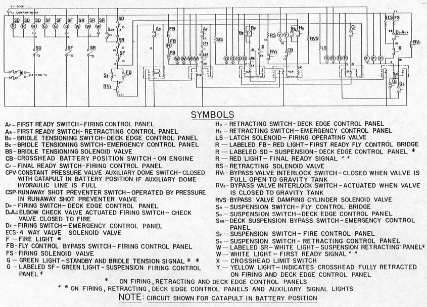
3-128. SIGNAL SYSTEM-LAUNCHING CYCLE.
3-129. To fire the catapult the following signal sequence shall be followed. See figures 3-22 to 3-26 inclusive.
a. The firing control panel operator depresses his "FIRST READY" pushbutton (AF) and the retracting control panel operator depresses his "FIRST READY" pushbutton (AR). If the catapult is ready for operation, the white "FIRST READY" light shall light at each of the four signal stations (deck edge control box, auxiliary deck edge signal box, firing control panel and retracting control panel). Both buttons must be depressed, though not simultaneously, to obtain the white "FIRST READY" light.
b. With the white "FIRST READY" light on at the deck edge control box, the deck edge operator, on signal from the catapult officer, depresses his "BRIDLE TENSION" pushbutton (BD) thus tensioning the bridle and lighting the green "STANDBY" light at each of the four signal stations.
c. With the green "STANDBY" light on at the firing control panel, the firing control panel operator now depresses his "FINAL READY" pushbutton (CF) lighting the red "FINAL READY" light at each of the four stations and energizing the latch solenoid, lifting the locking pin.
d. With the red "FINAL READY" light on at all stations, the deck edge operator, on signal from the catapult officer, depresses his "FIRE" pushbutton (DD). When the "FIRE" button is depressed, the four-way valve solenoid valve is energized which admits low-pressure air to the four-way valve. The valve is moved to the fired position which admits retracting accumulator pressure to the underside of the operating piston of the elbow check valve and vents the upper side to the launching gravity tank. The elbow check valve stem moves upward, the double disc on the lower end seals the main engine cylinder from the gravity tank, and the rod at the upper end contacts the auxiliary firing switch (DD Aux). Closing the auxiliary firing switch energizes the firing solenoid valve (FS) which admits low-pressure air to the firing operating valve. The valve moves to the fired position and admits fluid under accumulator pressure through a throttling orifice to the operating piston of the piston valve. The piston valve opens, admitting accumulator
pressure to the engine cylinder to start the launching stroke.
e. When the crosshead moves approximately 2 3/4-inches from battery position, the crosshead limit switch (X) is actuated de-energizing the bridle tensioning, final ready and latch solenoid, four-way valve, and firing solenoid valve circuits. The "FIRST READY" and "FIRE" lights remain lit. The four-way valve vents the lower side of the elbow check valve operating piston to the gravity tank and applies pressure to the top of the piston. Pressure in the engine cylinder keeps the elbow check valve closed until the end of the power stroke.
f. At the end of the power stroke, the crosshead cam depresses the mechanical cutoff control and the firing operating valve is moved to the closed position. The latch solenoid pin drops to prevent refiring and the operating piston of the piston valve is vented to the gravity tank, allowing the piston valve to close. The crosshead then actuates the bypass valve linkage which starts the brake stroke and opens the bypass valve interlock switch (RV1). Opening this switch de-energizes the firing relay which blanks the "FIRE" lights and permits the retracting circuit to be energized when retracting. If the bypass valve interlock switch (RV2) is actuated by the mechanical linkage at this time the "FIRST READY" lights will blank; if not, they will blank when retracting. The firing circuit cannot again be operated until the crosshead reaches battery position, closing the "X" switch.
g. In the event of a runaway shot, the runaway shot preventer switch (CSP) will be actuated. The "FIRST READY" signal light cannot be obtained until the CSP switch returns to standby position, thus preventing making a launching with the RSP valve in an operated position.
3-130. SIGNAL SYSTEM - RETRACTING CYCLE.
3-131. To retract the catapult the following signal sequence shall be followed: See figures 3-22 to 3-26 inclusive.
a. The retracting circuit relay cannot be energized to retract the catapult when the firing relay is energized.. The firing circuit is arranged so that the firing relay is energized from the time the "FIRE" pushbutton is depressed until the crosshead cam actuates the bypass valve linkage; therefore, inadvertently depressing the "RETRACT" button during the power run will not close the bypass valve during the launching stroke and cause an early brake stroke.
b. After the shuttle has come to a complete stop, and on signal from the catapult officer, the deck edge controls operator depresses and holds the "RETRACT" pushbutton (HD) which energizes the damping cylinder solenoid valve (RVS). which applies low-pressure air to the upper side of the damping cylinder. The piston is pushed downward, rotating the
48
Figure 3-26. Signal System - Schematic Diagram
49
bypass valve to the closed position. When the fully closed position is reached, the RV2 switch is actuated, energizing the retracting solenoid valve (RS). The retracting solenoid valve applies low-pressure air to the retracting operating valve which applies retracting accumulator pressure to the operating piston of the retracting valve, opening it and retracting the catapult. The controls operator holds the pushbutton until the crosshead reaches battery position and the crosshead closes the "CB" switch and lights the indicating lights. When the button is released, the lights blank and the retracting solenoid valve and the damping cylinder solenoid valve are both de-energized. The retracting operating valve is vented which vents the retracting valve to the gravity tank, closing it. The vent of the damping cylinder solenoid valve is blocked by a throttling orifice which delays opening the bypass valve until the retracting valve has closed, thus avoiding loss of accumulator pressure by having both valves open at the same time.
c. In the event of an emergency, the retracting button may be released at any point in the retracting stroke with the above sequence occurring except for the "CB" switch operation. Retraction is then resumed as before and the brake cylinder is to be vented before making any launchings.
d. Assuming that the crosshead is somewhere in the retraction stroke and the "RETRACT" button is released, the following sequence occurs: the retracting circuit is opened, de-energizing both the damping cylinder solenoid valve and the retracting solenoid valve. The orifice plug in the damping cylinder solenoid valve vents momentarily to delay opening the bypass valve while the retracting valve is closed, avoiding loss of accumulator pressure through the bypass valve. The bypass valve returns slowly to the open position, deactivating RV2 and closing RV1.
e. To resume the retracting cycle, the "RETRACT" pushbutton (HD) is again held down which energizes the damping cylinder solenoid valve, moving the mechanical controls to close the bypass valve interlock switch RV2 and energize the retracting solenoid valve (RS). When the crosshead reaches its fully retracted position, it will close switch "CB" on the engine and cause the amber lights on the firing control panel and deck edge signal box to light. These lights will only be on when the deck edge controls operator has the "RETRACT" pushbutton depressed and with the crosshead fully retracted.
3-132. SIGNAL SYSTEM - SUSPENSION CYCLE.
3-133. A suspension switch for holding up operations is provided at each of the four signal stations. In addition, an indicating light showing the origin of the suspension signal is provided. See figures 3-22 to 3-26 inclusive.
CAUTION
Suspension switches are for emergency use only to notify the catapult officer, catapult personnel, and others concerned that operation is suspended. The suspension switches do not, of themselves, secure the catapult.
CAUTION
If the catapult is inadvertently fired with the piston valve securing stem "in" and/or the supply valve to the firing operating valve closed, and the firing operating valve lock assembly removed; the firing operating valve will move to the fired position but the catapult will not fire. It is necessary to suspend operation, secure the catapult, and return the firing operating valve to standby. Blanking the signal system will not secure the catapult. To bring the catapult to "ready" proceed as follows. Insure that the supply valve to firing operating valve is closed tightly. De-energize signal system by opening main power switch and manually move firing operating valve to the standby position (latch solenoid pin must drop in place) by grasping Linkage aft of firing operating valve and moving it to standby position. Replace firing operating valve lock assembly. Proceed, as normally, to prepare catapult for launching.
3-134. The following examples will serve to explain the working of the suspension signal system.
a. CASE I. Assume that the catapult operators have depressed the "FIRST' READY" buttons, lighting the white "FIRST READY" light at each of the four signal stations, and then that the deck edge controls operator throws his "SUSPENSION" switch to the "ON" position. The red light labeled "SD" will light at each of the other three control panels showing the origin of the suspension and the white "FIRST READY" light will blank at all four stations.
b. CASE II. Assume that the catapult operators have depressed the "FIRST READY" buttons, lighting the white "FIRST READY" light at each of the four signal stations; and that the deck edge controls operator has depressed the "BRIDLE TENSION" button, lighting the green light labeled "STANDBY" and energizing the bridle tension solenoid valve (BS); and then that the catapult operator at the firing control panel throws his "SUSPENSION" switch to the "ON" position. The white "FIRST READY" lights will blank but the green "STANDBY" lights will remain lit, and the bridle tensioner solenoid valve will remain
50
energized. The green light labeled "SF" will light at the other three control panels showing the origin of the suspension.
c. CASE III. Assume that the catapult operators have depressed the "FIRST READY" and "FINAL READY" buttons; the controls operator depressed the "BRIDLE TENSION" button; and then that the catapult operator at the retracting control panel throws his "SUSPENSION" switch to the "ON" position. The white "FIRST READY" and red "FINAL READY" lights will blank out, the green "STANDBY" will remain on, the bridle tensioner solenoid valve will remain engaged, and the white light labeled "SR" will light at the three control panels to show the origin of the suspension.
d. CASE IV. Assuming that the necessary signals have been made and the "FIRE" button pushed, a suspension signal at this time will not stop the catapult from firing. However, inasmuch as the time interval between pushing the "FIRE" button and motion of the firing operating valve is all but instantaneous, there is little likelihood of an attempt to use the suspension switch at this time.
e. CASE V. If during the course of retracting a "SUSPENSION" switch is thrown to the "ON" position, the damping cylinder solenoid (RVS) and the retracting solenoid valve (RS) will be de-energized, and the lights indicating the source of suspension will light.
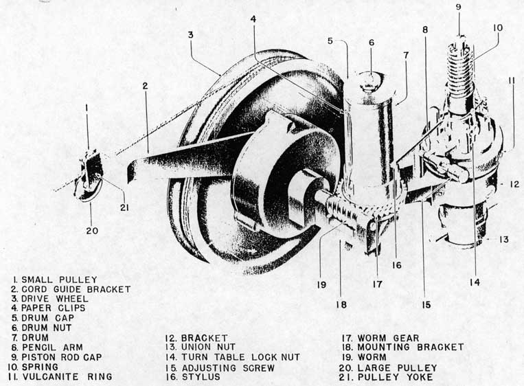
3-135. ELECTRIC SPEEDOMETER.
3-136. An electric speedometer, figure 3-24, is mounted on, or adjacent to, the firing control panel to provide an indication of shuttle end speed in knots. The end speed for each shot shall be recorded in the catapult launching log. The reading of the large sweep hand is correct only when the point of the short sweep hand is within the open white portion of the red circle.
Note
Operational launching requirements shall always be governed by applicable bulletins, never by speedometer readings.