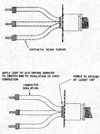
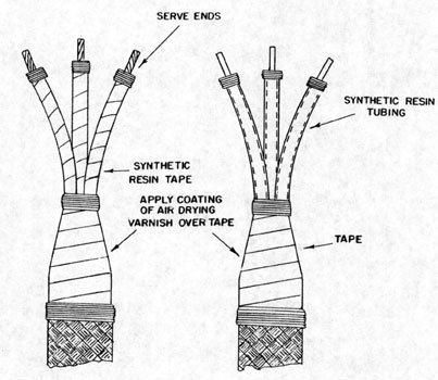
End sealing of the cable depends upon its application, but good workmanship demands a neat seal of some sort. In some instances the cable end is served, but friction tape or varnished cambric tape may be used to quick advantage to provide a neat job. (Figures 9-24 and 9-25). A coat of air-drying varnish is usually applied over the tape.
In submarine applications where pressure-proof requirements must be met, particular attention must be paid to end sealing, since improperly sealed cables may act as conduit when exposed to pressure.
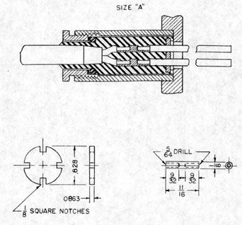
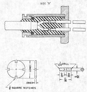
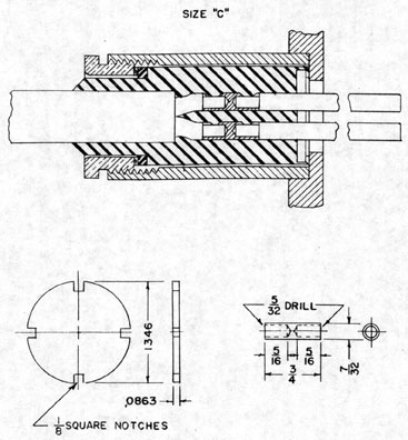
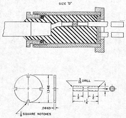
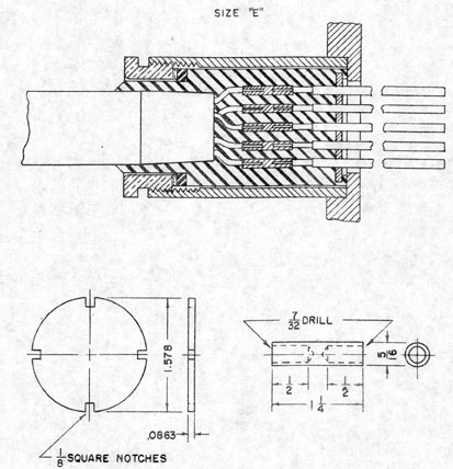
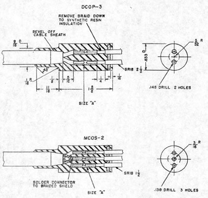
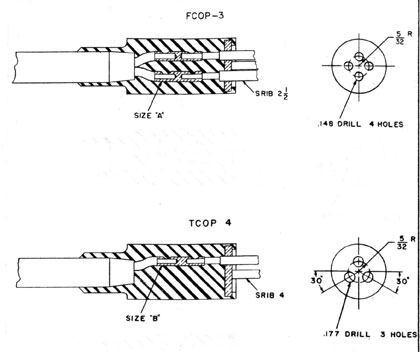
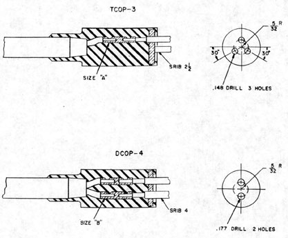
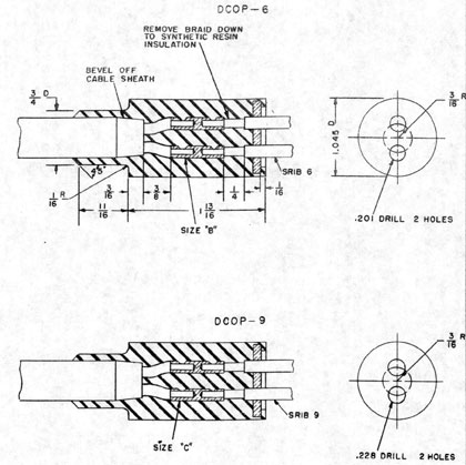
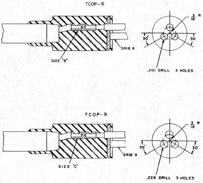
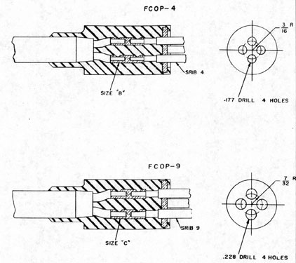
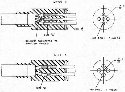
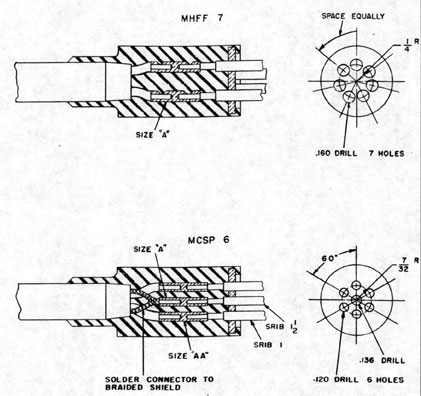
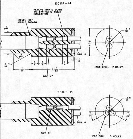
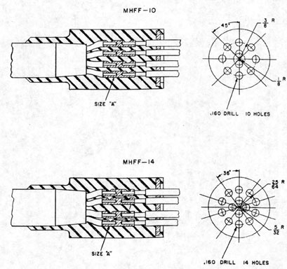
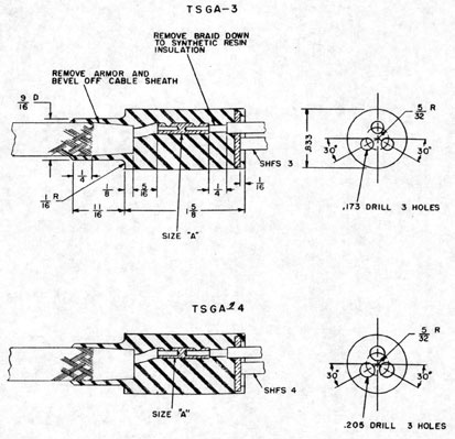
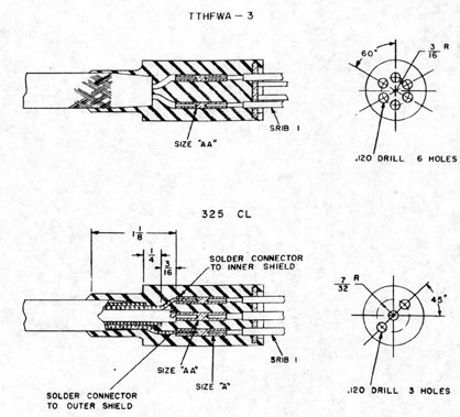
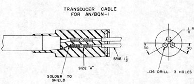
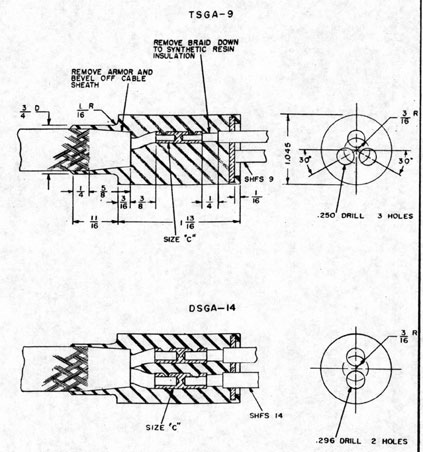
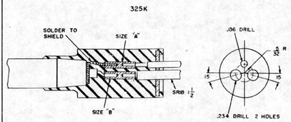
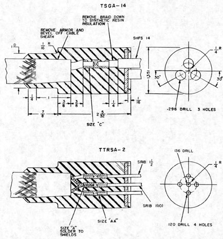
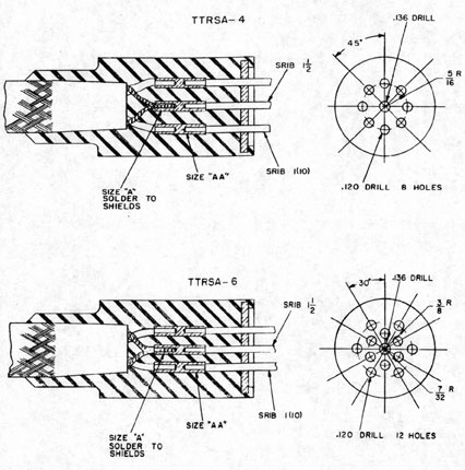
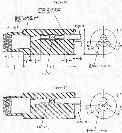
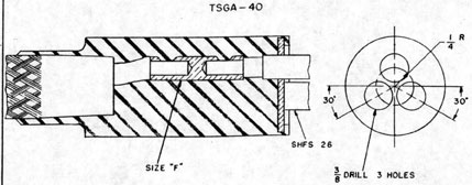
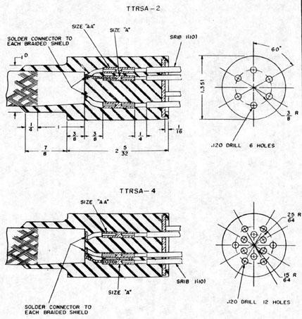
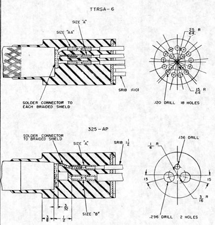
The Rubber Laboratory at the Portsmouth Naval Shipyard has developed an improved method for applying molded seals at the ends of portable cables and molded packing between the ends of cables where needed for passing a cable through a watertight bulkhead (submarine applications). The molding compound makes a satisfactory bond with both the cable sheath and the insulation on the cable conductors. Figures 9-26 to show the various arrangements and parts for commonly used cables, taken from BuShips plan #9000-S-6202-73903.
Figures 9-26 to 9-30 give dimensions and typical arrangement for tube sizes A to E. Note that type SRIB (single conductor, resin insulated, braid) and SHFS (single conductor, heat and flame resistant, switchboard) are used to bring the individual conductors out of the molded packing. Note that the continuity of shields where they appear, as for TTRSA types is maintained.
There are no general requirements for end sealing electronic cables terminating at electronic equipment or for end sealing individual conductors. BuShips plan, 9-S-5357-L is not applicable because of the crimp lug employed. However, it is important that individual conductors be properly end sealed in submarine applications.
The Portsmouth Naval Shipyard uses two methods for end sealing individual conductors. One method is used for pressure-proof applications and involve s the use of rubber tape and a rubber cement. The other is used for watertight applications and involves the use of glass fiber tape and air drying varnish.
In this first method, the conductor is
stripped and lug is placed on. The
rubber sheath is then roughed with a knife for a length of approximately 3/4". No solvents are needed to clean the conductor. Apply B. F. Goodrich "Vulcalock" cement, Navy Stock No. (L) 213-52-C1413 over the barrel of the lug and back 3/4" over the conductor sheath.
"Vulcalock" is used since it stays in liquid form during storage, while other types invariably solidify with shelf life. After applying one coat of cement, allow from 5 to 10 minutes for the cement to get tacky. Approximately 5" of electrical rubber tape (3/4" wide) is cut and split in two lengthwise. Apply a coat of cement to the tape and allow this to get tacky also. The rubber tape is then wound over the conductor, down over the barrel of the lug and then back over the conductor with a half lap. This assembly seals itself and will not delaminate.
In the second method, the lug is placed on as before and Glass Fiber Tape, (1"x .007")Navy Stock No. 17-1-2645-80, is secured to the conductor sheath with Glass Fiber Line (Navy Stock No. 17-12643-145). The line is terminated as in a lace. The tape is wound over the conductor, down the barrel of the lug and back over the conductor with a half lap. Then this end of the tape is secured with the glass fiber line. Then apply a light coat of air-drying varnish. Any type of air-drying varnish, including glyptal, may be used. This end seal is oil resistant and has very good high temperature characteristics when used with the reduced diameter cables.
9-59
FIGURE 9-24
METHODS OF MAKING UP CABLE ENDS
ENCLOSED EQUIPMENT W.T. AND N.W.T.
9-60
FIGURE 9-25
METHODS OF MAKING UP CABLE ENDS
OPEN EQUIPMENT
9-61
FIGURE 9-26
TYPICAL ASSEMBLY OF
MOLDED PACKING IN TUBE
9-62
FIGURE 9-27
TYPICAL ASSEMBLY OF
MOLDED PACKING IN TUBE
9-63
FIGURE 9-28
TYPICAL ASSEMBLY OF
MOLDED PACKING IN TUBE
9-64
FIGURE 9-29
TYPICAL ASSEMBLY OF
MOLDED PACKING IN TUBE
9-65
FIGURE 9-30
TYPICAL ASSEMBLY OF
MOLDED PACKING IN TUBE
9-66
FIGURE 9-31
ARRANGEMENTS FOR SEALING
CABLE ENDS IN
MOLDED PACKING SIZE A
9-67
FIGURE 9-32
ARRANGEMENTS FOR SEALING CABLE ENDS IN
MOLDED PACKING SIZE A
9-68
FIGURE 9-33
ARRANGEMENTS FOR SEALING
CABLE ENDS IN
MOLDED PACKING SIZE A
9-69
FIGURE 9-34
ARRANGEMENTS FOR SEALING
CABLE ENDS IN
MOLDED PACKING SIZE B
9-70
FIGURE 9-35
ARRANGEMENTS FOR SEALING CABLE ENDS IN
MOLDED PACKING SIZE B
9-71
FIGURE 9-36
ARRANGEMENTS FOR SEALING
CABLE ENDS IN
MOLDED PACKING SIZE B
9-72
FIGURE 9-37
ARRANGEMENTS FOR SEALING
CABLE ENDS IN
MOLDED PACKING SIZE B
9-73
FIGURE 9-38
ARRANGEMENTS FOR SEALING
CABLE ENDS IN
MOLDED PACKING SIZE B
9-74
FIGURE 9-39
ARRANGEMENTS FOR SEALING
CABLE ENDS IN
MOLDED PACKING SIZE C
9-75
FIGURE 9-40
ARRANGEMENTS FOR SEALING
CABLE ENDS IN
MOLDED PACKING SIZE C
9-76
FIGURE 9-41
ARRANGEMENTS FOR SEALING
CABLE ENDS IN
MOLDED PACKING SIZE A
9-77
FIGURE 9-42
ARRANGEMENTS FOR SEALING CABLE ENDS IN
MOLDED PACKING SIZE A
9-78
FIGURE 9-43
ARRANGEMENT FOR SEALING
CABLE ENDS IN
MOLDED PACKING SIZE A
9-79
FIGURE 9-44
ARRANGEMENTS FOR SEALING
CABLE ENDS IN
MOLDED PACKING SIZE B
9-80
FIGURE 9-45
ARRANGEMENT FOR SEALING
CABLE ENDS IN
MOLDED PACKING SIZE B
9-81
FIGURE 9-46
ARRANGEMENTS FOR SEALING CABLE ENDS IN
MOLDED PACKING SIZE C
9-82
FIGURE 9-47
ARRANGEMENTS FOR SEALING CABLE ENDS IN
MOLDED PACKING SIZE C
9-83
FIGURE 9-48
ARRANGEMENTS FOR SEALING
CABLE ENDS IN
MOLDED RACKING SIZE D
9-84
FIGURE 9-49
ARRANGEMENT FOR SEALING
CABLE ENDS IN
MOLDED PACKING SIZE D
9-85
FIGURE 9-50
ARRANGEMENTS FOR SEALING
CABLE ENDS IN
MOLDED PACKING SIZE C
9-86
FIGURE 9-51
ARRANGEMENTS FOR SEALING
CABLE ENDS IN
MOLDED PACKING SIZE C
9-87
FIGURE 9-52
ARRANGEMENTS FOR SEALING CABLE ENDS IN
MOLDED PACKING SIZE E
9-88
FIGURE 9-53 ARRANGEMENTS FOR SEALING
CABLE ENDS IN
MOLDED PACKING SIZE E
9-89
5. APPLYING TERMINAL LUGS.
When cutting back insulation to allow installation of lugs, remove just enough insulation so that the stripped conductor will fit the lug exactly. Take particular care not to cut any part of the conductor, since even a slight nick will weaken it and eventually cause the conductor to break. Hand wire strippers are very useful for removing insulation (See Chapter 3) or with a little experience, a sharp knife or diagonal cutter may be used efficiently.
Always use a lug large enough to fit over all strands of the conductor. In the event a lug must be used that is too small, and no alternative is offered, the following method is recommended:
Fan back the outer strands of the conductor, cut out the center strands, and form back the outer strands to fit the lug. At the present time, all lugs used on electronic installations must be soldered, with a few exceptions. Solder-less type lugs may be utilized to provide a good mechanical and electrical connection by crimping and soldering both.
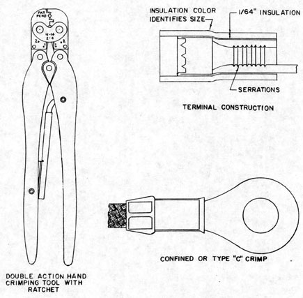
The new reduced diameter cables have a waterproofing compound (silicone grease) which fills all voids even in individual conductors. This grease makes the soldering of terminal lugs very difficult. Individual strands must be cleaned with "Decalene" (Deca-HydroNapthalene). To speed up installation work involving these cables, a solder-less terminal connector has been approved on a few installations. The connector, method of crimp, and tooling are taken up in Chapter 5. The crimp is known as the confined "C" crimp with insulation support and is manufactured by Aircraft Marine Products, Inc. The crimping tool, Figure 9-54 is equipped with a ratchet to insure a uniform crimp. The ratchet will not release until the crimping cycle is completed. The tool performs a double action; it crimps the terminal barrel to the conductors and the insulation grip to the insulation sheath. Always use the recommended tool to crimp solderless terminals. Never use diagonals for crimping.
9-90
FIGURE 9-54
FEATURES OF AIRCRAFT MARINE PRODUCTS
SOLDERLESS TERMINAL
9-91
6. TESTS AFTER INSTALLATION.
When a wiring installation is completed, tests for continuity, shorts and ground should be made. Some of the methods used are as follows:
a. TELEPHONE HEADSETS. -Either sound-powered or battery-powered telephones may be used for this test. When using sound-powered phones, care must be used to avoid capacitive coupling or cross talk in multi-conductor cables, thus giving false indications. The use of battery-powered phones eliminates the risk of cross talk.
(1) TEST FOR CONTINUITY. -Two headsets and two men are required, one at each end of the cable. Ground one lead on each headset. The remaining lead on headset number 1 is connected to a preselected, color coded conductor in the cable. The free lead of headset number 2 is also connected to the preselected, color coded conductor at the other end of the cable. A click will be heard in the phones if there is continuity and conversation can be made over the phones. After establishing continuity, another conductor is selected and the test is repeated until all the conductors are checked.
One man may perform this test by twisting the paired conductors together at one end and touching each of the paired conductors at the other end with the phone tips.
(2) TEST FOR SHORTED CONDUCTORS. -One lead of headset number 1 is grounded, the other is left on the conductor as in the previous test. One lead of headset number 2 is grounded and the other shifted among the various conductors surrounding the one to which headset number 1 is connected. A click in
the headphones indicates a short.
(3) TEST FOR GROUNDED CONDUCTORS. - Ground one phone lead to the metal sheath of the cable and touch all the conductors of that cable with the other lead. An indication of continuity indicates a grounded conductor.
b. LAMP OR BUZZER AND BATTERY-The lamp or buzzer and battery may be used by one man to perform these same tests. The conductors at one end are twisted into pairs according to color code and the lamp or buzzer and battery are connected at the other end to the same two conductors.
(1) TEST FOR CONTINUITY. -With the two leads of the lamp or buzzer and battery connected to a pair of conductor s twisted at the other end, continuity is indicated by lighting of the lamp or sounding of the buzzer. Repeat this for each pair of conductors.
(2) TEST FOR SHORTED CONDUCTORS. -Remove one lamp lead and touch that lead to all the other conductors surrounding the pair. A short is indicated by lighting of the lamp. Repeat for each pair of conductors.
(3) TEST FOR GROUNDED CONDUCTORS. -With one lead from the lamp and battery circuit connected to the metal sheath of the cable, touch all the conductors with the other lead. Lighting of the lamp indicates a grounded conductor. If the conductors are left in twisted pairs, untwist the faulty pair to find which conductor is grounded.
c. THE MEGOHMMETER. -The megohmmeter or megger is an ohmmeter which reads in megohms (one million ohms). Tests performed with the megger are set up as described for the lamp or buzzer and battery method. Continuity is indicated by a zero resistance reading.
9-92
For testing insulation resistance use a megger having a 0-100 megohm range with a 500 volt D C source, constant voltage.
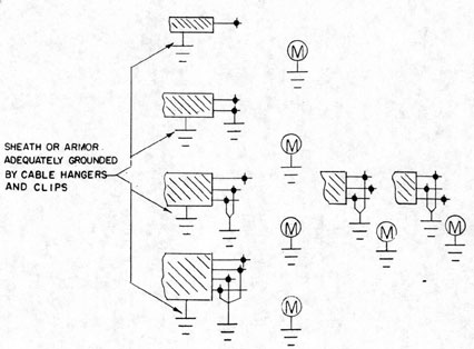
Figure 9-55 shows typical methods of measuring insulation resistance of cable circuits. The following are the minimum requirements for cables.
POWER: One megohm from each leg
or each phase lead of a circuit to ground.
I.C. and F.C.: .2 Megohms or greater for each conductor to ground (During the measurements the megger is connected from one conductor to ground; the other conductors are ungrounded and the circuit de-energized by operation of the supply switch at the power source).
9-93
FIGURE 9-55
TYPICAL METHODS OF MEASURING INSULATION
RESISTANCE OF CABLE CIRCUIT
9-94
7. SPECIAL CABLE CONSIDERATIONS.
When coaxial cable transmission lines
are passed through a W. T. bulkhead
through a gland which exerts considerable pressure on the cable, after it is
adjusted for maximum watertight security, the pressure deforms the cable and
changes the spacing between the inner
and outer conductors of the cable, thus
altering the electrical characteristics
of the line. This problem has become
very serious in submarine applications
where stuffing tubes must be pressure-proof.
TTRSA cable can be utilized to save
drilling operations, space and fittings
when several coaxial cables leave an
equipment and must pass through a bulkhead.
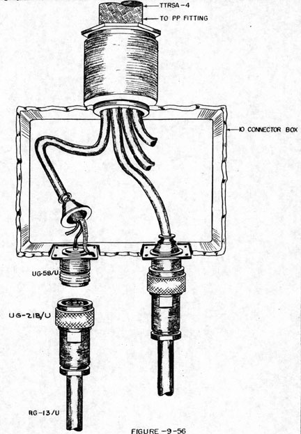
Figure 9-56 shows the method of utilizing TTRSA cable to carry coax loads
through pressure-proof fittings. The
coax feeds from the equipment to a 10
connector box, where a connection is
made to the TTRSA cable.
The TTRSA is then run through all the
pressure-proof fittings and terminates
in another 10 connector box, where
connection to equipment is made through
coax. For this application it is important that one lead be left floating to
insure constant impedance with frequency. Maintain continuity of the inner
shields in the junction boxes.
TTRSA cable has a characteristic
impedance of approximately 76 ohms.
It has been used in this application in
lengths up to 30 feet, with no appreciable
attenuation in signal. Some applications
are 60 mc IF, sync. signals, trans.
pulse, video, etc.
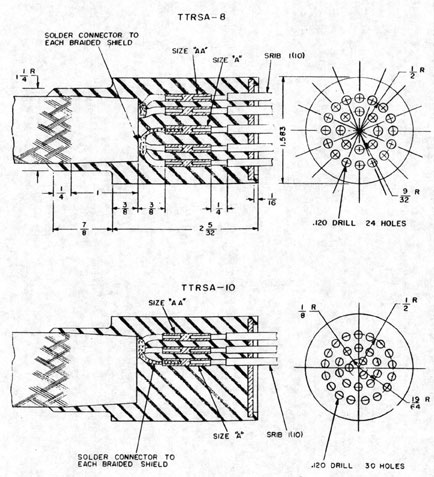
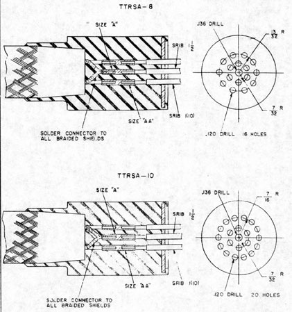
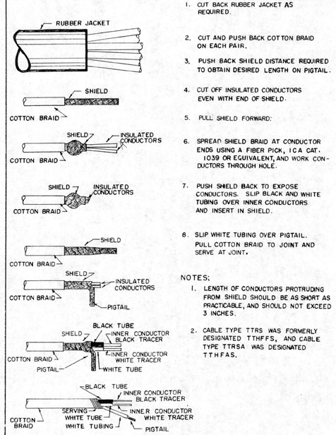
Figure 9-57 shows an approved method
of finishing ends of shielded pairs of
TTRSA cables.
Installation workers experienced difficulty in soldering a ground lead to the
shield. The insulation was easily
damaged by the application of heat. This
method involves no soldered connections
and eliminates the danger from heat.
9-95
FIGURE 9-56
COAXIAL LINE - TTRSA COUPLER
9-96
FIGURE 9-57
NAVY TYPE TTRS AND TTRSA CABLES-METHOD
OF FINISHING ENDS OF SHIELDED PAIRS