All ships cables are identified by metal
tags that show the source, relative importance and classification of each cable.
Permanently installed ship's cables are
tagged as close as practicable to each
point of connection, on both sides of
decks, bulkheads, and other barriers.
The length of cable between cable tags
should not exceed 50 feet. Non-vital
cables less than 50 feet long and located
wholly within the same compartment, so
that they may be easily traced, need not
be tagged.
2. IDENTIFICATION OF CABLES.
C
- I. C. leads
F
- Ship's service lighting feeders and general power feeders.
FB
- Battle power feeders.
G
- Fire control circuits.
R
- Electronic (radio, radar, and sonar) circuits.
XFE
- Emergency lighting and emergency power feeders.
Feeders that supply power to electronic equipment are identified as is specified for power and lighting circuits, up
to the last distribution point preceding
the electronic equipment. Then the electronic designations are used on cables
from this last distribution point to the
electronic loads. Power cables between
units of electronic equipment have electronic designations.
3. ELECTRONIC CABLE DESIGNATIONS.
Electronic cables are marked as
follows:
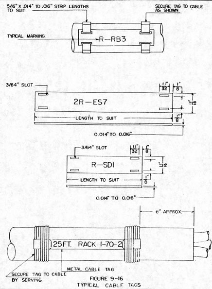
EXAMPLE: R-RB3
R
indicates electronics.
RB
indicates an entertainment receiver circuit.
3
indicates cable number 3 of the entertainment receiver circuit.
EXAMPLE: 2R-ES7
2
indicates the second surface search radar circuit on the vessel.
R
indicates electronics.
ES
indicates a surface search radar circuit.
7
indicates cable number 7 of the surface search radar. Note that where 2 or more systems with identical circuit letters are installed, the cable designation is preceded by a number.
3. COLOR BANDING.
All vital and semi-vital electronic
cables, except branch and sub-branch
circuits, have identification tags colored
as follows:
Radio, Radar, Sonar
Vital -
Red
Semi-Vital -
Yellow
Non-vital -
Gray
9-40
Cables having power system designations are color-banded red when supplying vital I.C. and F.C. circuits and
yellow when supplying semi-vital circuits.
5. DEFINITIONS.
VITAL CABLES. -Those, which if cut
in action, would disable apparatus absolutely necessary to the fighting effectiveness of the ship.
SEMI-VITAL CABLES. -Those which,
if cut in action, would disable apparatus
that contributes to the fighting effectiveness of the ship but is not absolutely
necessary.
NON-VITAL CABLES. - Those which
furnish power to apparatus whose loss
would not seriously impair the fighting
effectiveness of the ship.
6. CLASSIFICATION.
The following classification lists vital,
semi-vital and non-vital electronic, I. C.
and F.C. circuits with their circuit
letter designations. (See Table 9-3a,
9-3b and 9-3c.
For power circuits, the classifications
are shown on the feeder lists. For I. C.
and F. C. circuits; the classifications are
indicated by a note on the respective isometric wiring diagrams.
7. TAGS.
The tags for marking cable are made
of colored soft steel, zinc, or aluminum
tape.
Figure 9-16 shows dimensions, shape
and installation.
8. CONDUCTOR MARKING.
All active conductors of electronic
cables are marked by stamping, or by
use of branded synthetic sleeving, where
terminals are too small to be stamped.
Terminals to be inter-connected should
be marked identically.
In addition to its own identifying marker.
each conductor is marked with the cable
designation of which it is a part. This
is done by placing a synthetic sleeve or
fiber tag, having the cable designation
on the conductor, next to the point where
the connection is made within a connection box. Spare conductors of each cable
are grouped and identified with their
cable designations.
Color coding for individual conductors
is shown in Tables 9-4 and 9-5.
9-41
CIRCUIT LETTERS
VITAL (RED)
CIRCUIT LETTERS
NON-VITAL (GRAY)
Radio Communication
R -RA
Radio Transmitting and Receiving Antenna Systems (includes R. F. extension system)
R-RB
Radio Entertained Receiver Circuits (includes both audio and radio frequency distribution circuits)
IR -RC
Transmitter remote control system circuits (also combined transmitter and receiver control circuits)
2R-RC
Receiver remote control system circuits
3R-RC
Teletype circuits
R-RR
Cables between units of a receiving equipment
R-RT
Cables between units of a transmitting equipment
Countermeasures
R-CC
Communication countermeasures systems
(R-C)
R-CR
Radar countermeasures systems
R-CS
Sonar countermeasures systems
TABLE 9-3a
ELECTRONIC SYSTEMS
9-42
CIRCUIT LETTERS
VITAL (RED)
CIRCUIT LETTERS
NON-VITAL (GRAY)
Beacons
R-BA
Aircraft Beacon Systems
(R-B)
R-BC
Radio Beacon Systems
R-BR
Radar Beacon Systems
R-BS
Sonar Beacon Systems
R-BN
Nancy Beacon Systems
Sonar (R-S)
R-SA
Azimuth Echo-Ranging-listening systems
R-SE
Depth Charge Direction indicators and range estimators
R-SD
Depth Determining Sonar Systems
R-SM
Sonar Monitoring Circuits
R-SK
Scanning Sonar Systems
R-SP
Attack Aid and Auxiliary Systems
R-SL
Sonar Listening Systems
R-SR
Remote Indicator Systems
R-SO
Bathythermograph Systems
R-SU
Underwater Object Locator Systems
R-SQ
Combination Depth (Azimuth Sonar Systems)
R-SS
Sounding (Fathometer) Systems
Search
R-SB
Underwater Telephone Systems
Radar System
R-EA
Air Search Radar Circuits
(R-E)
R-EC
CCA System Circuits
R-EF
Fighter Director Radar Circuits
R-ER
Radar Repeater Circuits
R-ES
Surface Search Radar Circuits
R-EW
AEW System Circuits
R-EZ
Zenith Search Radar Cts.
TABLE 9-3b
ELECTRONIC SYSTEMS
9-43
CIRCUIT LETTERS
VITAL (RED)
CIRCUIT LETTERS
NON-VITAL (GRAY)
Fire Control Radar
R-FB
Guided Missile Fire Control Radar
Systems
R-FG
Heavy Machine Gun Battery Fire Control Radar Circuits
(R-F)
R-FM
Main Battery Fire Control Radar Circuits (6" Guns and Larger)
R-FS
Double Purpose Battery Fire Control Radar Circuits
IFF
R-IA
Circuits of IFF Equipment Operating in conjunction with Air Search Radar Systems
(R-I)
R-IC
Circuits of Integrated IFF System
R-ID
Circuits of IFF Equipment Operating in conjunction with Fighter Director Radar Systems
R-IF
Circuits of IFF Equipment Operating in conjunction with Radar Repeater Systems
R -IR
Circuits of IFF Equipment Operating in conjunction with Radar Repeater System
R-IS
Circuits of IFF Equipment operating in conjunction with surface Search Radar Systems
R-IT
IFF Transponder Circuits
TABLE 9-3c
ELECTRONIC SYSTEMS
9-44
VITAL CIRCUITS (Light Blue)
G
General alarm and chemical attack system
GA
Torpedo control systems
GE and GEP
Main battery control systems
GH and GHP
Anti-aircraft control systems
GM
Machine gun control systems
GJ and GSP
Secondary battery control systems
GT
Captain's target designation system
JA
Primary battle telephone system
LC
Gyro compass system
1LG, 2LG, 3LG and 4LG
Gyro stabilizer motor generators
5LG
Angle gyro system
1MC to 5MC 11MC to 17MC
General and battle announcing systems (where circuit G is incorporated in MC system)
SEMI-VITAL (Green)
EP
Telephone and voice tube call bell system (protected calls)
IEC and 2EC
Lubricating oil low pressure alarm systems
K
Shaft revolution indicator system
L
Steering telegraph system
NON-VITAL (Green) Cont'd.
1MB and 2MB
Engine order telegraph systems
1MC to 6MC
General and battle announcing systems where circuit G is not incorporated in MC systems
21 MC and Similar Systems
Intercommunicating type announcing system
N
Rudder angle indicator system
1PA to 5PA
Auxiliary gun firing systems
PR
Plotting room ready light system
QB
Shell hoist latch indicator system
QC
Powder hoist interlock system
R
Ready light system
RA
Intra turret emergency alarm system
RE
Turret power elevating indicator system
RT
Turret power training indicator system
1U to 5U
Cease firing signal systems
IVB to 5VB
Solar signal systems
XJ
Supplementary telephone system
XGE
Auxiliary main battery control
XJA
Auxiliary battle telephone system
XL
Auxiliary steering telegraph system
X1MB and X2MB
Auxiliary engine order telegraph system
XN
Auxiliary rudder angle indicator system
Y
Underwater log system
TABLE 9-3d
INTERIOR COMMUNICATION AND FIRE CONTROL SYSTEMS
9-45
FIGURE 9-16
TYPICAL CABLE TAGS
19-46
COLOR IDENTIFICATIONS
Power System
Cable Type
Phase or Polarity
Color or Code
3 ph. a.c.
3 cond.
A B C
Black White Red
2 cond.
AB
A = Black B = White
BC
B = White C = Black
AC
A = Black C = White
3 ph. d.c.
3 cond.
+ ± -
Black White Red
2 cond.
+ and ±
+ Black + White
± and -
± White - Black
+ and -
+ Black - White
2-wire d.c.
2 cond.
+ -
Black White
Note 1. - The conductor to be used as the ground conductor, in
cables where this is required, in any system, shall be the red conductor in 3-conductor cables and the green conductor in 4-conductor cables.
Note 2. - The ±, or neutral, polarity, when it exists, shall always be identified by the white conductor. This white conductor shall always be connected to the screw shell of lighting unit sockets to reduce to a minimum the shock hazard to personnel.
9-47
COLOR CODE USED IN MARINE ELECTRICAL I. C. and F. C. CABLES NAVY TYPE
Wire No.
Base Color
Tracer Color
Tracer Color
1
Black
2
White
3
Red
4
Green
5
Orange
6
Blue
7
White
Black
8
Red
Black
9
Green
Black
10
Orange
Black
11
Blue
Black
12
Black
White
13
Red
White
14
Green
White
15
Blue
White
16
Black
Red
17
White
Red
18
Orange
Red
19
Blue
Red
20
Red
Green
21
Orange
Green
22
Black
White
23
White
Black
Red
24
Red
Black
White
25
Green
Black
White
26
Orange
Black
White
27
Blue
Black
White
28
Black
Red
Green
29
White
Red
Green
30
Red
Black
Green
31
Green
Black
Orange
32
Orange
Black
Green
33
Blue
White
Orange
34
Black
White
Orange
35
White
Red
Orange
36
Orange
White
Blue
37
White
Red
Blue
38
Brown
39
Brown
Black
40
Brown
White
41
Brown
Red
42
Brown
Green
43
Brown
Orange
44
Brown
Blue
TABLE 9-5
NAVY STANDARD COLOR CODE FOR CONDUCTORS
9-48
SECTION 6
PREPARING FOR INSTALLATION
1. INTRODUCTION.
The cable for a piece of equipment has been installed in the wireways and is run to the equipment. The job now is to tie it into the equipment. Assume that the cable is to enter the equipment through a stuffing tube. The first consideration is the proper length of cable; it should be made somewhat longer than just enough to reach the connection point.
Form the cable run from the last cable strap to the equipment by hand, allowing for a clean sweep and enough slack at the stuffing tube. This last allowance is for the conductor run inside the equipment; here, good judgment must be used. Determine whether the conductor goes directly to its connection or whether it forms a laced cable and breaks off. Determine the longest conductor run in the laced cable, and add approximately 2 1/2 times this length to the length already determined up to the stuffing tube. This safety factor covers mistakes in attaching lugs or allows for re-routing. It is desirable to have a surplus so as to avoid cable renewals in the event of repairs. In applications where trouble may be anticipated, as in outside submarine wiring, allow approximately four feet additional slack in the cable run to avoid cable renewals, especially where the cable run is long. The cable length is now known and cut. The next step is to remove the armor.
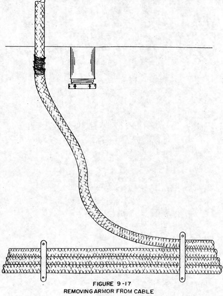
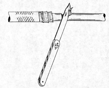
2. REMOVING THE ARMOR.
Form the cable as it is to be run into the stuffing tube and carefully estimate where the cable should come through the tube. Mark this position with a piece of friction tape. (Figure 9-17). The tape serves to seize the armor to prevent unraveling and holds down the armor while cutting; in addition, it serves a marker.
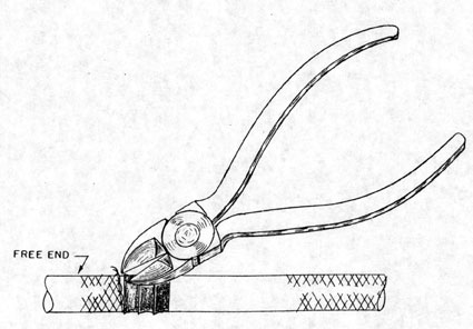
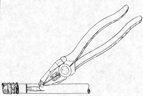
The actual cutting of the armor may be done with diagonal cutters or with armor strippers. Strippers, when available, are capable of doing a neat, fast job (See tool section), although care must be used in working knife blade adjustments on these tools. Most installation men use diagonal cutters. The quality of the work done with diagonal cutters depends, to a great extent, upon experience; an in-experienced man may easily cut through insulation and spoil a cable.
Method of cutting armor is as follows:
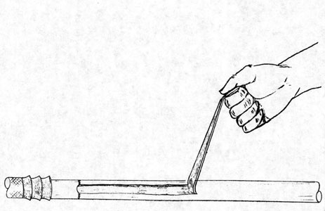
The cut may be taken either just in front of the tape marker or within it. By cutting just in front of the marker, the worker can closely watch his cut and avoid cutting insulation. The frayed edges of the armor can then be trimmed away. When cutting within the tape marker, the tape serves to hold the frayed edges down, but care must be used to avoid cutting the insulation. The armor is cut around the circumference of the cable (Figure 9-18).
9-49
When the length of armor to be removed is not too great, it may be worked off without further cutting, but in some cases the armor must be cut lengthwise
for easy removal. The important thing to remember in cutting the armor is to avoid cutting the insulation, since this may let the frayed armor edges penetrate the cable and cause grounding.
9-50
FIGURE 9-17
REMOVING ARMOR FROM CABLE
9-51
FIGURE 9-18
REMOVING ARMOR FROM CABLE
19-52
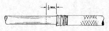
3. STRIPPING INSULATION.
After the armor has been removed, start to remove the insulation at a distance of approximately 1/2 inch from where the armor terminates (Figure 9-19).
The following procedure is recommended in stripping the insulation:
First, if one end of the cable is not secured, place the end in a vise or have another man hold the cable. Put a bend in the cable and carefully ring the insulation (Figure 9-20) taking care to cut only the insulating jacket and not into the insulation of individual conductors. With the knife blade at an angle, start cutting a strip lengthwise, approximately 1/2 inch wide and long enough to allow side cutters a grip on the insulation (Figure
9-21 and 9-22). Pull down on the cut with the side cutters. This will form a 1/2 inch strip, and after stripping approximately 4 inches, the remainder of the strip can usually be removed by hand (Figure 9-23).. It is an easy matter to peel off the remaining insulating jacket and to trim off the filler and threads of insulation with a pair of scissors or diagonal cutters.
The Jones cable stripper may be used to perform all of these operations very efficiently. Detailed instructions on the use of this stripper are included in chapter 3 - Hand Tools. The Huff cable stripper (See Chapter 3) can be used only on lengthwise cuts.