255. Chapter I gave a general description of three main types of ships. This
chapter deals, in more detail, with the methods employed in directing the guns
on to the target and firing the guns.
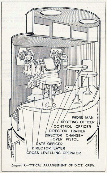
The guns are directed and fired from a DIRECTOR SIGHT (see Diagram 9a),
mounted in the DIRECTOR CONTROL TOWER which is situated in the after
end of the bridge. This contains the Director Sight in the fore part, the Rangefinder is underneath the Director Sight, and the Control Team is in the rear (see
Diagram 9). The position of the rangefinder is shown in Diagram 20.
REASONS FOR A DIRECTOR SYSTEM.
256. Before describing a Director Sight in detail it is useful to consider why
this method of firing is used.
The disadvantages of laying, training and firing the gun from the gun itself may
be briefly summarised as follows:-
(i) It is difficult to point out a target to several gunlayers simultaneously.
(ii) The guns, being comparatively low down near the water-line, do not get
a very good view of distant targets.
(iii) Being low down near the water-line the telescopes of the gun-sights are
liable to be clouded by spray.
(iv) Each gunlayer has his own individual error, and though these errors
may be small, they accumulate and cause the shots of a salvo to fall
some considerable distance apart from each other.
(v) It is most unlikely that all the gunlayers in the ship will fire at the same
instant; as a result there may be an appreciable period during which
one or more guns will be firing and making noise and smoke.
(vi) As all the guns are more or less on the same level, the smoke from some
guns is bound to cause interference in the laying of other guns.
(vii) Spotting the fall of shot from a number of guns fired one after the other
is extremely difficult.
257. To overcome these disadvantages, the director system is used. In this
system one sight only is aimed at the target and arrangements are made so that
when the telescope of this sight is on the target, all the guns arc at the correct
angles of elevation and training to hit the target. Arrangements are also made
so that the man looking through this one director telescope can fire all the guns
at the same instant when his telescope is aimed at the enemy.
258. The reasons for having a director system are as follows:-
(i) The target has to be indicated to one man only. This is a much easier and
quicker task than getting many gunlayers on the target.
(ii) As the sight need not be at the guns it can be placed high up on the
bridge, where its user can obtain a far better view of distant objects.
(iii) Being high up the director telescopes are clear of spray.
83
(iv) The errors of the individual layers do not prevail to the same extent;
the error of the layer of the one sight will affect all guns alike so that the
shells will all fall close together; but such a layer, being specially picked,
can be trained to a higher degree of skill. This makes the observation
and control of fire easier and increases the hitting power of a broadside.
(v) As all guns are fired at the same instant, the shots of a salvo will all fall
at the same time; this makes observation of the fall of shot easier for
the control officer. Also, the period of noise and disturbance is over
quickly and longer periods of quiet are available for rangetaking and
control orders, etc.
(vi) The sight can be placed so high that little or no interference is caused
by smoke from the guns.
(vii) Blind fire can be carried out
ALLOWANCES TO BE MADE IN DIRECTOR FIRING FOR
ELEVATION AND FOR TRAINING.
259. In a system of firing where the sight, situated high up in the ship, has to
transmit electrically both elevation and training, through a FIRE CONTROL
TABLE, to guns which are lower down and also widely separated along the
length of the ship, it is fairly obvious that certain allowances must be made if all
the shells from a broadside fired together are to fall in one place.
These allowances may be summarised as follows:-
For Elevation
Dip.
Differences in muzzle velocity of each gun.
Tilt.
Displacement.
For Training
Convergence.
Drift.
For Elevation.
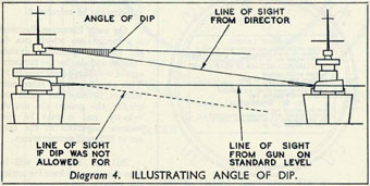
Dip. (Diagram 4.)
260. Dip is the correction to elevation necessary because the Director Sight
is mounted considerably higher than the mean level of the guns. It is also an
allowance that is sometimes made at individual guns, which are some distance
higher or lower than the mean level of the guns. This mean level is known
as the STANDARD LEVEL.
Diagram 4 is an illustration which shows the angle of dip from the Director
to the standard level, which has to be allowed for. In this picture the guns are
D
84
not elevated for the range of the target, and the ship is shown upright in order
to make the diagram more simple.
It will be noticed that the line of sight from the Director to the target dips
downwards compared with the line of sight from the gun. If no allowance was
made for the angle of dip, the guns would be depressed by that amount and
consequently, when range was applied and all the guns were elevated, they would
be below the correct elevation, by an amount equal to this angle.
261. The size of the angle depends upon the range. At short ranges it is large,
and becomes smaller as the range increases. It also depends upon the height of
the Director above the Standard Level.
In all modern Fire Control Systems this allowance is made in the FIRE
CONTROL TABLE, and the corrected elevation is sent electrically to the guns.
When it is necessary to correct a single gun or turret, because of its distance
above or below the Standard Level, this allowance is made mechanically in the
ELEVATION RECEIVER at that particular gun. This moves the mechanical
pointer at the receiver, so that
the gunlayer, in re-aligning his
mechanical pointer with the
electrical pointer, moves the gun
through the required angle.
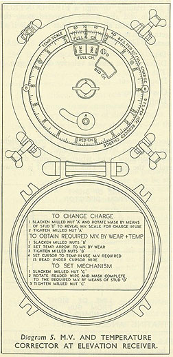
Differences in Muzzle Velocity
and Temperature of the Charge
at each Gun. (Diagram 5.)
262. Every time a gun is
fired the hot gases generated by
the cordite charge and the rapid
movement of the shell down the
bore, wear away the surface of
the gun tube. This wear is slight
but after a large number of
shells have been fired it has an
appreciable effect on the velocity
with which the shells leave the
muzzle. It can, however, be
measured and the loss of muzzle
velocity can be calculated.
On each Elevation Receiver
is a mechanism which can be
set for the calculated muzzle
velocity and also for the temperature of the charge (see Diagram 5).
This also has to be taken into
account, because the hotter the
cordite, the greater the muzzle
velocity, and it may be that
various magazines in the ship
are at different temperatures.
263. In Diagram 5 will be
seen the arrangements for setting
the muzzle velocity and temperature. The instructions for
setting the mechanism are given
85
inside the cover-plate and the settings should always be checked by the gunlayer,
on closing up at the gun.
The effect of moving the corrector is to move the mechanical pointer in the
receiver, which, when re-aligned with the electrical pointer, will give the corrected elevation to the gun. Range also affects the mechanism because the
correction to elevation necessary for a given loss of muzzle velocity or temperature
varies with the range.
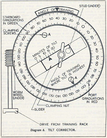
Tilt. (Diagram 6.)
264. The guns and' director all rest and train round on roller paths fixed to
the
ship. When the ship is built the planes of these roller paths are fixed as nearly
86
as-possible parallel with one another, so that if a spirit level were placed on each
in turn, both fore-and-aft and athwartships, the bubble ought to be central in
each case. Unfortunately slight differences among the roller paths are always
bound to occur, causing each roller path to be tilted slightly, like a plate which
has something underneath one side. Unless this error of tilt is allowed for, the
guns will not have the same elevation above the deck. A gun, mounted on a
roller path, which is tilted up away from the enemy would shoot over and vice
versa.
The amount and direction in which each roller path is tilted is measured and
calculated when a tilt test is carried out in dock. The result of this test is applied
to a tilt corrector.
265. A tilt corrector is fitted at each director and in the Elevation Receiver
of each gun (see Diagram 6). It consists of a worm-wheel with bearing ring which
is driven in training at the same speed as the gun or director. The bearing ring is
graduated from 0° to 180° red and green and reads, against a fixed index, the
bearing of the gun or director. Frictionally connected to the inside of the
ring is a slotted plate normally secured by two clamping screws "A." An
arrow engraved on the plate is set to the bearing at which tilt is highest.
A sliding block is fitted in the slot and can be clamped by means of a butterfly
nut so that the arrow on the block reads the tilt in minutes against the scale on
the plate. Formed on the rear side of the sliding block is a stud which is in the
centre of the plate when the tilt is set to zero minutes. As the bearing ring and
plate rotate with the stud in this position no cranking movement can take place
and hence no movement for tilt is imparted to the receiver pointer, but when the
sliding block is set to a number of minutes the stud will be moved to the right,
off centre of the plate, so giving a cranking movement as the bearing ring and plate
rotate. This cranking movement is imparted to the mechanical pointer of the
receiver and when the gunlayer re-aligns his pointers the necessary correction to
elevation is given to the gun on its new bearing.
The amount and direction of the tilt are set on the corrector by the ordnance
artificer and must not be altered. The gunlayer, however, must ensure when lining
up, and subsequently, that the bearing ring reads against the index the same
bearing as that to which the mounting is trained.
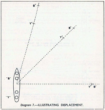
Displacement. (Diagram 7.)
266. When firing on the beam all the guns are approximately the same
distance from the enemy but when firing fine on the bow, all guns will be at a
different distance from the enemy and will therefore require slightly different
elevations. An elevation correction is therefore made to each gun corresponding
to its distance from a selected point in the ship. The distance of each gun from
this point is called its displacement. The small difference in elevation required
by each gun depends on its displacement and also the bearing of the enemy. The
allowance is made by including the necessary correction on the tilt corrector.
We now have two allowances set on the tilt corrector and to identify what
settings we require, we call them either testing tilt or firing tilt. Testing tilt
only allows for tilt and is used when carrying out a director test. Firing tilt combines tilt and displacement and is always used for firings.
For Training.
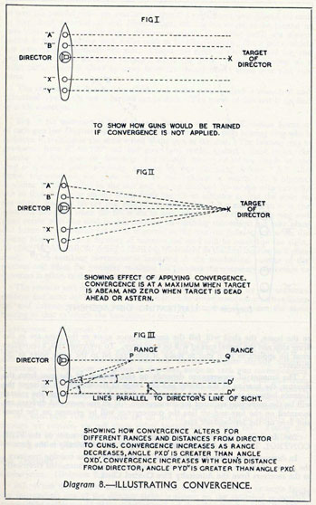
Convergence. (Diagram 8.)
267. When the director is trained on to the target, the bearing or angle from
the fore-and-aft line of the director sight, is shown on the electrical pointer in
the training receiver. If all guns follow and get their black pointers in line, they
will be trained on the same bearing or angle from the fore-and-aft line and will
therefore shoot on parallel lines (see Diagram 8). This means that when firing
87
on the beam, the shell will fall the same distance apart as the guns are in the
firing ship and the lateral spread will be very large. To overcome this, a correction
must be applied to each gun to make it converge on to the same point as the
director.
The amount of convergence depends on the distance of the gun from the
director, the bearing of the enemy and the range of the enemy. The larger the
distance between the gun and the director and the shorter the range, the greater
will be the correction required for convergence. If all the guns and director are
mounted on the fore-and-aft line the convergence will be greatest on the beam
and zero on the fore-and-aft line.
268. In modern Fire Control Systems this correction is made in the FIRE
CONTROL TABLE and the corrected training is sent electrically to the guns.
In destroyers the correction is applied automatically at the training receivers;
the range, which affects the amount of convergence, being transmitted electrically
to the receivers from the Admiralty Fire Control Clock.
Drift.
269. Owing to the right-handed spin given to the shell by the rifling of the gun,
the shell wanders to the right as it flies through the air. This wander has to be
88
89
allowed for if the shell is going to hit the enemy, but the amount of wander can
be measured during experimental firings for all guns and types of shell, and a
mechanism can be constructed to allow for it. The amount of wander due to
DRIFT depends, of course, upon the range, which is related to the time that the
shell is flying through the air.
The allowance for drift is not confined to the Director System of firing,
because all shells are affected, whether they are fired locally at the gun or by the
Director.
In Director Firing the allowance is made in the Admiralty Fire Control Table
and the corrected training is sent to the guns electrically.
Summary of Corrections When Firing by Director.
270.
(a) Corrections to Elevation.
DIP
Allowed for in the Admiralty Fire Control Table.
DIFFERENCES IN MUZZLE VELOCITY AND CHARGE TEMPERATURE AT EACH GUN.
Allowed for by Corrector Mechanism at each ELEVATION RECEIVER.
TILT
Allowed for by Corrector Mechanism at each ELEVATION RECEIVER.
DISPLACEMENT
Included in the TILT Correction.
(b) Corrections to Training.
CONVERGENCE
Allowed for in the Admiralty Fire Control Table or at TRAINING RECEIVERS in Destroyers and some other ships.
DRIFT
Allowed for in the Admiralty Fire Control Table.
Provided that efficient lubrication is religiously
carried out (para 130)
90
91
THE DIRECTOR SIGHT. Diagrams 9 and 9a.
271. Having considered the various reasons for using the Director System
and the allowances to be made when firing by DIRECTOR, let us consider the
sight itself.
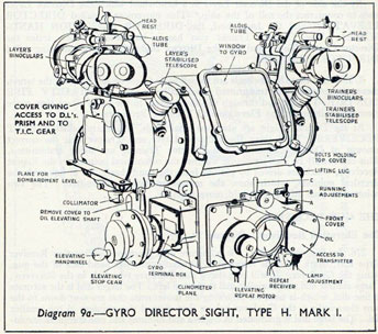
Diagram 9a is an illustration of a typical Director Sight. As we have already
seen, this sight is situated in the foremost part of the DIRECTOR CONTROL
TOWER and has as its crew a DIRECTOR LAYER and a DIRECTOR
TRAINER.
It will be noticed that both the Director Layer and Trainer have a telescope
and a pair of binoculars through which to look. The telescopes are STABILISED;
that is to say a prism inside them is kept upright by a fast driven Gyro, with the
result that the Director Layer and Trainer can always see the target through the
telescope, even when the ship is rolling. The telescopes are called the STABILISED TELESCOPES and are always used, as long as the Gyro is operating
correctly. The BINOCULARS are fixed to the mounting of the Director Sight
and therefore move with it. These are called UNSTABILISED.
272. The Gyro, which is housed in between the two stabilised telescopes, besides
keeping the prisms upright in the telescopes, has an attachment, which will fire
the guns automatically at the correct moment if the TRIGGER, which is beside
the DIRECTOR LAYER, is kept pressed. This trigger has two positions
and can be turned so that the guns can either be fired by the Gyro, called GYRO
FIRING or by the Director Layer looking through his unstabilised binoculars
and firing when he is on the target, in which case it is called DIRECTOR FIRING.
The firing can be done either by pressing the trigger itself or by pressing a foot
pedal. The trigger is not shown in Diagram 9a but can be seen in Diagram 9.
92
The "P" Sight.
273. The difference which at once distinguishes the power director or type
"P" sight from any other gyro-stabilised sight previously mentioned, is that
whereas in the latter, the gyro stabilises a part of the optical system only, in the
"P" sight, a powerful oil motor controlled by the gyro stabilises the whole
elevating part of the sight, including the brackets which hold the binoculars.
By this means the gyro itself is freed from all the external influences which
affect it when it stabilises a prism, as in the previous sights.
This sight can also be used against an aircraft target. The Layer and Trainer
each have one pair of binoculars which have greatly improved optical qualities
for night-use instead of a stabilised telescope and a pair of unstabilised binoculars
as in previous sights.
The stabilisation of the sight can also be relayed to outside instruments in
the Director Control Tower, such as the Control Officer's binoculars and the
inclinometer, so that they too are kept on the target when the ship is rolling.
The stabilised line of sight can be elevated or depressed relative to the horizon
by the SIGHT ELEVATION ADJUSTMENT. This is used for getting on to
the target or for forecasting when necessary.
274. The FIRING SWITCH, which closes the firing circuits and so fires
the guns, is mechanically operated at the correct instant when the sight is to
STABILISED and GYRO firing is used. It is operated by the Director Layer
when DIRECTOR firing is used. The switch is put either to GYRO or
DIRECTOR by the Director Layer.
The sight is put to STABILISED or DIRECTOR by the Layer.
By the side of the Director Layer is a handwheel which the Director Layer
uses to counteract the roll of the ship. This movement is called DIRECTOR
ELEVATION and the handwheel, the DIRECTOR ELEVATION HANDWHEEL. The Director Trainer also has a handwheel, which trains the
Director Control Tower and also the Director Sight, the movement being called
DIRECTOR TRAINING.
275. When these handwheels are turned so as to get on and keep on the target,
these movements are transmitted electrically to the ADMIRALTY FIRE
CONTROL TABLE and through this instrument, to the guns, where they move
electrical pointers at the Elevation and Training Receivers.
At the Director Sight are also two small dials, which are called REPEAT
RECEIVERS. They show the Director Layer and Trainer that the correct
amount of Director Elevation and Director Training are being transmitted.
This can readily be seen by noting whether the mechanical pointers in the Repeat
Receivers, which are driven by pinions from the handwheels, are in line with the
electrical pointers, which show the movement being transmitted. The two
pointers in each Receiver should move together.
THE GUN RECEIVERS.
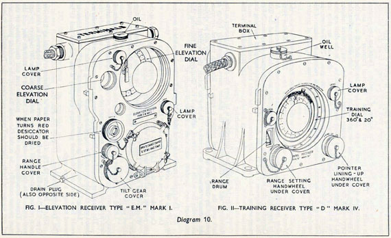
The Elevation Receiver. Diagram 10, Fig. I.
276. In Diagram 10, Fig. I is a picture of a Destroyer's Elevation Receiver
Type EM, Mark I. This Receiver is situated at the left hand side of the gun,
facing the Gunlayer. It will be noticed that there are two dials in the Receiver;
a large central dial and a smaller dial to the top left. The larger dial is the accurate
or fine dial, which is used for following the movements that are sent down to the
guns electrically; the Gunlayer having first aligned the pointers in the smaller
dial. The large dial is graduated in degrees and minutes and one complete
93
94
revolution equals 5 degrees of elevation; the Mark III Receiver of this type provides
that one revolution equals 10 degrees, each small graduation being three minutes.
The smaller or coarse dial is for degrees of elevation. There are two pointers
in each dial. The red pointers are known as "Electrical Pointers" and are the
pointers that are moved both by the Director Layer hunting the roll and by the
Transmitting Station applying changes in the range, which directly affect the
elevation of the gun. The movements therefore, of these red pointers indicate
to the Gunlayer the elevation at which his gun should be. On the dials are also
two white pointers called the "Mechanical Pointers"; that is to say they are
driven mechanically from the elevating arc of the gun. The Gunlayer, in
following the electrical pointers with the mechanical pointers by means of his
handwheel has elevated the gun to the correct angle when both pairs of pointers
are brought in line.
277. Behind a hinged cover-plate at the Elevation Receiver will be seen the
Muzzle Velocity and Temperature Corrector (see para. 262 and Diagram 5) to
allow for differences in muzzle velocity and the temperatures of the charge. At
the lower left hand corner is a screwed cover-plate under which is found the Tilt
Corrector; this is adjusted to allow for Tilt and Displacement (see paras. 264 to
266 and Diagrams 6 and 7). Just above this is another cover-plate enclosing the
range-setting handle for the dip correction, the scale being read through a small
circular window. Normally the range for dip correction is transmitted to the
receivers electrically from the Transmitting Station.
The effect of setting these corrections is to move the mechanical pointer in the
Receiver; and the Gunlayer, seeing the pointer move, immediately brings it
back until the white mechanical pointer is again in line with the red electrical
pointer. By doing this he alters the elevation of the gun slightly and so applies
the necessary correction to elevation. During an action, the electrical pointers
are moving the whole time between salvos and the Gunlayers are following this
movement very carefully with their mechanical pointers.
278. This type of receiver is used with "Magslip" transmission which requires
no "lining up". (see para. 290.)
On other types of receiver there is a " LINING UP " knob.
Cards showing the "LINING UP" settings are prepared and placed at the
gun position in all ships not fitted with " Magslip " transmission.
Whenever the order "Line Up" is received at the guns, the Gunlayers align
their electrical pointers, by means of the lining up knob, to the lining up setting
shown on the card.
"Lining up" is done with no current in the electrical circuits and when all
positions have reported "Lined up", the circuits are closed and all receiver
electrical pointers are in their correct positions.
The Gunlayer should note that the pointers do not jump when the circuits are
closed and that the correct bearing of his gun is showing on the Tilt Corrector.
"Lining Up" can also be carried out with current "On". This, however,
would be a slow and laborious procedure, especially if the pointers had to be
moved through a large angle.
The Training Receiver. Diagram 10, Fig. II.
279. In Diagram 10, Fig. II, is a picture of a Destroyer's Training Receiver
Type "D," Mark IV. In this Receiver there is only one dial, engraved so that the
inner portion is showing 20 degrees and the outer portion 360 degrees for one
revolution. It is the inner scale, therefore, which is the accurate one, and the
Gun Trainer accordingly aligns the outer pointers first and then follows up the
inner pointer carefully. As in the Elevation Receiver, the electrical pointers are
red and are moved by the Director Trainer and also by the Transmitting Station
95
sending out the necessary "Aim off" to the guns. The mechanical pointers are
white and are driven off the Training Rack at each gun, thus showing the actual
training of the gun. By following the red electrical pointers with the white
mechanical pointers the Gun Trainer points the gun in the correct direction.
280. In the Receiver there is also a range scale. The range is sent electrically
to the Receiver from the Transmitting Station, but can be set by hand, if the transmission breaks down, by means of the small range-setting handwheel. The
setting of this range is required for convergence (see paras. 267 and 268) and has
the effect of moving the mechanical pointer. The Trainer, seeing the pointers
separate, brings the mechanical pointer back in line with the electrical by means
of his training handwheel and so gives the necessary correction to the gun.
There is also a "LINING UP" knob in the Receiver for initially lining up the
red electrical pointers with the red crosses engraved on the face of the dial at zero.
This is for the same reason as in the Elevation Receiver when "Magslip" transmission is not used.
These two Receivers have been taken as typical for all classes of ships. In each
class of ship there are, of course, slight variations but the reader should have no
difficulty in recognising these differences, bearing in mind the essential requirements of the Receivers themselves.
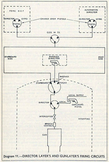
FIRING ARRANGEMENTS. Diagram 11.
281. The guns are normally fired from the DIRECTOR, but it is necessary
to provide means whereby the Gunlayer may fire them should the electric circuits
be broken by damage.
As will be seen from the previous description of a typical Director Sight, the
Director Layer has either a trigger or a foot pedal which he presses to fire the
guns electrically. This trigger can be put to either GYRO or DIRECTOR,
according to the method of firing that is going to be used. When the trigger
is pressed the circuit for firing the guns is completed up to the gun. At the gun
is a switch, called the INTERCEPTOR, which, when closed, brings the gun to
the " Ready " position for firing. Thus, when both the Interceptor and trigger
are closed, the guns will fire.
282. The firing circuits are energised from a motor generator and are led from
the Director to the Transmitting Station, through a change over switch, which
decides whether the foremost or after Director is to fire, and from the switch along
either side of the ship to the guns, so that, should one circuit get damaged, the
other can still be used. When the trigger is pressed, both circuits are energised up
to a change over switch at the gun, marked PORT and STARBOARD. From this
switch a single circuit goes to the INTERCEPTOR and from there to the electric
tube which fires the gun. Thus, with the change-over switch at the gun to PORT,
the circuits on both sides of the ship are energised up to the switch and from there
the Port circuit fires the gun, via the Interceptor. Should the gun not fire with
the remainder of the broadside, owing to Port firing circuit being damaged, the
switch is put to STARBOARD and the gun may then fire.
283. Should all the guns in the broadside not fire when the trigger is pressed,
it means that both the port and starboard firing circuits are damaged, because
half the guns have their switches to PORT and half to STARBOARD. When this
happens, it means that each Gunlayer must now fire. Alongside the Gunlayer is
another switch marked DIRECTOR and LOCAL. Normally this switch is to
DIRECTOR but when it is put to LOCAL the Gunlayer's trigger is brought into
operation and when this is pressed it completes a circuit from the Gunlayer's
trigger, through the INTERCEPTOR to the electric tube. This circuit is energised either from the main generator or from local batteries in the turret.
96
The above description gives typical arrangements for cruiser and larger ships. In destroyers there is only one firing circuit, which is led down to starboard side of the ship from the Director. There are also means by which the guns can be fired by percussion should all electrical power fail.
97
ELECTRICAL TRANSMISSION AND LINING UP.
284. So far we have seen that certain movements are sent down from the
Director Control Tower to the Transmitting Station and from the Transmitting
Station to the guns, electrically. This is a broad term for various types of electrical transmission, the efficiency of which has improved steadily as later types
of ships have been built and as the accuracy of the weapons and the controlling
instruments has increased.
The three main types of electrical transmission to be discussed here are:-
(i) Step by step.
(ii) Synchronous.
(iii) Magslip.
Each type of transmission is dealt with separately with a few words on the
advantages and disadvantages of each and how each type is lined up.
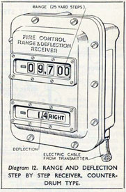
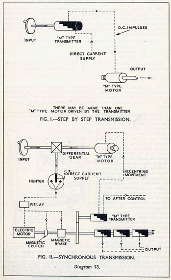
Step by Step. Diagrams 12 and 13.
285. This is the original transmission system. It is simple and cheap to make,
and is used in a variety of circuits. It has been largely superseded, but is still to
be found. Diagram 12 shows a step by step counter-drum receiver. Diagram 13,
Fig. I gives a diagrammatic representation of the principle on which the system
works.
The receiver shown in Diagram 12
is, within limits, a very reliable
instrument owing to its simplicity.
Provided the system, of which such
a receiver forms a part, is properly
lined up in the beginning, and
nothing goes wrong elsewhere in the
circuits, there can be no reasonable
doubt about the information it gives.
98
99
The principal disadvantages were:-
(i) If the transmitter moved too fast the receivers would lag behind and
get out of step.
(ii) The number of receivers that could be served efficiently by one transmitter was limited.
(iii) There could be no change over from one transmitter to another (e.g.,
from one Director to another) unless both transmitters were in line,
each with the other.
(iv) Certain faults which might develop in one receiver might throw the whole
system out of gear by mutual interference.
Lining Up.
286. From the above it will be seen that lining up, that is to say making the
Receiver and Transmitter show the same reading, is very important.
If no lining-up knob is fitted, the instruments are run from one limit to the
other and back again and then brought to a pre-arranged position, the power
being kept on the whole time.
If a lining-up knob is fitted the Receivers are brought to the lining-up setting
with power off. The circuits are then closed. When the circuits are closed it is
important to watch the Receivers very carefully to see that they do not jump a
step. If they do, either because they have been lined up badly or owing to an
electrical fault, one should re-align them if one can. If not, the amount they have
jumped should be reported.
Synchronous. Diagram 13, Fig. II.
287. This system was adopted in 1922 for use in Director Systems, to replace
Step by Step in certain systems, and is found in "Nelson" class and earlier
battleships when modernised and 8-in. and early 6-in. cruisers of new construction.
In this system a HUNTER controls the relay switch supplying power to an
ELECTRIC MOTOR, which has enough mechanical power to drive a number
of "M" Type Motor transmitters to outlying positions, which require a stronger
drive than could be given by a simple "M" Type transmitter. The system is
energised electrically from a direct current supply.
The Hunter is turned one way or the other by the mechanical input, for instance,
the Director Trainer's handwheel. This closes an electrical contact, which sends
current to a relay and thence to the ELECTRIC MOTOR. The motor then
runs in the direction determined by the way the training handwheel is turned.
This motor drives the "M" Type transmitters and so away to the outlying
positions, and at the same time, a separate "M" Type transmitter imparts a
similar movement through a circuit back to the Hunter, where a motor brings it
back to the central position, opening the electrical contact. The electrical recentring drive also goes to the other Director.
288. Between the Electric Motor and the " NI " Type transmitters is a
Magnetic Clutch and a Magnetic Brake. The former unclutches the motor from
the shaft, as soon as the Hunter is recentred to prevent any " over run " of the
Electric Motor being transmitted. The Magnetic Brake prevents any " over
run " of the shaft, stopping it exactly at a " step " of the recentring "M"
Type transmitter. When the Hunter is first displaced, the current allowed to flow
to the Electric Motor also puts in the magnetic clutch and takes off the magnetic
brake. The relay, motor, clutch, brake and transmitters are all contained in the
Synchronous Unit."
100
101
ADVANTAGES:
(i) The " input " drive can be moved very fast without much fear of the
system getting out of step.
(ii) It is capable of operating a large number of transmitters from a safe
position under armour. Only the Hunter is aloft. The " Synchronous
Unit " is below decks, usually on the Transmitting Station bulkhead.
(iii) It does not need lining up when changing over from one position to
another.
(iv) If electric current fails, it will get into step again as soon as current is
restored provided the transmitters are not being moved.
DISADVANTAGES:
(i) It is not quite so accurate as step by step.
(ii) Following at high speeds is not quite so smooth as with step by step.
(iii) It is possible to move the Input drive faster than the Output will operate,
and there is a danger of the guns being fired, before the transmission
has been completed. This can be obviated by close attention to good
drill.
(iv) It is more expensive and complicated than Step by Step.
Lining Up.
289. Lining up is always done with the power off. Pointers are lined-up by
lining-up knobs-as in Elevation and Training Receivers (see paras. 278 and 280).
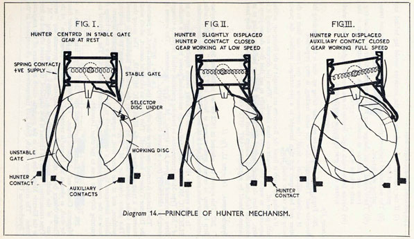
The Hunter (see Diagram 14) must also be lined up by its own lining-up knob
until the contact arms are dead central otherwise current will flow in the relays
as soon as the main switches are closed. Normally the hunter is lined up in the
"stable gate" with the director bearing directly ahead 000°. The " unstable
gate " is a mechanical feature of the hunter which permits lining up to be made
180° out of phase, such as may take place in the after director when it bears 180°,
i.e., directly astern. It is preferable that the after director be trained to 000°
during lining up procedure when its hunter should be centred with a broad arrow
on a disc in the hunter pointing to the letter "B" on the outer casing. It would
then be lined up in the "stable gate." If, however, the after director is bearing
180° during the lining up procedure, the hunter should be centred with the broad
arrow pointing to the letter "A." The hunter would then be lined up in the
"unstable gate."
Magslip.
290. This form of electrical transmission is the latest and best now in existence.
It came into service in 1938, and is found in all modern cruisers and larger ships.
There are two types of Magslip Transmissions, Indicator Magslip and Power
Magslip.
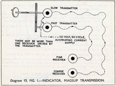
(i) Indicator Magslip. Diagram 15, Fig. I.
This system consists of a pair of Magslip Transmitters wired to a pair of similar
Receivers operated by alternating current. The Receivers follow to within one degree, any movement of their respective transmitters. One transmitter sends a
"coarse" movement, which covers the whole arc of movement of the directing
position, while the other is geared to send a fine movement, which is accurate
to within one minute of arc. This is necessary because an accuracy of one degree
is not good enough for Naval Gunnery.
102
ADVANTAGES:
(i) Magslip needs no lining up whatsoever.
(ii) It moves smoothly and not in steps.
(iii) It cannot get out of step, however fast the transmitters move, even if
power fails.
DISADVANTAGE:
The mechanism is delicate and Receivers cannot normally be repaired
on board.
Lining Up.
Not required. Just close the circuits.
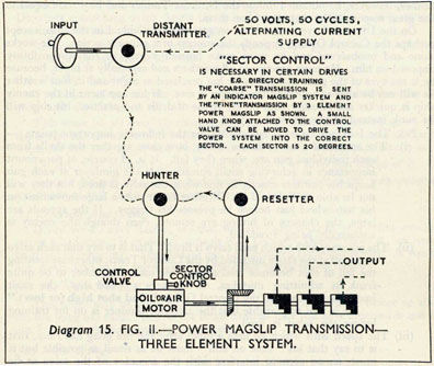
(ii) Power Magslip. Diagram 15, Fig. II.
291. Indicator Magslip has no appreciable mechanical power in its Receivers
beyond that required to drive the pointer. The pointers are made of very
delicately balanced aluminium strips. Power Magslip is the modern system, which
has the necessary power to drive into Fire Control Instruments.
It consists of a distant Magslip Transmitter, a Magslip Hunter and a local
transmitter or Re-setter, all connected by alternating current.
The Hunter, which is really a differential, follows exactly the movements of the
Distant and Local Transmitters and is connected to the Sensitive Control Valve
of an oil or air motor. When both the movements are equal, the movement from
the Hunter is NIL.
The sequence of events is that the Input Mechanical Drive (for instance the
movement of the Director Trainer's Handwheel), moves the Distant Transmitter.
The Hunter follows the movement exactly and so opens the control valve to admit
pressure to the motor one way or the other. The Local Transmitter or Re-setter
103
is moved by the Output Drive from the motor and the Hunter also follows the
movement. When the Output Drive has moved the same amount as the Input
Drive, the Hunter will be central, so closing the control valve and stopping the
motor.
On the sensitive valve of the oil or air motor will be seen a Sector Control Knob.
The reason for this is that, although Power Magslip has an accuracy of a quarter
of a degree, this is not accurate enough for gunnery purposes. The input drive is,
therefore, geared down, so that one revolution of the transmitter covers an arc
of only twenty degrees, giving an accuracy within one minute. The system is
thus self-aligning only in the particular sector of twenty degrees in which the
transmitter happens to be. An Indicator Magslip Transmission is therefore
incorporated in the same dial as the Power Magslip and an operator keeps the
power system in the correct sector, by keeping the Power Magslip pointer under
the Indicator Magslip pointer using the Sector Control Knob, which works the
sensitive valve of the motor.
ADVANTAGES:
The same advantages as in Indicator Magslip and has not the disadvantages
of Synchronous Transmission.
DISADVANTAGE:
The mechanism is delicate.
Lining Up.
No lining up is necessary, after initial installation. Sector Control is, however,
necessary and is particularly important
(i) When circuits are closed.
(ii) When the Director gets quickly on to a target.
(iii) After changing over Directors.
104
DIRECTOR LAYING AND TRAINING.
292. We have discussed so far in this chapter, the various instruments and
electrical transmissions that go to make the Director System of firing and in
para. 256 saw the reasons for adopting this form of firing. These full benefits
cannot, however, be obtained unless the Director Trainer and Layer are equal to
the great responsibility that rests upon them.
On the Director Layer, more than on any other individual in the ship, except
perhaps the Control Officer, depends the success of a gunnery action. He works
alone and unobserved and he must make himself worthy of the responsibility
imposed on him. He must practise in all weathers and especially at night, because
he is the eyes of the guns and unless he has practised at night and in foul weather
he will not be able to see when the enemy is met. If his opponent in the enemy
ship is quicker and steadier than he, by virtue of drills and practice, his ship will
be sunk instead of the enemy's.
293. The Director Layer is responsible for the following important points:-
(i) The spread of a salvo, that is to say, how close together the shells from
each individual gun are, when they fall. It is, of course, of paramount
importance in achieving small spreads, that the gunlayer at each gun
keeps his pointers exactly in line when the salvo is fired, but they will
not be able to do this if the Director Layer puts a large movement on
his handwheel just before he presses his trigger. If the spreads are
large, the chances of hitting are remote, even though the enemy is
continually being straddled.
(ii) The accuracy with which each salvo is fired. That is to say that each salvo
must fall at the range intended by the Control Team; otherwise spotting
the fall of shot becomes misleading. He must remember to be quite
frank in admitting mistakes. If he fires a "bad shot," he must
immediately report to the Control Officer "Bad shot high (or low)."
He is also responsible that the Director Trainer is on for training
before the salvo is fired.
(iii) The speed with which he fires a salvo after the fire gong has rung, that
is to say that his " time on aim " must be as small as possible but it
must, on no account interfere with the accuracy of the salvo or be
achieved at the expense of the gunlayers, who are following their
pointers.
Practical Working of a Director Sight.
(i) Reports to be made.
294. In order to open fire with the minimum delay, certain standard reports
must be made by the Director Layer, so that no confusion will arise.
When put on a LOOKOUT BEARING, report "Director on" as soon
as on.
When the enemy is reported in sight, get on as quickly as possible and report
"Director target" when the enemy is in the telescope field. It must be borne
in mind that other orders are being passed by the Control Team during this
period, so the report must be made in a loud clear voice, when few or no orders
are being passed to the Transmitting Station.
(ii) Standard Point of Aim.
The point where the vertical through the foremast cuts the horizontal on the
forecastle deck level.
(iii) Consideration for Gunlayers and Trainers.
The importance of this has already been stressed. Allow a slight pause before
firing, so that the electrical pointers at the guns are stopped and the gunlayers are
able to get their mechanical pointers in line. The length of the pause depends
105
upon the conditions and is especially important when the Director is controlling
POWER WORKED MOUNTINGS.
When the Director is controlling HAND WORKED GUNS, as long as the
motion is reasonable and in one direction, continuous laying and training may be
allowed but it is desirable to stop if possible. This does not apply to High Angle
Directors controlling High Angle Guns. The movement in this case must be
continuous in order to follow the target.
Reverse movements and sudden movements of the gun pointers just before
firing must be avoided at all costs.
(iv) Hunting the Roll.
The object of hunting the roll is to reduce the time on aim between the fire
gong and the firing of the salvo.
This must be achieved by moving the Director Elevation handwheel, so that
the horizontal crosswire of the telescope is in such a position relative to the target
when the fire gong rings, that the movement of the ship will quickly take it on.
Do not chase after the target. Run to meet it or keep just ahead of it.
Success depends on intimate knowledge of the behaviour of the ship under all
conditions of roll, and an enormous amount of practice.
(v) Reporting Bad Shots.
If you are a Layer Rating, see that you are quite clear in your mind when to
report a bad shot. If in doubt, consult your Gunnery Officer about it, but never
be afraid of reporting. The mistake can be accounted for if you report. If you do
not, it will lead to far worse errors in the other salvos which follow.
(vi) The order "Wait."
This order may be given to you by the Control Officer, either before or after
the fire gong has rung. Repeat the order to show that you have received it and do
not fire until the fire gong is rung again.
(vii) Night Firing.
You may not be able to see anything through your Director telescope if the
enemy is badly illuminated. Use your open sight or Aldis telescope. Plenty
of practice is needed to be able to see at night and make sure that the illumination
of the crosswire in your telescope is not so great that it blinds you. You will also
suffer from eye strain if the lenses are not clear and the focus is not correct. This
also applies by day.
Errors in Director Firing Due to the Roll and Pitch of the Ship.
(i) Due to Roll, Firing on the Beam.
295. When the ship is rolling and the guns are being fired on the beam, large
errors in the fall of shot will arise if the Director Layer presses the trigger
when he judges the crosswire to be exactly on the point of aim.
The errors are caused chiefly by the following:-
(a) The human lag; that is to say the time it takes for the eye to see, the brain
to appreciate and the finger to pull the trigger.
(b) The gun firing interval; that is to say the time taken after the trigger is
pressed for the circuit to be completed, the tube and cartridge fired
and the shell to travel up the bore.
(c) The "flip" either up or down given to the shell, as it passes up the gun
muzzle and leaves the muzzle due to the speed of the roll.
During (a) and (b), about two fifths of a second, the ship will be rolling and
106
the muzzle will have moved through an appreciable angle. This, combined with
(c), means that the guns must be fired before the crosswires reach the target;
low on an up roll and high on the down roll. The amount depends upon the speed
of the roll and the range, and can only be successfully gauged after a great deal of
practice. This is known as forecasting.
In Gyro firing, ships are fitted with an instrument which works out the error,
called TIME INTERVAL COMPENSATING GEAR. When this is fitted and
used, the normal point of aim is used by the Director Layer and the guns will fire
automatically at the correct moment high or low, as long as the trigger is pressed.
When using the unstabilised director telescope, the Layer himself must judge the
moment to fire.
(ii) Due to Roll, Firing on the Bow.
295A. When firing on the bow with the ship rolling, salvos will fall out of line,
owing to the fact that as the ship rolls across the line of fire, part of the elevation
angle becomes a training angle. For instance, in the extreme case of a ship
being rolled through 90 degrees, all the elevation angle would become training.
The error is called CANTED TRUNNION ERROR.
These line errors are extremely serious, especially during chasing actions,
firing ahead with the ship rolling heavily. They can be counteracted by firing
always at the same point on the roll but this cuts down the rate of fire, so an instrument called CROSS LEVELLING GEAR is introduced into the Director
Control Tower. This counteracts the errors, by moving the electrical pointers
in the Training Receivers at the guns.
107
CH. VII. SECTION 2. THE FIRE CONTROL PROBLEM AND
ITS SOLUTION.
296. Before continuing with the problem of engaging an enemy ship at sea,
it would be as well for the reader to go over Chapter I again, so as to be in no
doubt as to the general position of the Transmitting Station and of its main
functions. The general term given to the process of hitting the enemy ship
hard and often is FIRE CONTROL and the problem of how best to do this,
the FIRE CONTROL PROBLEM. As will be seen from Chapter I, the first
and obviously vital factor is to point out the enemy ship to be engaged to the
DIRECTOR, whose functions were dealt with in the previous part of this chapter.
"TARGET INDICATION
297. Target Indication, as its name implies, is the method by which the
Armament is directed on to the correct target, which is selected by the Captain.
If the enemy is visible this can be done by a Captain's Sight on the bridge
which transmits the bearing of the target to the director electrically. If the
enemy is not visible, but has been detected by Radar (see paragraph 351)
the movements of the enemy ship are plotted and the bearing and range of the
target chosen by the Captain is passed to the transmitting station. There the
information is set on the Admiralty Fire Control Table and goes to the Director
Control Tower and guns."
108
OBTAINING THE CORRECT RANGE.
298. The problem of obtaining the correct range, and thus the correct elevation for the guns, of an enemy ship that is moving and altering course from your
own ship, which is also moving and altering course, has three main points to be
considered:-
(i) Taking a range of the enemy ship.
(ii) Determining from the enemy's course and speed, and your own course
and speed, how this range is going to alter up to the moment of firing.
the guns.
(iii) Making allowances for the distance the enemy ship is going to move,
whilst the shell is in the air and also for any outside effects on the
shell as it travels through the air.
299. We will deal with these separately.
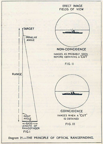
(i) The range of the enemy is taken by Radar or by optical rangefinders.
These are dealt with more fully in Section 3 of this chapter and here 't will suffice to
say that the range is taken in yards, as often as possible consistent with accuracy.
The larger number of ranges that are taken will obviously help to determine more
correctly the range at that particular moment.
(ii) The range, once taken, may not remain the same. If both ships are
moving away from each other, the range will increase more and more as time
goes on. This is known as " opening ". If both ships are coming towards each
other, the range will become less and less as time goes on and this is known as
"closing". The rate at which the range is opening or closing is known as the
RATE OF CHANGE OF RANGE or more shortly RANGE RATE. Thus, if
your own ship is stopped and the enemy is coming towards you at 15 knots, the
range would be altering at the rate of 15 nautical miles per hour or, converting it
into more convenient units, 500 yards per minute.
The course and speed of our own ship also affects the rate; and if we also move
towards the enemy at 15 knots, the closing rate will be doubled, namely 1,000 yards
per minute.
If both ships are steaming on parallel courses and at the same speed, there
will be no rate and the range will remain the same the whole time.
In order to keep the range adjusted for range rate, we use an instrument like a
clock, which is part of the calculating instrument in the Transmitting Station.
The adjusted range is known as the CLOCK RANGE.
Each time we get a new range from the rangefinders, we can check the Clock
Range. Radar should be able to give us a continuous measurement of range and
by doing this we can keep the Clock Range adjusted the whole time.
From this it can be seen that if we estimate the enemy's course and speed
correctly, we can get the correct rate of change of range. This we can check and
adjust continuously, so that the range is correct up to the moment of opening
fire.
(iii) As the shell takes some time to travel (called "Time of Flight") the
enemy will have moved closer or farther away from our own ship by the time the
shell has arrived. This distance has to be allowed for on top of our Clock Range.
Our own speed, especially if firing right ahead, will affect the speed of the shell as
also will the wind, the effect being greatest, so far as the range is concerned, if
firing straight into the wind or with the wind blowing directly behind the shell.
This will affect the distance the shell will travel, and so will the shape of the shell,
and the temperature and the density of the air, especially if they differ much from
the normal that is used in the design of the calculating instrument.
All the above are known collectively as the RANGE CORRECTION, and it
has to be added to or subtracted from the Clock Range, to get the most accurate
range to go to the gun, called the GUN RANGE. This Gun Range must now be
109
converted into an angle of elevation and goes to the electrical pointers in the
Elevation Receivers at the guns, which it will be remembered from the previous
discussion on Director Firing (see para. 276) are already being moved by the
Director Layer to counteract the roll of the ship.
Thus the final GUN ELEVATION is the correct elevation above the
horizontal plane for that gun range.
OBTAINING THE CORRECT LINE OF FIRE.
300. Having got the correct range, it is obviously equally important to get
the shells to fall on the correct line, if we are going to hit the enemy ship.
The target is indicated to the Director Control Tower, and the Director Trainer
training round until he is on the enemy ship, will send an electrical movement to
the TRAINING RECEIVERS at the guns, which follow up until they are on
the same bearing as the Director and, as the Director Trainer moves his training
handwheel to follow the enemy, so the guns will follow also. But on top of this
the guns must be given a certain amount of "Aim off" from the Director's
bearing.
This "Aim off" is called DEFLECTION and is calculated in the Transmitting
Station from whence it is sent to the Training Receivers at the guns electrically.
Composition of Deflection.
301. In the same way that the range has to be under or over-rated owing to
the fact that the range decreases or increases during the time of flight of the shell,
by the distance the enemy travels along the line of fire, so must the guns be
"Aimed off" to allow for the distance that the enemy travels across the line of
fire, during the time that the shell is in the air. This is the first part of deflection,
and the amount to be allowed for depends on the course, speed, and range of the
enemy.
For an enemy going straight across the line of fire at high speed and at long
range, the amount has to be large, if the shell and enemy ship are going to meet.
The amount decreases if the enemy alters course towards or away from you,
if he reduces speed or if the range, and hence the time of flight, gets less.
The second part of deflection is the sideways effect that your own speed has
on the shell, as it leaves the gun. If you are steaming at high speed and firing on
the beam, the shell will be carried bodily in the direction in which the ship is
going and if this is not allowed for the shells will fall out of line.
The wind blowing across the line of fire will also affect the shell, for this an
allowance must be made. DRIFT, already discussed in para. 269, will cause
the shells to fall off the correct line and this also must be taken into account.
SUMMARY OF THE FIRE CONTROL PROBLEM.
302. Summing up the above, to get the best gun range, we must:
(i) Take an initial range.
(ii) Calculate the rate of change of range.
(iii) Make range corrections for:
(a) The ENEMY'S TRAVEL along the line of fire during the time
of flight.
(b) The effect on the shell of our own SPEED along the line of
fire.
(c) The effect of WIND along the line of fire.
(d) The effect of the difference in the SHAPE of the shell, the TEMPERATURE and DENSITY of the air.
To get the shells to fall in line we must:
(i) Get the Director Control Tower and guns pointed at the enemy ship.
(ii) Keep the Director Control Tower on the enemy ship.
110
(iii) Aim the guns off for DEFLECTION, composed of allowances for:
(a) The ENEMY'S TRAVEL across the line of fire during the time
of flight.
(b) The effect on the shell of our own SPEED across the line of fire.
(c) The effect of WIND across the line of fire.
(d) The effect of DRIFT.
303. These calculations are made as accurately as possible in the Low Angle
calculating system in the Transmitting Station, and are discussed later in this
chapter. But, however accurate the instruments may be, certain errors are liable
to come in, owing to incorrect estimations of various parts of the problem, such as
the enemy's course or speed or the wind. These errors will make the shells fall
over, short, right or left and, as the shell splashes appear, so corrections are
made in order to bring the splashes on to the enemy ship. These corrections are
called SPOTTING CORRECTIONS.
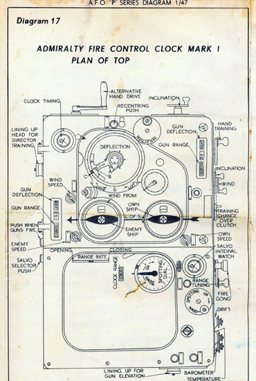
THE ADMIRALTY FIRE CONTROL CLOCK. Diagram 17.
304. The Admiralty Fire Control Clock is shaped like a box and is situated
in the Transmitting Station. Its function is to solve the Fire Control Problem,
previously discussed in this chapter, and to send away to the guns the correct
elevation and training for each salvo.
As will be seen from the diagram an arrow is engraved on the top of the clock,
which passes through two dials, one representing our own ship and the other the
enemy ship. This arrow is the LINE OF SIGHT, and the two dials give a representation of the relative positions of our own and the enemy ship. Also on the
"OWN SHIP" dial is a small red arrow, which shows the bearing of the Director
Control Tower and, unless there is a breakdown between the Director Control
Tower and the Transmitting Station, this small red arrow is on the same line as
the engraved arrow on the top of the clock, which shows that the Director Control
Tower is on the line of sight to the enemy.
305. Around the outside of the " OWN SHIP " dial is a gyro ring, worked from
the ship's gyro compass and the course of our own ship can be read off where the
bow meets the Gyro Ring. The " OWN SHIP " dial, once it has been lined up,
will be kept set automatically for any alterations of course by our own ship and by
the Director Control Tower training round on to the target. The speed of our
own ship is put on by a small knob and shows in a small window by the "OWN
SHIP" dial.
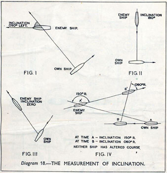
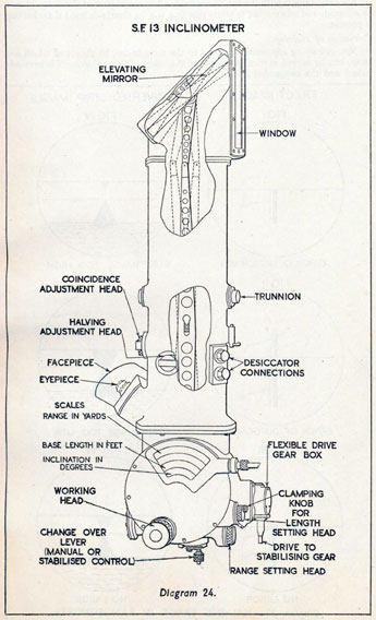
305A. The course and speed of the enemy are passed down by telephone from
the Director Control Tower and are set on the "ENEMY" dial. The enemy's
course is estimated in terms of INCLINATION (see Diagram 18). The inclination of a ship is the angle between the LINE OF SIGHT produced beyond
the enemy ship and her bows. The angle is measured in degrees right or left,
according to which way the enemy is going and is zero when the enemy
is going straight away from our own ship and 180 degrees when coming straight
towards. When going from right to left, the inclination is left, and from
left to right the inclination is right. Study Diagram 18, Figs. I, II and III
until this is thoroughly understood, because this method of estimating the enemy's
course is universal for all types of Fire Control Installations.
306. The inclination of the enemy ship can be set to whatever is ordered, by
means of the inclination handwheel and will be kept correct automatically by the
A.F.C.C., because the inclination of the enemy will alter when the compass
bearing alters, as long as both ships are steaming on a steady course. This can
readily be seen by Fig. IV in Diagram 18.
111
The speed of the enemy can be set by turning a small handwheel, wan it
shows in a window on the top of the clock, by the "ENEMY SHIP" dial.
Also showing on the enemy ship dial is a small yellow arrow, which is set to
the direction of the TRUE WIND by means of a handwheel, the force of the
wind also being set by turning another handwheel, until it shows in a dial on the
top of the clock.
307. All this information is passed down by telephone from the Director
Control Tower by the Rate Officer.
112
When the clock has been set the "picture" is complete.
The mechanism inside the clock now divides up the relative movements of our
own ship, the enemy and wind, sending away RANGE CORRECTIONS for
the travel of the enemy and the effect of wind along the line of sight. Deflection is calculated for the speed of our own ship, the travel of the enemy and the
effect of wind all across the line of sight, and also drift. It will be noticed
that the effect of our own speed along the line of sight is not allowed for in
this instrument.
The range of the ENEMY is sent down by a step by step transmitter from
the RANGEFINDER to a similar Receiver above the A.F.C.C. or to a RANGE
MATCHING RECEIVER alongside the clock from the Radar set. When this
range is received, one of the operators " tunes " the clock to the range, that is to
say, he moves the range tuning handwheel until the same range is showing on
the CLOCK RANGE counters, as is shown in the range receiver or matching
receiver. This gives us the initial range which is the first part of the problem.
The "Own" and "Enemy" dials, as has already been shown, are set and the
combination of the two, besides working out range corrections and deflection,
give the RATE OF CHANGE OF RANGE, which shows on a scale by the
Enemy dial and keeps the initial range up to date for RATE; this solves the
second part of the problem.
113
308. When the range corrections have been calculated they move the spotting
dial, marked in the diagram, which is to the left of the " Own Ship " dial. This
dial is also moved by the temperature and barometer settings, which are put in
at the side of the clock. Subsequent spotting corrections for range ordered by
the Control Officer are also applied to this dial.
When this spotting dial moves, the range operator follows the movement of
the dial with a pointer, by means of the SPOTTING HANDWHEEL and this
adds RANGE CORRECTION to CLOCK RANGE to give GUN RANGE.
This is converted inside the A.F.C.C. to ELEVATION by the RANGE TO
ELEVATION UNIT, and added to DIRECTOR ELEVATION from the
Director Layer's handwheel. The Dip from the Director to the standard level
is also added and the whole is sent away as GUN ELEVATION by step by step
electrical transmission to the electrical pointers at the Elevation Receivers at the
guns. This solves the elevation side of the problem.
309. Now to consider corrections for training. On the Deflection dial near
the top of Diagram 17 will be seen three pointers marked A, B, and C. When
the enemy and wind settings are applied a movement is imparted to pointer A.
During the lining up process pointer B was locked to pointer A and moves with it.
The amount of deflection due to own ship's speed across the line of fire offsets
pointer C. The operator, by turning the deflection handwheel, brings C into line
with A and B, and in doing so transmits total deflection. This is added to Director
training and drift and the whole goes away to the guns as Gun Training, appearing
as the angle shown by the electrical pointer in the training receiver. When
spotting corrections for line are ordered by the control officer the operator, moving
the deflection handwheel, moves pointer C by the amount ordered using the scale
on pointer B, having done this he re-aligns B with C by pressing the recentring
push, ready for any further correction to be applied.
310. On the A.F.C.C. will also be noticed a stop watch marked " salvo interval
watch " and a fire gong push. The watch is set for the interval between broadsides
and the fire gong is pressed at the end of that time. This rings a gong at the
Director and at the guns and is the permission for the Director Layer to fire.
There are also gun range and deflection counters, which show the gun range and
deflection that is being sent away to the guns, as well as gun elevation and
training (range and deflection are used for setting the sights at the guns when
they are being laid and trained by telescope in Gunlayers or Quarters Firing
(see para. 343) ). The dials to the left and below the spotting dial were used when
"concentrating" with other ships, but are now obsolete.
311. A " Time of Flight " push is also included on the left of the clock. This
is pressed in when the guns fire and, by means of a mechanism inside the clock,
work a rattler in the Director Control Tower when a broadside is about to fall.
This helps the Control Officer to identify the fall of the broadside.
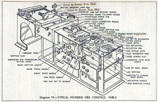
TYPICAL MODERN FIRE CONTROL TABLE. Diagram 19.
312. This is a larger instrument than the Admiralty Fire Control Clock, and
is found in the TRANSMITTING STATIONS of modern cruisers of the types
shown in Plates1 and 2.
Its function is to solve the Fire Control problem. It is a more accurate instrument than the A.F.C.C., although it is based upon the same principles and
likewise sends to the guns, gun elevation, gun training, range and deflection.
114
115
The central portion of the instrument is very similar to the A.F.C.C., the main
differences being as follows:-
(i) There is a TRUE RANGE counter beside the " Own " ship dial, as
well as a CLOCK RANGE and GUN RANGE counter.
(ii) There are two dials showing the DIRECTOR ELEVATION being sent
down from the Director in the Director Control Tower by Magslip
transmission.
(iii) There are two scrolls which are used in bombardment for correcting the
gun elevation for the height of the target.
(iv) There is a DIRECTOR/T.S. change-over switch and a TARGET
VISIBLE LAMP.
(v) There are two wires over the ENEMY DIAL, whose functions will be
explained later, a " Dummy ship " engraved on glass over the dial
and also a pointer on the Enemy dial, showing the inclination that is
being measured by the INCLINOMETER in the Director Control
Tower.
313. The modern F.C. table differs, however, considerably from the A.F.C.C.
in that it is equipped with PLOTS at either end of the centre clock portion, and
also by the method of transmission from the Director to the Table, and the Table
to the guns being Magslip, as opposed to synchronous and step by step, although
step by step transmission is still used in certain cases.
The functions of the various parts of the A.F.C.C. having already been explained in some detail in paras. 304 to 311, these paras. can be taken to apply in a
general way to the central portion of the F.C.T. to which it is very similar. We
now go on to explain the functions of the plots.
314. The plot immediately to the left of the centre portion of the table is the
Range Plot. This is used to get the most accurate range from the Rangefinders
before opening fire. The Rangetakers in the Director Control Tower take ranges
and these are sent down electrically to pointers on the rangefinder range dial,
by the side of the range plot. An operator follows these pointers with another
pointer by moving the " Rangefinder Range Follower Handwheel " and when the
appropriate "CUT" lamp burns, presses a push beside the dial. By turning this
handwheel a typewriter above paper plot is moved and when the appropriate
push is pressed, the typewriter marks the paper at the correct rangefinder range.
There is a push for each rangefinder in the ship and consequently, when ranges
are being taken, a series of typewritten marks will appear on the plot as it moves.
The range tuning operator then positions the pen on the plot, until it is in the
middle of these marks, by means of the range tuning handwheel, on the front of
the instrument, and by so doing tunes the table to the best TRUE RANGE. This
plot can also be used as a diary of events for analysis purposes, because the pen on
the plot is moved when any range spotting is applied.
315. To the left of the rangefinder plot is the spotting plot. In various
places around the ship, spotters are situated, whose sole duty is to look intently
at the enemy and to note when each salvo falls, whether it is over, short or
straddling. The spotters then each press a push in the "Spotter
Observation Push Box" at their positions, which burns a light in the "Spotter
Observer Lamp Box," which faces the spotting plot operator.
E
116 and 117
118
The spotting plot operator thus sees from the lights that are burning, whether
the spotters consider the salvo to be over, short or straddling. He
marks this information on the plot as it moves and is thus able to note the direction
of the target relative to the fall of the broadside and to order the appropriate
spotting corrections. The spotting corrections are applied, as in the A.F.C.C.
on the spotting dial by the range tuning operator, using the spotting handwheel.
316. Over the Table are one or more RANGE MATCHING RECEIVERS,
which can be used to follow the Radar, ranges being sent from the Radar ranging
panels in the Transmitting Station or Radar Office.
On the same paper as the spotting plot is an " Error in Range " plot on which
is plotted the difference between the range that is being calculated in the table
(in the same way as in the A.F.C.C.), and the range being measured continually
by Radar. From the slope of this plot can be found whether the inclination
and speed of the enemy set on the table agrees with that being measured, and
when a " suggestion " is obtained from this plot, one of the wires over the enemy
dial is moved. The other wire is moved by suggestions from the plot at the
opposite end of the table called the SPEED ACROSS PLOT. This plot compares the relative speed across the line of sight that is being measured by the
Director Control Tower as it follows the target with the relative speed
across calculated by the table. The clock operator, by positioning the
dummy ship mentioned in para. 312 on the enemy dial over the intersection of the two wires, can tell the rate officer that the plots suggest a different
enemy inclination and speed to that already in the table or it may suggest that the
enemy has altered course. If the rate officer in the Director Control Tower
accepts these suggestions, the new enemy settings are put on the table.
317. The speed across plot also enables the Director Control Tower to be kept
on an invisible target, which might be behind a smoke screen, as its bearing changes.
This is called BLIND FIRE and is not dealt with in this book, except to say that
it can be carried out, as long as means are available to spot the fall of shot; there
are arrangements on the Speed Across Plot to make line spotting corrections based
on the reports received.
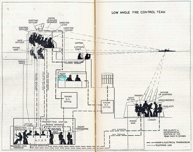
THE FIRE CONTROL TEAM. Diagram 20.
318. Once the enemy ship to be engaged has been pointed out by the Captain,
it is the job of the Fire Control Team to hit that enemy ship quickly, to hit her hard
and to go on hitting her.
The considerations that have to be taken into account in the Fire Control
problem and the instruments that are fitted in ships to solve that problem have
already been discussed. This part of the chapter is confined to the part that each
member or group of the Fire Control Team undertakes, so that by working
together as a team, they produce the best answer out of the Fire Control Installation of the ship. The size of the team varies, naturally, with the size of the ship
and here the ship is taken as a "Dido" class cruiser (see Plate2).
Composition of the Team.
(i) The Control Officer.
319. He is the leader of the team and may be the Gunnery Officer. He
supervises the whole of the team from the centre position in the rear of the
Director Control Tower, where he is near to the other members of the crew of
the D.C.T. and can talk by telephone to the Captain, the officer in charge of the
Transmitting Station, the spotting group and the rate group. He has powerful
stereoscopic binoculars, mounted immediately in front of him, with which he can
see the enemy ship.
119
(ii) The Primary Spotting Officer.
320. He is the head of the spotting group, consisting of himself in the rear of
the D.C.T., to the right of the Control Officer, a " spotter " in B Turret and a
"spotter" in the After Director. In the Transmitting Station the spotting group
consists of the officer in charge of the T.S., the spotting plot operator and the
deflection spotting operator. In front of him and each spotter is a box with three
pushes marked "OVER," "STRADDLE" and "SHORT." He looks intently
at the enemy through stereoscopic binoculars in front of him and when a broadside
falls, presses the appropriate push in the spotter observer push box. The primary
spotting officer is also responsible for giving the necessary orders to get the guns
in action as quickly as possible and for keeping the broadsides in line with the
enemy.
(iii) The Rate Officer.
321. He is the head of the rate group, consisting of himself in the rear of the
D.C.T. to the left of the Control Officer, the Rate Officer in the After Director,
and the Clock Operator in the T.S. The Rate Officer's job is to estimate the
enemy's inclination and speed, by looking intently at the enemy ship through
stereoscopic binoculars mounted in front of him, and also to note as soon as the
enemy alters course or speed and to pass this information to the T.S. He is assisted
by "suggestions" from the T.S., given by the "Speed Across Plot," the Radar
"Error in Rate Plot" and by the INCLINOMETER, which is mounted just in
front of him. He must be thoroughly acquainted with the capabilities of each of
these instruments, because upon him rests the responsibility of accepting or
refusing the suggestions given to him.
(iv) The Director Crew.
322. The Director's Crew comprises the Director Layer, the Director Trainer
and The Cross Level Operator (seeDiagram 9). Their importance in the team is
very great. The duties of the Director Layer and Director Trainer are outlined
in para. 292 et seq.
(v) The Radar Operators.
323. These are very important members of the team. The Radar operators
man the Ranging panels of the Low Angle sets in the Transmitting Station or Radar
Office. Their duties are to take accurate ranges continually throughout the action,
thus giving both an accurate range for opening fire and accurate measurement of
rate. They may also be able to spot the fall of shot on the trace.
"Radar operators also man the bearing panels and their duty is to keep
the director pointing at the target in blind fire".
(vi) The T.S. Crew.
324. They are under the supervision of the officer in charge of the T.S. and
are all responsible for the accurate elevation and training being sent to the buns.
The range spotting operator, especially, must realise that range spotting alters the
elevation being sent away, as well as the movement of the Director Layer's handwheel and must not press the fire gong until he has completed the spotting corrections being applied. All the members of the crew of the table must realise that
the best results will only be obtained from the table by careful drill and concentration.
(vii) The Aircraft Observer.
325. If an aircraft is available for spotting, the aircraft observer is an extremely
important member of the team, even though he is away from the ship. He is of
great assistance to the rate group, especially in passing alterations of course quickly
and is the only member of the spotting group, who can judge the distance over or
short of each broadside, except perhaps the Radar operators.
120
(viii) The W/T Ratings.
326. When an aircraft is available or when bombarding, the W/T operators
in the T.S. crew are extremely important. Speed in receiving and transmitting
signals, combined with good drill and understanding of the problem, are the
attributes required in these members of the team.
(ix) The Rangetakers.
327. These are as important to the success of the action as the Radar operators,
and are entirely relied upon should the Radar sets fail. Daily drills, constant practice in all sorts of weather and careful adjustment of the optical rangefinders are
required.
(x) The Guns' Crews.
328. The importance of pointer following has already been stressed. The
guns' crews are responsible more than any other members of the team for the
spread of the broadside. Unless the spread is small, the enemy will never be hit
hard and correct spotting on the fall of shot will be very difficult.
ORGANISATION FOR NIGHT ACTION.
329. At night, even more than by day, precise drill and strict discipline are
essential if fire is to be opened quickly and accurately. In the dark, unless every
man knows his job thoroughly, thinks quickly and reports clearly, confusion is
bound to arise. Speed is essential, because night actions may be fought at short
ranges and the ship which opens fire first has an enormous advantage.
The organisation of the ship for night action is kept as nearly as possible to that
for day action but differences have to be made, especially in the long range High
Angle armament, which is used for firing Star Shell (see para. 30). On the bridge,
the Captain is fully occupied handling the ship to bring the maximum amount of
gun power to bear upon the enemy. The conduct of the action, once fire has been
opened, is the duty of the PRINCIPAL CONTROL OFFICER, who is also
stationed on the bridge close to the Captain. The Principal Control Officer is
responsible for illuminating the target sufficiently for the Director Layer to
see the point of aim on the enemy ship. He has under him the STAR
SHELL CONTROL OFFICER at the Star Shell sights on the bridge. These
latter are the A.D.O.'s sights by day.
330. In cruisers and larger ships, the Star Shell sight is connected to a STAR
SHELL DEFLECTION CALCULATOR, which sends the correct gun
training to the star shell guns, on an open faced indicator at the guns. The
star shell guns fire TIME-FUZED STAR SHELL, which contain a star on a
small parachute (see para. 199 (ii)). The fuze is set to burst 1,500 yards beyond
the enemy ship at a height of about 2,000 feet. The guns are elevated to achieve
this and are laid by means of a spirit level on the mounting, so that when the
spirit level is central, the guns are at the correct elevation from the horizontal.
The guns are controlled from the bridge by the Star-Shell Control Officer and
are fired by the gunlayer at the gun, when the fire buzzer which is worked
from the bridge is sounded.
In destroyers, where there is no star shell deflection calculator, the necessary
deflection is estimated by the Star Shell Control Officer and passed by telephone
or voice pipe to the star shell gun. (See para. 38.)
331. The following points should be noted:-
(i) The enemy's probable inclination and speed are set on closing up in
the T.S. and at the Star Shell deflection calculator. When sighted
121
they are estimated as quickly as possible but it may only be possible
to pass the direction in which the enemy is going, in this case an
inclination of 135 degrees right or left is set and the maximum probable
speed of the enemy.
(ii) The fines are set in accordance with the range of the enemy. The old
practice of having three fuze settings only (long, medium and short)
is no longer used.
(iii) The report "On" is given by any directing position when on the
bearing ordered, and "Target" when the Control Officer can see the
target in his sight.
(iv) The challenge is made in code, by using combinations of coloured lights
or by sending a special signal which is changed every few hours.
(v) The armament is always ready to open fire before the challenge is made,
so that if no reply or the wrong reply is received, fire can be opened
immediately.
STANDARD METHODS OF PASSING ORDERS.
332. To prevent people finding new methods in force in each ship to which
they go and to avoid confusion, all orders have to be passed in a certain standard
way, as follows:-
"Range
Each figure in the range is to be called separately, omitting the last two
figures. The figure 0 is to be called 'ZERO'. Three figures are always to be
used when passing a range if necessary, 'ZERO'S' are placed in front of the
figure. The word 'yards' is inferred and never spoken.
Examples:-
'Two-one-five' means 21,500 or 21,550 or 21,525;
'One-zero-zero' means 10,000;
'Zero-nine-two' means 9,200;
'Zero-zero-eight' means 800."
Range Spotting Orders.
333. To distinguish these clearly from ranges, the word " up " or " down "
is to precede the amount, the word " yards " is omitted and the amount is to be
passed in words instead of figures.
Example:-
"Up two hundred."
Bearing.
334. When RELATIVE BEARINGS are being passed, the word "red" or
"green" is always to precede the amount and each figure is to be called
separately.
" red "
Example:-
"Red one five zero" means that the relative bearing is 150 degrees from
right ahead on the port side.
When GYRO BEARINGS are being passed, the word " bearing " is always
to precede the amount and the amount always called as three separate figures,
if necessary noughts being placed in front to make the three figures.
Deflection.
335. For TOTAL DEFLECTIONS each figure is called separately, followed
by the words "right" or "left,"
122
Examples:-
"One-two right" means a total deflection of 12 to the right.
"Seven left" means a total deflection of 7 to the left.
For DEFLECTION SPOTTING CORRECTIONS the words "right" or
"left" are to be followed by the amount in words.
Example:-
" Right twelve " means apply twelve units more right deflection to that
already on the transmitter.
Inclination.
336. The numeral value of the inclination is called by three separate figures,
followed by the words "right" or " left." The words "right" or "left" indicate
the direction in which the enemy is steaming but the words " to the " are omitted.
Example:-
"Inclination zero-one-zero-right" means that the inclination of the enemy
is ten degrees to the right of the line of sight.
If the enemy is steaming directly away from the observer along the line of sight,
it is said to be zero. If the enemy is steaming directly towards, the inclination is 180.
"337. Speed is passed in knots, preceded by the word 'Speed', as in
examples. The word 'knots' is omitted."
Examples:-
338. The word "rate" is passed, followed by the amount in words and then
followed by the words "opening" or "closing."
Example:-
"Rate two hundred closing" indicates that the range is shortening by
200 yards every minute.
Wind.
339. The word " wind " is passed, followed by the speed or force and then the
direction from which it is blowing.
Example:-
"Wind 40 f.s. from green 120" means that the speed of the wind is 40 feet
per second and that it is blowing from green 120 degrees, or "Wind Force 4
from red 90" means that a wind of force four is blowing from red 90.
METHOD OF USING TELEPHONES.
340. Using a telephone requires practice in the same way as any instrument.
The first essential is to know what you are going to say, to say it clearly and
distinctly and to keep your mouth close to the mouthpiece. When calling up on a
telephone, first name the position from which you are calling, following it up with
the place that you want. For instance, when calling up from the bridge to the
Transmitting Station, start by saying "Fore bridge-T.S." When the T.S.
answers by saying "T.S.-Fore bridge," send your message.
Always repeat any message given to you on a telephone, because otherwise
there is no means by which the sender can tell whether the message has been
received correctly.
If you do not hear the message, pass Say again When
testing your telephone on first closing up, call up in the usual way, and when
answered give the report "Well," i.e.,
POSITIONS FOR CONTROLLING AND METHODS OF FIRING
THE GUNS.
341. In action, if the ship is damaged, it may not be possible to control and
fire the guns from the D.C.T. Alternative means are therefore provided for both
controlling and firing, but the guns should always be fired together and controlled
from some central position, if possible, to avoid any confusion in spotting the fall
of shot and to maintain the heaviest hitting power.
Alternative Positions for Control.
342.
Primary Control. Control by the forward and/or after director (or control)
position through the transmitting station.
Secondary Control. Control from any convenient position or mounting
through the transmitting station.
Emergency Control. Control from any convenient position direct to turrets
or mountings.
Group Control. Control by officer of quarters of two or more turrets or
mountings.
Local Control. Control by the officer of quarters of a single turret or
mounting.
Gunlayer's Control. Control of guns by their gunlayers in the absence of
the officer of quarters.
Divided Control. Simultaneous engagement of two enemy ships by the
forward and after parts of the armament respectively, controlled by
corresponding control positions.
Methods of Firing.
343.
Director Firing. All guns are fired by a single layer at the director sight.
Gyro Firing. The Firing Circuits are closed by the Gyro Firing Gear.
Local Firing. The gun is laid and trained by following Director or table
and fired by the local arrangement at the gun.
Gunlayer's Firing. The gun is laid and fired by the Gunlayer or Local
Sight Layer, but the training is by director.
Quarters Firing. The gun is laid, trained and fired by means of its local
sighting and firing arrangements.
Note. Care should be taken not to confuse the position from
which the guns are controlled, with the method by which they
are fired. For example Primary or Secondary Control can still be
used although the guns may be in Quarters Firing. Any controlling
position is better than at the gun itself and should be used where
possible.
GUNLAYER'S CONTROL.
344. The following procedure is applicable in all classes of ships to a single
gun controlled by its gunlayer.
Opening Fire.
Fire one round with the estimated range and deflection on sights. If the
round falls out for line apply a deflection correction of at least 4 units (8 knots)
towards the target. This correction is to be repeated until line is established,
or the target crossed for line.
When the target is crossed for line, apply a suitable correction in the reverse
direction.
124
Notes:
(i) If the round is not seen, apply down corrections of 800 yards without
change in deflection, and fire single rounds until a splash is seen;
then proceed as above. If the first estimate of range is thought to be
seriously in error, re-estimate and order a new range to be set.
(ii) Except in the case given in (i), never correct for range until shots are
in line with the target.
Maintaining Line.
345. Normally, the tendency for shots to creep right or left should be
countered by deflection spotting corrections of not less than 2 units (or 4 knots),
but with small end-on targets, steps of 1 unit (or 2 knots) may be necessary.
Should more than two successive shots fall far out for line, however, the
target is to be considered lost for line and is to be regained as laid down in
para. 344 above.
Finding the Range.
346. If, after line is established, shots are observed over or short, correct
towards the target in steps of 800 yards, and fire single rounds until the target
is crossed.
Every time the target is crossed for range, apply half the last correction in
the reverse direction before firing again.
If this reverse correction fails to cross, corrections of the same value are to be
repeated until the target is crossed.
When the size of the bracket has been reduced to 100 yards, assume hitting,
and fire as rapidly as possible.
Target Lost.
347. If the hitting range is correct, the normal error of the gun and gunlayer
will make occasional shots fall over or short. If therefore, three successive rounds
fall on the same side of the target, it is to be considered as lost, and the procedure
to be adopted is that given in para. 348 below.
Regaining the Range.
348. If the target is lost for range the gunlayer is to check fire in independent,
and is to regain the target by the use of a 400 yards bracket, as laid down in para.
346 above.
. . . care should be taken . . . (para 246)
CH. VII. SECTION 3. THE PRINCIPLES OF RADAR,
OPTICAL RANGEFINDERS AND INCLINOMETERS.
RADAR.
Nature of Radar.
349. Radar is the term used by the Services to describe Radiolocation, a
method of using radio waves to determine the position of a target.
Radio waves are known to travel in space at a speed of about 163,000 sea miles
125
per second. It is also known that when they impinge upon an object, they are
reflected by it in all directions.
Radar sets have a transmitter, which sends out pulses of radio waves and a
receiver, which receives these pulses, both from the transmitter and from any
object which reflects them.
Transmitter and receiver are each coupled to aerials, which concentrate
the waves into a directional beam.
350. To the receiver is connected a device, which displays radio impulses
in the form of areas of light upon a screen and from which microscopically small
intervals of time can be read off, by measuring the distance which separates these
areas. The screen upon which this display is given is part of a cathode ray tube.
From the appearance also of these areas, which are caused by reflected impulses
(called "echoes"), the bearing of the reflecting target can be determined.
Display units are variously designed for measurement of ranges (ranging
tubes), bearings (training tubes) and angles of sight (elevation tubes). Furthermore, since when a transmitter is running, an echo from a target will be almost
continuously visible on a ranging tube, it is possible to use such a tube for
measurement of rate.
Uses of Radar.
351. Radar sets differ in design according to the function required of them.
There are sets used for warning of the presence of aircraft and for fighter direction,
for warning of the presence of ships, for target indication, for the control of long
range gunfire against aircraft and against surface targets, and for control of close
range weapons. Sets can also be used for navigation and for torpedo control and
they will provide the data necessary to measure a target's course and speed (and
hence its inclination) as well as to enable one vessel to shadow others unseen.
Limitations of Radar.
352. Radio waves will travel through space by day and night, in calm and
storm and in clear or thick weather. Radar can thus be used at all times at sea.
It can be used on land and in the air. Since, however, a target only appears on the
screen of a cathode ray tube as an echo, no indication of the nature of the target
is given, such as the human eye receives, when it sees the target through glasses.
Nor, owing to the nature of radio waves and the aerials used to propagate them
directionally, can Radar ever be quite as accurate for bearing as the human eye.
For range, however, if the display instruments are properly adjusted, Radar
achieves a far greater accuracy than any optical instrument.
Involving, as it does, radio transmissions, the use of Radar may give away to
an enemy equipped with the necessary gear, the position of own ship. Likewise,
since radio transmission may be interfered with or "jammed" by other radio
transmissions, it is possible for an enemy to jam and prevent the use of a certain
number of Radar sets.
Generally, however, the uses of Radar are so great as entirely to outweigh its
limitations.
Radar Operators.
353. Radar is now as integral a part of gunnery as the director. Radar
operators must be as scrupulous in lining up and checking their instruments as are
the gunlayers, at every dawn and dusk Action Stations and at Quarters Clean
Guns. They must also check over their telephones.
Success with Radar, as with any other part of the gunnery equipment, is
achieved only by constant practice. Radar operators should practice at least once a
day, taking ranges and bearings of objects.
If this is done every day, you will find that the set will be working correctly
when you meet the enemy. If you spend a week in harbour and do not use the set
126
at all, you will probably find, on going to sea, that there is some small defect which
should have been discovered three or four days previously.
Of course, there are occasions at sea when you are unable to transmit and
use your set, owing to wireless silence being enforced.
OPTICAL RANGEFINDERS.
354. Full information on the theory and details of rangefinders can be found
in the Handbook of Naval Rangefinders and Inclinometers which is kept in the
gunnery office It may, however, fall to the lot of any seaman to be the trainer at
a rangefinder or even to have to take ranges himself, so this section of the chapter
is intended to give a very elementary knowledge on how to use the instrument.
The Use of Rangefinders.
355. Rangefinders are used for finding the range of the target before opening
fire and also to assist in keeping the range correct during firing. There are varying
numbers of rangefinders in different types of ships. As a range is obtained it is
sent to the transmitting station and a cut lamp push is pressed by the operator of
the transmitter. This lamp burns in the T.S. and indicates that the reading on the
rangefinder range receiver at the moment is the range to be used.
Principle of Coincidence Rangefinder. Diagram 21, Fig. I.
356. The coincidence rangefinder obtains the range of an object by measuring
the angle subtended by the rangefinder at the object. The size of the angle depends
on the length of the rangefinder and the range of the object. As the former remains
constant, any angle will have a definite corresponding range; therefore, although
an angle is measured, the scale on which the answer is shown can be marked
with the range.
The length of the rangefinder is small compared with the range of an object,
and the angles involved are, therefore, very small. At long ranges the angles
are extremely small, and at short ranges the angles are relatively large. Ranges
and angles do not change at the same rate. For instance, a change in angle of,
say, one minute will have a much smaller effect on range at short ranges, than at
long ranges. This has the following results:-
(i) The spaces between graduations for a given number of yards on the
range scale decrease as the range increases.
(ii) An error in measuring the angle has a greater effect at longer ranges.
(iii) A long rangefinder is more accurate than a short one, because a long base
length increases the size of the angles to be measured.
Focus.
357. Focus is the power of the human eye to adjust itself to see things clearly
at different distances. The eye does this automatically, but when an optical
instrument is used, the instrument must be focused to suit the individual's eyes.
The human eye is normally focused for distant vision and can be used in this
state without strain for longer periods than in any other position.
The rangefinder should therefore be focused so that the object is seen clearly,
with the eye accommodated to distant vision.
Although the right eye only is used, both eyes should be kept open when
focusing and when ranging, as this helps to relieve eyestrain.
On all instruments, the focus adjustment is fitted with a scale. When a satisfactory focus has been obtained, the reading on the scale should be noted, and on
future occasions the correct focus can be set by the scale.
Magnification or Power.
358. Rangefinders are fitted for one, two or three powers varying from 15 to 28.
127
Where a choice is provided, the highest power should be used when conditions
of light are very good. Low power should be used at night and in poor visibility.
Changing the power does not affect focus.
Taking a Range.
359. A face piece is fitted near the centre of the rangefinder, and with one or
two exceptions, contains two eyepieces. The left hand eyepiece gives a view of
the range scale, the right, a view of the object. Both eyepieces can be focused,
but the right only can be adjusted for power.
128
The rangefinder is so designed, that the picture which the rangetaker sees
when he looks through the right eyepiece, is a combination of two pictures, one
from each end window of the instrument.
Although the form of the picture varies with different types of rangefinders,
the rangetaker's problem is the same in all cases; he has to make two parts of
the picture fit exactly. When he has done this, he is said to have taken a "cut,"
and the range of the object can then be read off the range scale.
The rangetaker can move one part of the picture horizontally, relative to the
other part by means of the working head.
The drill for taking cuts will be explained later.
Types of Field.
360. The picture that the rangetaker sees when looking through the rangefinder is called the " field."
Upright Field, single separating line. (Diagram 21, Figs. II and III.)
In most L.A. rangefinders a fine horizontal line runs across the centre of the
field. This is called the "separating line." The picture above the line comes from
one end window and that below comes from the other. If the rangefinder is
moved in elevation until the separating line cuts an object, it will be found that
the part of the picture above the line is either to the right or to the left of the
part below the line. By turning the working head, the two parts can be brought
into line. When the two parts fit exactly, the angle has been measured and the
range of the object can be read on the scale.
To obtain a perfect cut, it is necessary to select some particular part of the
object, and with this type of field, a vertical clear-cut line, such as a mast, or edge
of a funnel, is best.
Inverted Strip Field. (Diagram 22, Figs. I and II.)
When ranging on aircraft, which do not present vertical straight lines on which
to cut, the single separating line and upright picture is not satisfactory. Range-
129
finders for H.A. work, therefore, have different types of field, the commonest of
which is the inverted strip field.
In this type there are two horizontal lines and the picture seen between the
two lines is an upside down duplicate of that seen immediately below the lower line.
The picture in the strip comes from one end window, all the remainder of the
field comes from the other. The bottom separating line must be used when
ranging.
If the rangefinder is moved in elevation it will be seen that the pictures in, and
below, the strip will move towards or away from each other. The rangefinder is
laid so that both pictures are touching the bottom line and a cut is obtained by fitting
a part in the strip to the duplicate below the line.
Astigmatizers.
361. It is sometimes necessary to range on a light, i.e., a gun flash, signalling
lamp or a star. Astigmatizers affect the appearance of the object in much the
same way as a curved mirror does, drawing the object out into a vertical streak,
thus presenting the rangetaker with the most suitable shape on which to "cut."
They can be swung into the beams of light inside the rangefinder by means of a
lever.
Astigmatizers are seldom of use for ordinary objects, because of lack of contrast between the object and its surroundings, and if used, will produce a streaky
field in which the object cannot be recognised.
Light Filters.
362. These are provided for all rangefinders as follows:-
Yellow.
Used in haze or mist, when the air contains
moisture.
Light or dark neutral.
Used when ranging close to, or in to bright sunlight
or reflection of sun's rays on the water, or on
searchlights.
L.A. Ranging.
363. After the lining-up procedure has been carried out, the illumination to
the range scale is switched off to prevent the rangetaker being influenced by
previous readings. As soon as the target is seen, the rangetaker takes a cut, and
when satisfied, makes the cut switch. The breaking of the cut switch indicates
that the range has been plotted, and the rangetaker is then free to take another
range, but before doing so he throws the cut off by moving the working head.
This ensures that each range is an independent effort. The cut should be thrown
off high and low alternatively, but sometimes the rangetaker may be ordered by the
T.S. to throw off in one direction so as to cut against the rate, i.e., if the rate is
closing, the rangetaker would be ordered to throw off low. The actual order
given would refer to the working head wheel in terms of "clockwise," or "anti-clockwise."
Use made of Ranges.
364. Two distinct uses are made of rangefinder ranges:-
(i) They are the basis of gun range for opening fire.
(ii) The rate of change of range obtained from the range plot is compared
with the rate in use, to assist in obtaining the correct enemy speed and
inclination.
130
As the accuracy of the initial salvos is dependent on the mean R/F range,
the necessity for quick and accurate ranging is obvious. Having opened fire,
if all rangetakers transmit accurate ranges and plenty of them, a compact and
steady range plot will be produced, from which good suggestions can be obtained.
If the ranges sent down are inconsistent and infrequent, the plot will be irregular
with a large spread. From this type of plot any suggestions obtained will most
probably be misleading.
The secret of good ranging is to practice, not only in fine weather, but especially when the visibility is bad and the ship is rolling. It is under these conditions
that you will probably meet the enemy.
365. A rangetaker must help the officer in charge of the rangefinders to keep his
rangefinder analysis chart, which will probably be kept in the gunnery office.
The idea of this analysis chart is that the adjustment of a rangefinder is not
"fiddled with" but the fact that you do a comparison run with another rangefinder
or with a Radar set ensures that the officer in charge of the rangefinders knows
exactly how your instrument is behaving.
366. The adjustment of a rangefinder must never be altered without the
approval and supervision of the rangefinder officer.
It is best to get the instrument into adjustment at the beginning of a commission
and then to leave it, accepting a small error, as long as the rangefinder officer knows
what this error is. If, however, a rangefinder is being continually altered and
adjusted, it will be difficult for the officer in charge of rangefinders to know how
it is behaving.
Halving Error.
367. When taking a cut, one part of the image is moved laterally, relative
to the other part, and made to fit.
To do this accurately, it is necessary that the parts of the pictures coming from
both ends of the rangefinder shall appear at the correct height relative to each other.
Considering the double image field, if one image is higher than the other, although
correctly in line with each other laterally, they will not show up clearly, and unless
there is a vertical line, it will not be possible to see when an accurate cut is
obtained.
The difference in height of the two parts of a picture is called halving error.
368-"Detection of Halving or Height of Image Error (Diagrams 23 and 23A).
A test for halving error should be made, if possible, immediately on
closing up on all occasions, and the instrument should be checked if there is
any considerable change of temperature during the watch.
The instrument is most easily tested as follows:-
(1) Direct the instrument on to the nearest well-defined object.
(2) Obtain an approximate cut.
(3) (a) With 'erect image' fields.-Move the rangefinder in elevation
until the object is in the lower field, then slowly depress the
rangefinder until the separating line crosses the top of the object.
If the top of the target appears in the upper field before it
has reached the separating line in the lower field there is an error
of duplication (see Diagram 23).
If the top disappears from the lower field and does not appear
in the upper field there is an error of deficiency (see Diagram 23).
When the separating line crosses the target without distortion
of any kind, then the rangefinder is correctly adjusted for halving
(see Diagram 23).
131
5 A.F.O. P.75/47
(b) With the strip image or inverted image field of view.-The method of
detection is slightly different and the error is called 'height of
image error'. The error is detected by moving the rangefinder in
elevation until the object is in the lower field and then slowly
depressing the rangefinder until one of the images touches the
separating line.
If the other image touches the line at the same time, no error
exists (see Diagram 23A).
If the lower image touches the line first, the image is too high
(see Diagram 23A).
If the upper (strip), image touches the line first, the image is
too low (see Diagram 23A)."
(G. 6619/46.-A.F.O. P.75/47.)
132
" Care of Optical Instruments-Rangefinders. Telescopes, Binoculars and
G.R.Us.
372a. If optical instruments are subjected to any strong sun-light, there
is a risk of the balsam in the eye-piece combination becoming temporarily
softened. This will allow a relative movement of the prisms, thus causing an
error in coincidence. 'Stars' may also appear in the cement of the objectives.
To prevent these occurrences all optical instruments should be screened
from the direct rays of the sun by covers, or when this is not possible by
depressing the sights or instrument."
(G. 6619/46.-A.F.O. P.75/47.)
133
Except when ranging on an absolutely vertical line, halving will affect the
accuracy of the cut, and the rangetaker must therefore test the instrument for
halving on all occasions of closing up, and if necessary, correct the error.
Normally only small halving errors will be found; if large errors are found
the fact should be reported.
In rangefinders with upright images, in certain circumstances a halving error
of " Duplication " may be deliberately introduced by the rangetaker to enable him
to obtain a cut. If the height of the object is small, and, owing to motion on the
ship, he has difficulty in keeping the separating line on the object, then by working
the halving adjustment to make the image appear in the upper field before it
reaches the line in the lower field, the height of the image appears to be increased.
Mean Adjustment Error or Coincidence Error.
370. If the true range of an object is known, and a series of ranges of it are
taken, then the mean R/F range should agree with the true range.
If they differ then the difference is the error of the rangefinder and this is
called the mean adjustment error or coincidence error. This error can be corrected
at all rangefinders by means of the coincidence adjustment. The coincidence
adjustment is normally locked and the key kept by the officer in charge of rangefinders, and no adjustments are made without his permission.
INCLINOMETERS. Diagram 24.
371. An inclinometer is an instrument for obtaining the angle between the
fore-and-aft line of the enemy and the line of sight; that is, the inclination. It
is purely an instrument for measuring the angle between two points on the target
(say the two masts) of which the horizontal distance apart is known. If the range is
known and this angle is measured, the inclination can be worked out and transmitted to the T.S.
Inclinometers can show if the enemy is going to the right or left and the angle
between his fore-and-aft line and the line of sight but no inclinometer can say
whether the enemy is going away or coming towards the firing ship; that is, it
cannot determine whether the inclination is, say, 30 or 150. Thus a Rate Officer
is essential in addition to the inclinometer. The instruments can, however, tell
very quickly if the enemy is altering course and this is one of their most important
uses. If the operator of the inclinometer reports "Target getting fatter"
or "Target getting thinner" the Rate Officer knows which way it is altering.
MAINTENANCE OF RANGEFINDERS AND INCLINOMETERS.
372. These instruments can be covered by their own special covers when
necessary. Before covering, all dampness should be removed by wiping it off.
Clean linen is supplied for cleaning the outsides of the windows and glasses.
Never clean a rangefinder or inclinometer with a gritty substance.
Never paint over these instruments and always treat them with the utmost care
and delicacy. Keep them as dry as possible.
Never attempt to strip a rangefinder or inclinometer. If any defect is found
report it at once to the gunnery office.
Never touch the coincidence adjusting head without a direct order from
the officer in charge of the instrument.
Spare part boxes are supplied, one to each rangefinder. They contain all the
gear necessary for the Ordnance Artificers to strip it down or clean it internally.
This gear must be mustered frequently and care taken that it is all in place.
134
In the event of a thunderstorm . . . (para 247)
CH. VII. SECTION 4. THE GUN.
373. In Section 1 of this chapter, the method of laying, training and firing
the guns by DIRECTOR was discussed. This is the primary means employed
in nearly every ship, except those carrying only one gun, but should any part of
the Director system fail, it is very necessary that we should still be able both to
point the gun at the enemy and fire it at the gun itself.
374. The point that must be quite clear before discussing the sighting arrangements at the gun is this: gunsights and director instruments are completely
separate and have nothing whatever to do with each other. Range and Deflection
are transmitted from the T.S. to a Receiver at each Gun, so that the Gunsights
may be kept set, although they may not actually be being used. Thus, if there
is a breakdown, and Quarters firing is used, the sights will be set with the latest
information.
GUNSIGHTS. Diagrams 25 and 26.
375. The object of a gunsight is to make it possible for the gunlayer and trainer
to aim the gun so as to hit the enemy. As the enemy ship is probably some distance
away, telescopes are fitted so that the gunlayer and trainer can see the enemy more
plainly.
When the gunsight is fitted to the gun, it is very important to check that these
telescopes are exactly in line with the centre line of the bore of the gun when zero
settings are applied. This then is the basis of the gunsight. Both the gunlayer's
and trainer's telescopes are in line with the bore of the gun, with RANGE and
DEFLECTION set to zero.
376. If we now fired the gun, under these conditions, the shell would hit an
enemy only at point blank range, because the gun is not elevated. The shell will
carry but a short distance. In order to elevate the gun so that the shell will travel
the correct distance, GUN RANGE (see para. 302), which is sent to a RANGE
and DEFLECTION RECEIVER at the gun from the TRANSMITTING
STATION, is set on the range dial by the sight setter. When this is done, the
135
136
137
telescopes are depressed. The gunlayer, who is looking through his telescope,
no longer sees the enemy ship, so he elevates the telescope again, by means of his
ELEVATING HANDWHEEL. When he does this he also elevates the gun
and so gives the gun the correct elevation for that range. If the ship is rolling,
the gunlayer will, of course, have to move his handwheel the whole time to keep
the enemy ship in his field of view. By doing this he is automatically keeping the
gun at the correct angle of elevation relative to the horizontal plane.
377. In order now to get the gun aimed off, the correct amount of GUN
DEFLECTION (see para. 302) must also be applied. This deflection is also sent
to the range and deflection receiver at the gun from the transmitting station and is
put on to the deflection dial by the sight setter. When this is being done the
telescopes are moved in the opposite direction, that is to say, if the deflection is
right, the telescopes are moved to the left and vice versa, the reason being that
the trainer, who is keeping his telescope trained on the enemy, finds it moved
away as deflection is applied and, in bringing his telescope back again on to the
enemy ship, by means of his trainer's handwheel, he moves the gun through the
correct angle to give the right amount of aim-off.
378. To sum up the process of sighting a gun:-The gunlayer and trainer move
their elevating and training handwheels, until the enemy appears in the centre of
their telescopes. The sight setter sets the range that is shown in the range and
deflection receiver on to the range dial. This depresses the telescopes through the
required angle for that range. The gunlayer then elevates the gun through this
angle, so that he sees the enemy once more in the centre of his telescope.
The sight setter also sets the deflection that is shown in the range and deflection receiver, on to the deflection dial. This again moves the telescopes off the
enemy ship and the trainer then trains the gun back, so that the telescopes again
come on to the target.
Trainer's Free Sight.
379. At some guns the trainer can move his telescope up or down with his
shoulder. This is known as the trainer's free sight and enables him to keep his
telescope approximately on the enemy the whole time, quite independently of the
gunlayer. This allows the gun to be kept on the target for training, although the
application of range or movement of the ship may have moved the gunlayer's
telescope off the target or the gun may have been moved to a suitable elevation
for re-loading.
PARTS OF A SIGHT. Diagram 26.
380.
(i) Sight Bracket is the part secured to the cradle of the gun and carries
all the remaining parts of the sight, so that the whole sight moves
with the gun for elevation and training.
(ii) Elevation Pivot is a horizontal axis secured to the sight bracket.
(iii) Range Setting Handwheel and Range Dial are held in hearings
secured to the sight carrier. They are connected together by gearing,
so that the dial is turned by movement of the handwheel.
(iv) Sight Carrier is pivoted about the elevation pivot, so that it is free to
move in elevation independently of the sight bracket and gun by
turning the range setting handwheel and range dial. There are two
methods by which this may be done, either by gearing or by a
cam, and the method employed decides the type of sight.
(v) Deflection Pivot is a vertical axis secured to the sight carrier.
(vi) Deflection Setting Handwheel and Deflection Dial are held by
bearings secured to the sight carrier. They are connected together
by gearing, so that the dial is moved when the handwheel is moved
and at the same time this motion of the handwheel moves the
Deflecting Worm.
(vii) Telescope Carrier is pivoted about the deflection pivot and can move
138
horizontally for deflection separately to the sight carrier or sight
bracket and gun. The telescope carrier must, however, move with
the sight carrier for elevation. It has a toothed arc which engages
with the deflecting worm. Thus, as the deflection handwheel is
turned, the deflecting worm rotates and so trains the whole telescope
carrier about the deflection pivot.
(viii) Telescope Holder is the actual frame into which the telescope is
clamped, It is usually solid with the telescope carrier but in certain
guns it may be a separate piece, secured to the telescope carrier by
a horizontal pivot. In these cases, the telescope holder is fixed to
the telescope carrier by an eccentric bolt working in an elongated
slot. The eccentric bolt allows the telescope holder a very slight
movement in elevation relative to the telescope carrier to permit a
small adjustment to be made for alignment. For all normal purposes, the telescope holder and telescope carrier can be regarded
as one solid article.
TYPES OF SIGHTS.
"381. There are three distinctive types of sights in use-the Geared
sight, Differential sight and Cam sight. Nearly all modern guns, up to and
including 5.25-in., are fitted with geared or differential sights. Older guns,
such as the 15-in., are fitted with cam sights. Larger modern guns are fitted
with local director sights in the turrets. These will be discussed briefly
later on."
Geared Sights.
382. In geared sights, the sight carrier has a toothed arc into which an elevating
pinion engages; the elevating pinion is held by bearings secured to the sight
bracket and is driven by gearing from the range-setting handwheel. Thus, as
the range-setting handwheel is moved the range dial revolves and, at the same time,
the elevating pinion revolves and pushes the toothed arc up or down; the toothed
arc being secured to the sight carrier moves it in elevation or depression about the
elevation pivot. In some forms the arc is fixed to the cradle, and the pinion is
on the sight carrier, but the relative motion between the sight and cradle remains
the same whatever form is used.
Cam Sights.
383. In cam sights the spindle of the range dial has secured to it a cam, which
revolves to certain positions, according to what range is set on the dial. Resting
on the cam is a roller, which is attached to the sight carrier. When the range setting
handwheel is turned both the range dial and the cam are moved the same amount
and, according to the shape of the cam, the roller is raised or lowered and so works
the sight carrier, in elevation or depression about the elevation pivot.
Geared Sights are more practical, when the gun is in an exposed position,
owing to the fact that their maintenance is much more simple than a Cam
Sights.
The Cam Sight was used extensively in older ships, where the advantages
of having equally spaced graduations round the range dial were very great. This
no longer applies and the cam sight is now becoming obsolete and will not be
discussed further in this book.
"Differential Sights
383a. In differential sights the telescope carrier is attached to the carriage,
instead of the sight being mounted on the cradle. To make the telescope move
to depression when range is applied and to elevate with the gun, two drives
are led into a differential. One drive is from the range setting handwheel
and the other drive from a toothed arc on the cradle. The output from the
differential moves the telescope carrier and thus moves the telescope in
elevation or depression for the resultant movement of the two drives."
CORRECTIONS REQUIRED AT A SIGHT.
384. (i) The corrections required in elevation are:-
Change of muzzle velocity.
Temperature of charge.
Dip between the telescope and bore of the gun.
(ii) The correction required for training is applied as a correction to
deflection and is Drift.
139
The reasons for these corrections have been discussed in the earlier part of this
chapter, where their effects on the director system of firing were shown. When
using the gunsights for laying and training the above allowances have to be made
in order to sight the gun as accurately as possible under all conditions.
385. The methods of making these corrections at a GEARED SIGHT
are as follows:-
(i) Elevation.
Change in muzzle velocity and temperature. Change the RANGE DIAL
every 25 feet per second change of M.V. (The temperature effect is converted
into change of M.V. and included.)
Dip between the telescope and bore of the gun. This is allowed for in the
way the range graduations are marked on the range dial.
(ii) Training.
Drift. As the RANGE SETTING HANDWHEEL is turned a movement
is imparted to a DRIFT CAM, which moves the DEFLECTION POINTER.
Thus, when deflection is set, an extra amount is put on for drift.
At some sights the pivot of the sight carrier is inclined. The correction is
then made automatically, when the sights are set.
MAINTENANCE OF GUNSIGHTS.
386.
(i) Never smother a sight in oil. It merely collects dirt.
(ii) Never use brick dust or polish, especially on cams.
(iii) The cam roller and surface should always be kept as dry as possible.
(iv) Never bump a sight on to the zero or maximum settings.
(v) Work the sight through its full limits frequently and see that it works
freely.
(vi) Never tamper with any screws or nuts on a sight.
TELESCOPES.
387. The gunlayer and trainer must realise that knowledge and care of their
telescopes is of vital importance, if they are to be successfully used.
Shipping a Telescope.
388. A telescope is always used with its own particular sight. The user of the
telescope is the only man who may screw up the telescope holder and he must
always tighten the screws to the same degree on every occasion. The telescope
holder must be wiped clean, before shipping the telescope. A particle of grit or
waste renders the sight inaccurate at once.
Tests for a Telescope.
389. There are two tests for a telescope.
(i) Parallax. When moving the eye from side to side of the eyepiece, the
cross should not appear to move.
(ii) Collimation. If the two lines of the cross do not intersect one another
exactly in the centre of the tube, on rotating the telescope in its holder
and looking at a fairly distant object, the cross is found to describe a
circle.
140
No error from the latter source can arise if the telescope is always shipped
(both for sight testing and for use) upon the same slew. It is therefore convenient
to make a rule that all telescopes are to be shipped in a certain position, as for
example "with the lamp connections up and pointing inwards," say, at one
o'clock for the layer's and eleven o'clock for the trainer's telescopes.
These tests will be carried out periodically, as arranged by the Gunnery
Officer of the ship.
Focusing a Telescope.
390. The best objects to focus on are fine and delicate ones.
Screw the eyepiece right out (generally anti-clockwise) until the object is completely out of focus; then screw clockwise slowly, keeping both eyes open, until
the object appears again. Fix your attention on some small delicate part of the
object in the centre of the field and get it sharp. Then screw the eyepiece out
again as far as possible without loss of definition of the object.
Choice of Power to Use.
391. The FIELD of a telescope is the angular view that can be seen through
the telescope without moving it.
The POWER means the number of times larger the image appears through
the telescope than the image seen by the naked eye. Most sighting telescopes
are fitted with a variable power device, so that the power in use can be made to
suit the circumstances.
POWER and FIELD work in opposition to each other. If the power is large
or high, the field is small, and a low power gives a large field. To change the
power of a telescope, turn the larger milled collar farthest from the eyepiece.
Before adjusting the power, it is essential that the telescope is properly focused.
A change of power will not alter the focus.
Under the most favourable conditions, namely, bright light and ship and
target both steady, the higher the power, the greater the accuracy in laying.
392. In less favourable circumstances, high power has two disadvantages:-
(i) The field is smaller than with a lower power.
(ii) The image is darker and if there is any mist or haze about the object,
it will appear even less distinct.
The lowest power of the telescope should always be used under the following
conditions:-
(i) On a rough day, with much motion on the ship.
(ii) On a misty day, with low visibility.
(iii) At night.
Sun and Spray Caps.
393. Sun caps are intended to be shipped, when the eye is dazzled by the
reflected light of the sun, and to prevent unwanted light from entering the telescope.
Spray caps are for protecting the front glass from rain or spray. In a dim
light these seriously darken the field and for that reason should never be used
at night, as they render objects invisible, which could be clearly seen, were the
whole aperture of the glass exposed.
141
Light Filters.
394. These are supplied for use with telescopes as follows:-
(i) Neutral tint
For use in bright sunlight.
(ii) Yellow
For use in hazy weather.
(iii) Dense neutral
For use at night against searchlights.
GUNLAYING AND TRAINING.
395. The art of gunlaying and training may be divided up into two parts:-
(i) When the guns are following the DIRECTOR.
(ii) When the gunlayer and trainer are using the GUNSIGHTS.
When Following Director.
396.
(i) Lining Up and Checking Receivers. The method of lining up elevation
and training receivers has already been discussed (see paras. 276 and
280). Accurate lining up is of extreme importance when the
receivers are driven by Step by Step Transmission. It is not
necessary when MAGSLIP TRANSMISSION is used.
Checking receivers should be done at dawn and dusk action
stations and at Quarters Clean Guns. If this is done, it will be
found that receivers will seldom get out of step.
During these times, gunlayers and trainers should also test their
telescopes, check their focus and their night sights. If this is done
regularly it will be found that when suddenly going into action
these things are always correct.
(ii) When following director pointers, gunlayers and trainers must
endeavour to keep them exactly in line the whole time that the gun
is loaded. This needs constant practice and concentration. It
cannot be stressed too much that whatever happens, the gun has to
be kept pointed accurately at the enemy, and unless great care is
taken the accuracy of pointer following is apt to fall off when a
man gets excited in an action.
(iii) When the guns are to be brought to the "Ready" the gunlayer
and trainer must report "On" as soon as their pointers are in line,
to inform the breech worker that the interceptor can be closed.
(iv) If at any time either the gunlayer or trainer cannot keep his pointers
in line, he must give the order "Half cock," so that the interceptor
is opened.
(v) If either the gunlayer or the trainer suspects that his electrical
pointers are behaving in an unusual manner, he must report it at
once.
When Using Gunsights.
397.
(i) If telescopes and night sights have been conscientiously tested every
dawn and dusk, there should be no trouble when their use is suddenly
called for.
(ii) In time the eyes will get tired by looking continuously through any
optical instrument. It is essential of course that the telescope is
focused correctly to reduce eyestrain. This can be relieved temporarily by slightly altering the focus, although it must be put hack
to the best position after a short period.
142
(iii) When using a telescope, eyestrain is delayed by keeping the disengaged
eye open and focusing it on a distant object. If no distant object
is available a shield should be put over the eye, so that it can he kept
open. Constant practice will enable one to keep the disengaged
eye open unconsciously whilst concentrating one's vision in the
other eye.
(iv) The gun should be laid on the target the whole time, unless it has
temporarily to be laid to a convenient angle for loading.
(v) The gun should be fired as soon as possible after the fire gong or the
order "Fire" but accuracy of laying must never be sacrificed for
speed.
(vi) Do not fire if the sight setter reports "Sights moving," until he
reports "Sights set."
(vii) Press the trigger firmly and then let go. Do not twitch and do not keep
the trigger pressed for longer than necessary.
(viii) If the ship is rolling downwards quickly, press the trigger when the
cross wire is just above the point of aim. If the ship is rolling
upwards quickly, press the trigger just before the cross wire rises
to the point of aim. A minimum error will be obtained if the
layer keeps his cross wire just ahead of the target on the roll rather
than trying to chase it.
(ix) The trigger must not be pressed unless the vertical cross wire is on or
very nearly on.
Point of Aim.
398. The standard point of aim is the point where the vertical through the
foremast cuts the horizontal on the forecastle deck level. In the absence of the
horizontal point of aim, gun flashes may be used instead.
In target practices, the point of aim to be used is the leading edge in line with
the top.
Recognition of Targets.
399. On receiving the name and description of the target, all gunlayers and
trainers should take the first opportunity to look at the target, even if they are in
director firing, so that if the director breaks down later they will know at once
when they are on the correct target. In action, smoke, enemy splashes and spray
may easily obscure the target and it is therefore essential that all gunlayers and
trainers observe any easily distinguishable feature of the target to ensure that they
will get on to the correct target when it becomes visible again.
FIRING ARRANGEMENTS.
400. A switch is provided at the gun, marked DIRECTOR and LOCAL.
When at DIRECTOR the firing circuit can only be completed by the director trigger
being pressed; when at LOCAL the firing circuit can only be completed by the
gunlayer's trigger being pressed, in which case there are three combinations of
aiming and firing that may be used:-
(i) Local Firing. The gunlayer and trainer continue to follow their
director pointers, and the gunlayer fires the gun. This is used if the
director firing circuits fail on 5.25-in. guns and below.
(ii) Gunlayer's Firing. The gunlayer aims by looking through his
telescope, and fires the gun; the trainer continues to follow his
director pointers. This is used if the director firing and elevation
circuits fail.
143
(iii) Quarters Firing. The gunlayer and trainer both look through their
telescopes, and the gunlayer fires the gun. This is used if the director
elevation and training circuits fail.
Arrangements are also made at some guns for firing them by percussion.
GENERAL PRINCIPLES UNDERLYING DRILL AT THE GUN.
401. The foundation of any gunnery system is the gun and without the gun's
crew the gun cannot be worked.
The gun's crew, therefore, is the foundation upon which the complicated
modern gunnery system in a ship is built up.
The gun's crew in action must work with the regularity and accuracy of a well
adjusted machine, since if damage or casualties occur, the crew must display a good
knowledge of the gun and its capabilities in order that it shall be kept in action if
it is humanly possible. Since there is no point in firing the gun at all unless it is
correctly aimed, this under all conditions, must be the crew's next consideration.
It will be seen, therefore, that to be successful the crew must combine common
sense and determination with a good knowledge of the gun and an ability to carry
out the action drill almost instinctively.
The very high standard of drill required of a gun's crew in action can be
acquired only by continual practice and no crew will be successful until it has
acquired a very strong "team spirit."
402. The following four cardinal principles must continually be borne in
mind:-
(i) To be efficient the crew must know how the gun works.
(ii) The crew must realise that, whatever happens, the gun must be kept in
action to the last man.
(iii) The crew must realise that whatever happens in action, the gun must
always be accurately aimed.
(iv) The crew must understand that the maintenance of the gun is the concern
of the crew and must always see that it is clean and efficient.
THE GUN'S CREW AT A DESTROYER'S GUN.
403. The mounting is manned by seven men each of whom is given a particular
job when fighting the gun, but it is important to note that:-
(i) The crew does not consist of seven men doing seven jobs but is a team
doing one job.
(ii) Although each man is trained primarily to do one particular part of the
job in the team, he must be able to take over any other part of the work
at the gun and if necessary to combine it with his own.
Each of the members of the crew is given a number in the crew and a name
which sums up his principal task.
Composition of Crew.
404.
(i) The Gunlayer (G.L.) is an L.R. 3. He is responsible that the gun is
accurately aimed for elevation in all conditions. He is also responsible
for firing the gun locally when ordered to do so.
(ii) The Breechworker and Captain of the Gun (C.G.) is a Q.R.2. He is
responsible to the O.O.Q. for everything at his gun and, in the absence
144
of the O.O.Q. for everything at his Quarters. He is responsible for
seeing that the gun is kept in action if it is humanly possible, and in
director firing if that is possible. He supervises the work of the gun's
crew and works the breech.
(iii) The Trayworker is responsible for loading the gun whenever so ordered.
(iv) The Trainer is an L.R. 3 and is responsible for the accurate aiming of the
gun for line in all conditions.
(v) Projectile Supply is responsible that shell of the type ordered are on the
loading tray or fuze setting position when required.
(vi) Cartridge Supply is responsible that a cartridge of the type ordered is on the
tray when required.
(vii) Sightsetter (S.S.) is responsible that all orders addressed to his gun are
received by the C.G. and that all reports from the gun to the T.S. are
passed to, and acknowledged by, the T.S. He is also responsible for
seeing that the gunsights are accurately set when ordered or that fuzes
are accurately set when the drill requires this to be done.
The job of the whole team is to see that the gun is kept in action,
correctly aimed, and, if possible, in director firing.
ACTION DRILL.
405. The gun may be required to fire at surface targets, at aircraft, or to fire
star shell during actions at night.
(i) Action drill common to all forms of fire.
406. The order "Action stations" whether passed by pipe or the Alarm
rattlers, is always obeyed at top speed.
If the gun is not already in the " cleared away " state, it is brought to that
state as quickly as possible.
If the gun is already manned by a Defence or Cruising watch crew, the action
crew are to take over as quickly as possible from their opposite numbers but care
is to be taken that orders are not missed during this period. If the gun is manned
and in action when the action crew arrive, the changeover is to be effected without
missing a broadside and without loss of accuracy in pointer following.
(ii) Action drill for low angle fire.
407. The orders received by the gun's crew will depend on the circumstances in
which the enemy is sighted.
The "alarm" procedure may be used if it is necessary to bring the guns to
the "Ready" in an emergency.
The normal method of firing is by director. Other methods of firing are
used only when breakdowns of one kind or another have occurred, though
"Quarters firing" may be ordered when the gun is required to engage a target
other than that being fought by the director.
Remember always that it is better to miss a broadside than to fire a badly
aimed shot.
A certain time is allowed for loading the gun between broadsides which is
called " the loading interval." After each round has been fired the fire gong may
be rung again at any time after the loading interval. When "Rapid broadsides"
is ordered, the loading interval is the shortest possible and the fire gong is rung
regularly at the end of it.
145
DEFENCE AND CRUISING STATIONS AT THE GUN.
408. The ship's company does not remain at action stations all the time that
the ship is at sea but normally mans a proportion of the armament by watches.
When at Defence Stations, the hands are in two watches and probably half
the guns are manned. At Cruising Stations a smaller proportion of the armament
is manned and the hands work in three or four watches, according to the ship's
organization.
The object of having some guns manned is to ensure that if any target presents
itself suddenly, it can be engaged at once. The first requirement of a gun's crew
on watch is, therefore, Preparedness.
409. The state of preparedness required depends on the circumstances and
a gun's crew on watch may be in one of three states, namely:-
" Stand to" state.
" Relax" state.
In the "Stand to" state the gun's crew are closed up as for action, following
pointers, ammunition numbers holding ammunition and so on.
In the "Relax" state the crew are allowed to fall out and sit about near the
gun or in the gun shelter provided. A communication number is closed up and a
look-out posted.
The state of preparedness required will be ordered by the Control Officer and
on the watch changing over, is to be turned over to the new Captain of the gun.
"It must be realised that these states refer to personnel and not to any
machines; for personnel only two states are necessary but the complexity of
modern machines is such that no set rules can be laid down to cover all different
pumps, gyros, radars, etc., and these are left to the internal organization of
each ship."
410. If at any time during the watch the "Alarm" is passed, or any other order
included in Action Drill is received at the gun, the crew carry out the drill for that
order as already detailed.
If at any time during the watch, "Action Stations" is ordered, the crew must
remain at their cruising or defence watch stations until they are properly relieved
by their opposite numbers in the Action Gun's crew.
The Captain of the gun is personally responsible for everything at his Quarters
during his watch.
On closing up at the beginning of the watch, the Captain of the gun will muster
his crew and when all are present will order the Sight Setter to report to the T.S.
"'A' gun's crew of the port watch closed up," or as the case may be.
411. No man is to leave the gun deck on any pretext whatsoever, unless permission has been obtained from the Control Officer, P.C.O. or Officer of the Watch.
The ship's orders will make clear whose consent is to be obtained before a man
leaves the gun deck during his watch.
If the crew are ordered to leave the gun for any reason, such as manning the
seaboat during their watch, the T.S. is always to be informed by the S.S. before
the gun is left. On returning to the gun the "Closed up" report is to be made.
It is doubtful whether, at Defence and Cruising stations, enough hands will
always be available to form a complete gun's crew and from those that are allocated
to the gun's crew, it may be necessary to take one or more at a time to keep look-out
tricks on the bridge.
146
412. The next requirement of a gun's crew on watch, therefore, is adaptability.
Each man at the gun must be able to do any job at the gun.
During the watch the armament may be exercised on a real or imaginary target
and the ship's orders will lay down what is required of the gun's crew during such
exercises. All orders will be prefixed by the words "For exercise" and in general
the gun's crew should carry out the correct Action Drill for the orders received
except that the gun is not to be loaded.
413. A gun's crew on watch should always be employed as necessary round
the gun, on cleaning and maintenance work; the C.G. is responsible for seeing
that his gun is ready for action at all times during his watch and to report anything
which detracts from this condition. Nothing is to be stripped at the gun nor are
leads to be disconnected without direct orders from the control.
At the end of the watch the crew is not to leave the gun deck until the order
"Carry on" is given by the C.G. This will not normally be given until the
whole crew of the relieving watch is on the deck.