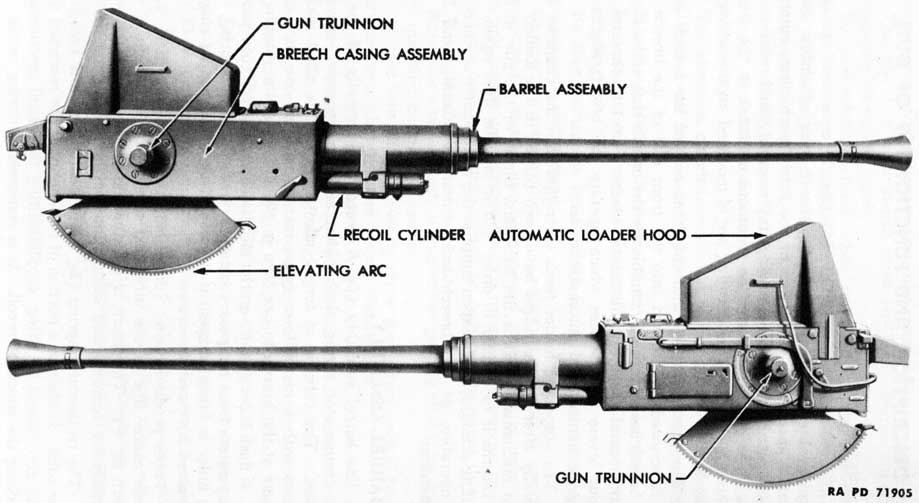
a. The 40-mm Automatic Gun M1 (fig. 5) consists of the barrel assembly, breech casing assembly, breech ring assembly, breech operating mechanism, a portion of the firing mechanism, automatic loader assembly, automatic loading tray assembly, and recoil mechanism. The gun is supported on trunnions mounted on the sides of the breech casing. The elevating arc is mounted on the under side of the breech casing.
b. The gun barrel fits into the front end of the breech casing and is screwed and locked into the front end of the breech ring. The breech casing forms a chamber for the breech ring, and a support for the barrel assembly, automatic loader, recoil mechanism, and various levers and devices which operate the breech mechanism, firing mechanism, and automatic loader.
c. The automatic loader feeds cartridges into the chamber automatically after the cartridges have been placed in the loader. The recoil mechanism absorbs the backward thrust of the gun in firing and returns it to battery in order that it may be fired again. The recoiling action of the weapon supplies the main source of energy for the operation of the breechblock, automatic loading, and firing mechanisms.
7. BARREL ASSEMBLY.
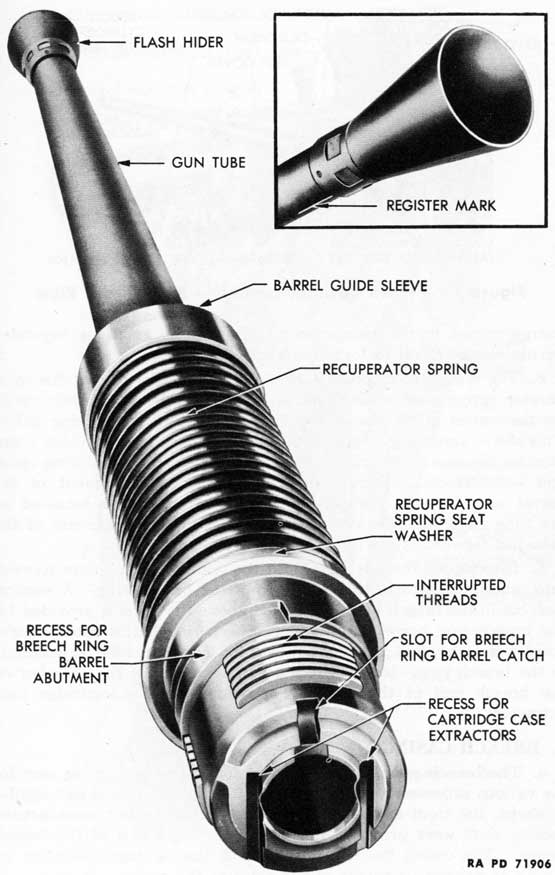
a. The barrel assembly (fig. 6) consists principally of the gun tube, recuperator spring, flash hider, and the necessary mounting devices. The tube is of forged alloy steel. It is rifled with 16 grooves with a nonuniform twist, increasing from one turn in 45 calibers at the breech to one turn in 30 calibers at the muzzle.
b. A flash hider (fig. 6) on the muzzle end of the gun tube protects the operators from temporary blindness from the flash of firing. The flash hider is funnel-shaped; it is screwed against a copper ring and is retained by three set screws.
c. Tubes produced after June 1943, have a register mark at the bottom center line of the tube, just to the rear of the flash hider (insert, fig. 6). This mark is for convenience in alining the barrel assembly for removal and installation, particularly in the dark.
d. The recuperator spring (fig. 6) is located near the breech end of the tube. It absorbs a portion of the energy of the rearward thrust of the gun caused by firing, supplementing the recoil mechanism in absorbing the shock of recoil. It is compressed during recoil. The
18
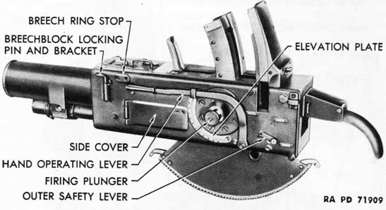
Figure 5 - 40-mm Automatic Gun M1 - Right and Left Sides
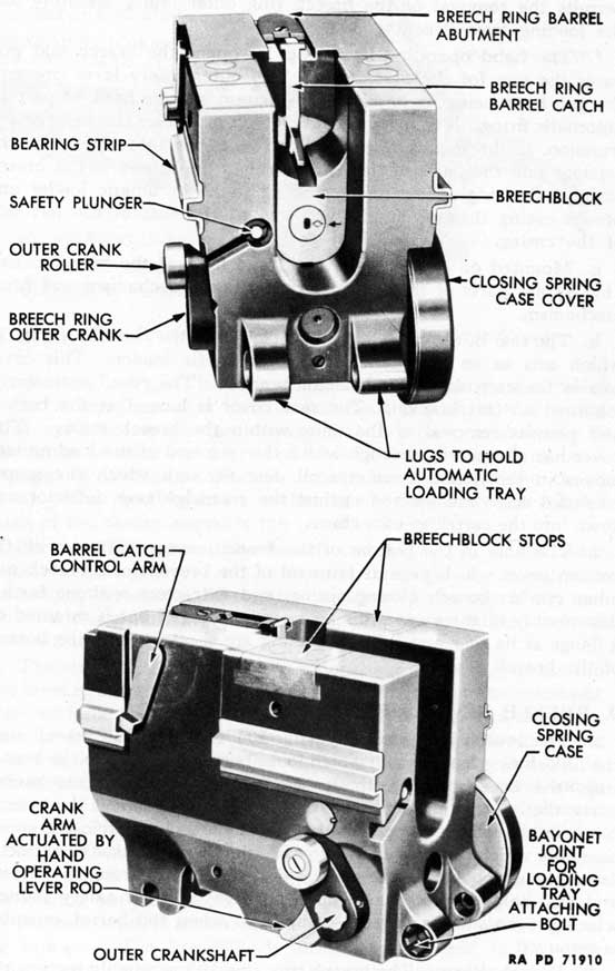
Figure 7 - Breech Casing Assembly - Right Front View
energy stored in the recuperator spring during recoil is expended during counterrecoil to force the gun back into battery.
e. The recuperator spring is held in compression against the recuperator spring seat washer and a surface inside the breech casing by the barrel guide sleeve and barrel guide sleeve locking collar. This sleeve centers the tube in the breech casing and provides a surface for the movement of the tube in the breech casing during recoil and counterrecoil. During the removal and replacement of the barrel assembly, the recuperator spring seat washer is retained on the tube by a shoulder or raised surface on the breech end of the tube just forward of the interrupted threads.
f. Interrupted threads (fig. 6) at the rear of the tube are screwed into mating threads in the front end of the breech ring. A vertical slot, cut in the breech end of the tube above the bore, is provided for the breech ring barrel catch. The breech ring barrel catch insures correct assembly and provides a means for locking the barrel assembly in the breech ring. Vertical recesses at each side of the chamber on the breech end of the tube are provided for the cartridge case extractors.
8. BREECH CASING.
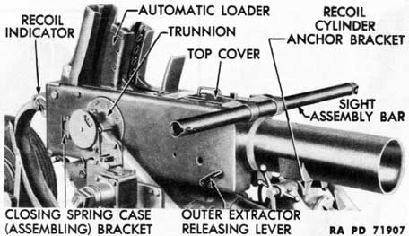
a. The breech casing (fig. 7) is the housing or supporting unit for the various subassemblies of the gun. The rear portion is rectangular in shape; the front end is tubular. On guns of earlier manufacture, cooling slots were provided in the tubular front end of the breech casing. The casing itself is supported in the carriage mounting by means of flanged trunnions at the sides of the casing. Four hinged or detachable covers give access to the interior of the casing.
b. The recoiling parts of the gun slide in recoil and counterrecoil
in the breech casing. The recuperator spring on the breech end of the gun is compressed in the tubular front portion of the casing against a surface inside the casing. The breech ring assembly is guided in its backward and forward movement in the casing by bearing strips which slide in channels on the inner sides of the casing (fig. 8). The recoil cylinder anchor bracket, beneath the tubular portion of the casing, supports the recoil cylinder.
c. On the right side of the breech casing (fig. 7) is the outer extractor releasing lever and the breech ring closing spring case (assembling) bracket. The latter is used in disassembling and assembling the breech ring closing spring after the assembly has been removed from the weapon.
d. The automatic loader fits into an opening in the rear of the top of the breech casing and is protected when not in use by the automatic loader hood and shield. The top cover, which is hinged to the upper surface of the casing near the front, provides a means for releasing the breech ring barrel catch which locks the barrel assembly to the breech ring, and also actuates the breech ring barrel catch control arm. Brackets on the front end of the top of the breech casing attach the sight supporting arm to the gun. The sights are described in paragraphs 91 and 92.
e. On the left side of the breech casing (fig. 9) are the breechblock locking pin and bracket, side cover, hand operating lever and front and rear latch brackets, elevation plate, outer safety lever, and firing plunger. The breechblock locking pin is used to lock the breech ring in the breech casing. It is inserted through a slot in the casing and a hole in the breech ring. The side cover has a cammed
23
inner surface which operates the breech ring outer crank assembly to lower the breechblock automatically during recoil. This cover also permits the removal of the breech ring outer crank assembly and the loading tray attaching bolt.
f. The hand operating lever (fig. 9) opens the breech and prepares the gun for the first round. The outer safety lever prevents the gun from being fired, allows single rounds to be fired, or permits automatic firing. The firing plunger which protrudes through the left trunnion, is the means of contact between the foot pedals on the carriage and the parts of the firing mechanism housed in the breech casing. Cartridge clips are ejected from the automatic loader and breech casing through an opening toward the rear of the left side of the casing.
g. Mounted on the inner left wall and floor of the breech casing (fig. 8) are parts of the hand operating lever mechanism and firing mechanism.
h. The rear of the breech casing is closed by the rear cover (fig. 9) which acts as an abutment for the automatic loader. This cover carries the cartridge case deflector bracket. The recoil indicator is mounted on this bracket. The rear cover is hinged at the bottom and permits removal of the units within the breech casing. This cover has an opening through which the rear end of the loading tray moves in recoil and counterrecoil, and through which the empty cartridge cases are ejected against the cartridge case deflector and down into the cartridge case chute.
i. The hole in the bottom of the breech casing is fitted with the bottom cover which permits removal of the breechblock, breech ring inner cranks, breech closing spring, and extractors without further disassembly of the gun. This cover is not hinged but is retained by a flange at its rear end. The elevating arc is attached to the bottom of the breech casing.
9. BREECH RING ASSEMBLY.
a. The breech ring assembly (fig. 10) includes: the breech ring; the breech ring barrel catch which locks barrel assembly to the breech ring; the breechblock with its assembled percussion mechanism parts; the breech ring outer crank assembly which moves the breechblock up and down to open and close the breech; the closing spring assembly which supplies energy to raise the breechblock; the extractor assembly which ejects the empty cartridge cases from the breech and also holds the breech in open position; and the safety plunger which prevents the gun from being fired when the barrel assembly is removed.
b. Breech Ring. The breech ring (fig. 10) is roughly rectangular in shape. It is threaded internally at the front to receive the tube.
24
Figure 10-Breech Ring Assembly
25
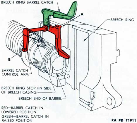
Figure 11-Breech Ring Barrel Catch
It has an opening from top to bottom in the center in which the breechblock slides up and down. Stops, mounted in the upper surface of the breech ring, limit the upward movement when the breechblock closes. The upper rear central portion of the breech ring is cut away in U-shape to provide access for loading and unloading. Two lugs at the rear provide a bayonet joint for the loading tray attaching bolt. Bearing strips on the sides of the breech ring slide in channels on the inside walls of the breech casing when the breech ring is carried backward and forward in recoil and counterrecoil. The extractor spindle arm protrudes from the lower right side of the breech ring.
c. Breech Ring Barrel Catch.
(1) The breech ring barrel catch, when lowered, prevents the barrel assembly from rotating to a position where it could be removed from the breech ring. This catch (red in fig. 11) locks the barrel assembly in the breech ring by engaging a slot in the breech end of the tube. The pointed rear end of the catch guides the cartridge into the chamber.
(2) Two lugs (A, fig. 11) at the top rear of the catch ride in a groove in the top cover. When the top cover is opened, this action lifts the catch from its slot in the tube (green in fig. 11) and permits the tube to be rotated and removed from the breech ring.
(3) As the catch is raised, the barrel catch control arm is rotated
26
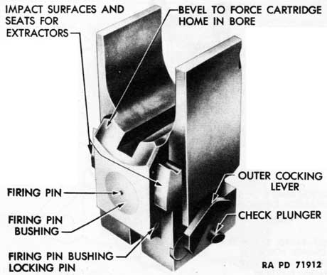
Figure 12-Breechblock Assembly-Front View
to a position where its toe (B, fig. 11) engages the breech ring stop. This locks the breech ring in the casing and prevents it from slipping to the rear when the barrel assembly is removed.
d. Breechblock Assembly.
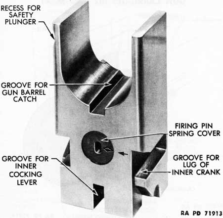
(1) The breechblock (figs. 12 and 13) is roughly rectangular in shape. A U-shaped portion of the upper center is cut away to permit loading and unloading of the weapon when the breechblock is lowered (breech open). A groove is cut in the lower part of the "U" for the finger of the breech ring barrel catch. A square projection on the front surface of the block is beveled at the top to force the cartridge case home as the breechblock slides upward to closed position.
(2) Impact surfaces and hook-shaped seats are provided at the sides of the front of the breechblock for the cartridge case extractors. Horizontal grooves in the sides of the breechblock are provided for the lugs of the breech ring inner cranks which force the breechblock downward and upward to open and closed positions.
(3) The outer cocking lever is located on the lower left side of the breechblock. Its shaft runs from side to side through a bore near the bottom of the breechblock. A groove is cut in the bottom from front to rear for the inner cocking lever which is mounted on the splined shaft of the outer cocking lever. The check plunger occupies another bore which extends from side to side near the bottom of the breechblock.
27
Figure 13-Breechblock Assembly-Rear View
(4) The breechblock is bored from front to rear. This bore is closed at the front by the firing pin bushing (fig. 12) and at the rear by the firing pin spring cover (fig. 13). This bore houses the firing pin and the firing pin spring. Some breechblocks have a solid front face, no bushing, only a hole for the tip of the firing pin.
(5) The breechblock is recessed on the upper left rear side to receive the breech ring safety plunger (fig. 13). The operation of the safety plunger is described in paragraph 9 g.
e. Breech Ring Outer Crank Assembly.
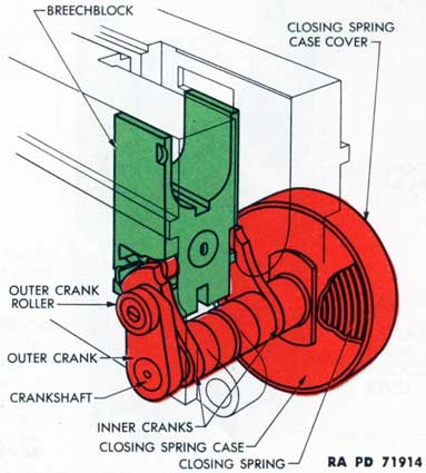
(1) The breech ring outer crank assembly raises and lowers the breechblock to closed and open positions. This mechanism consists of the breech ring outer crank, outer crank roller, outer crankshaft, left inner crank, crankshaft collar, right inner crank, and the closing spring assembly. The latter consists of the closing spring, closing spring case, and closing spring case cover (fig. 14).
(2) When the outer crank is actuated, either by the hand operating lever (hand operation) or the cam surface on the inside of the side operating cover (automatic operation), the crankshaft is rotated. This causes the inner cranks to lower the breechblock by means of lugs which bear on the surfaces of the grooves near the bottom of the breechblock. The rotation of the crankshaft also winds up the closing spring, storing energy which is used to rotate the crankshaft assembly to lift the breechblock and close the breech.
28
Figure 14-Closing Spring Raising Breechblock
Figure 15-Left and Right Breech Ring Inner Cranks
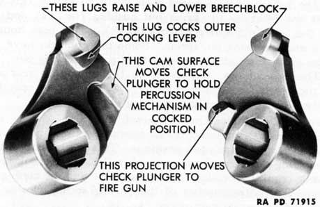
(3) The right and left inner cranks (fig. 15) not only bear lugs which raise and lower the breechblock, but another lug on the left inner crank operates the outer cocking lever, and a cam surface on the left inner crank and a projection on the right inner crank move the check plunger (par. 12 f).
29
Figure 16-Extractor Releasing Lever Assembly
Figure 17-Extractors-Released by Cartridge Case
30
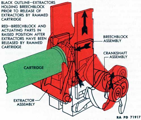
f. Extractor Assembly.
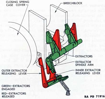
(1) The cartridge case extractor assembly serves two purposes: It holds the breechblock in open position until released by the outer extractor releasing lever (hand operation) or by the insertion of a round into the breech (automatic operation); it releases and ejects the empty cartridge cases from the firing chamber of the gun. The extractor assembly consists of two extractors, extractor spindle, extractor spindle arm, inner and outer extractor releasing levers, spring, and spring stud (fig. 16).
(2) When the breechblock is lowered to open the breech, the extractors are tipped backward until their hooked ends are engaged in seats on the front of the breechblock (green in fig. 16). In their engaged position, they hold the breechblock in open position. The breechblock is released manually (red in fig. 16) by rotating the outer extractor releasing lever to the rear. The breechblock is released automatically when a cartridge case is rammed into the chamber, the rim of the cartridge case rotating the extractors from their seats on the breechblock as the rim of the cartridge case drives them forward (fig. 17).
(3) The extractors release the cartridge case from the chamber by reversing the procedure illustrated in figure 17. As the extractors are rotated to the rear to engage the breechblock and hold it in open position, their upper lips press on the rim of the cartridge case with such force as to extract the case from the firing chamber and eject it through the breech casing, and out the cartridge chute.
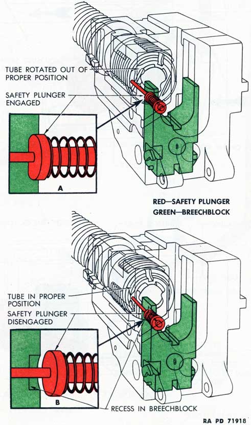
g. Breech Ring Safety Plunger.
(1) The rear end of the breech ring safety plunger protrudes from a depression in the left side of the rear of the breech ring (figs. 10 and 18). This device prevents the gun from being fired when the tube is out of its proper position or removed. The safety plunger assembly consists of the safety plunger, compression spring, and safety plunger spring seat.
(2) The safety plunger extends through a bore in the breech ring to contact the breech face of the tube. It is fitted with a tubular seat which fits a depression in the lowered breechblock (A, fig. 18) when the tube is out of its proper position and the compression spring of the safety plunger drives the plunger forward. Thus it locks the breechblock in its down position, putting the breech mechanism out of action. This plunger is pressed backward and its seat is held out of the depression in the breechblock when the barrel assembly is properly assembled in the breech ring (B, fig. 18).
10. BREECH OPERATING MECHANISM.
a. The breech operating mechanism consists of the various devices for operating the breechblock which are attached to the breech ring,
31
Figure 18-Action of Breech Ring Safety Plunger
32
Figure 19-Cam Action of Outer Crank and Side Cover
33
Figure 20-Hand Operating Mechanism and Hand Operating Device
34
together with other parts which are attached to the breech casing. The latter are: the cam surface on the inside of the side cover which engages the outer crank assembly to lower the breechblock automatically; the hand operating lever and mechanism which prepare the gun for the first round by opening the breech and actuating the hand operating device of the automatic loader assembly; and the extractor releasing lever assembly which releases the extractors and permits the breech to be closed manually.
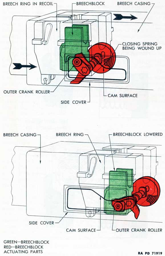
b. Side Cover. The inner side of the side cover has a cam surface which is engaged by the roller of the breech ring outer crank during recoil of the weapon (fig. 19). This engagement causes the outer crank to be rotated, rotating the inner cranks, and causing them to force the breechblock downward. The breech is closed by releasing the extractors (par. 9 f).
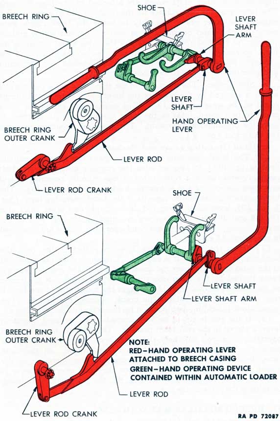
c. Hand Operating Lever and Mechanism.
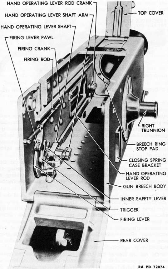
(1) The hand operating mechanism opens the breech manually (red in fig. 20). It also actuates the rammer cocking lever shaft assembly and the feed roller catch release spindle assembly (hand operating device) of the automatic loader (green in fig. 20). The hand operating mechanism consists of the hand operating lever (figs. 9 and 20), lever shaft, lever rod, lever crank, and lever shaft arm (figs. 8 and 20), all of which are mounted on the left wall of the breech casing. The parts of the hand operating device are described in paragraph 17 c.
(2) When the hand operating lever is pulled to the rear, the hand operating lever shaft is rotated. This shaft pulls the front end of the hand operating lever rod downward and to the rear, the motion being limited by the hand operating lever rod crank. A projection on the hand operating lever rod engages the lower arm of the breech ring outer crank and rotates the crank, opening the breech. The breechblock is held in open position by the action of the extractors.
(3) If the gun is not to be fired immediately, the hand operating lever is placed in the rear latch bracket. The projection on the hand operating lever rod will hold the lower arm of the outer crank in place, preventing the breechblock from being raised. At the same time, the rear end of the lever rod prevents the operation of the breech casing firing mechanism. When the hand operating lever is returned to its forward position (fig. 9), the breechblock is freed, permitting the firing of the gun.
11. BREECH MECHANISM FUNCTIONING.
a. The breechblock is held in the raised or closed position against the breechblock stops of the breech ring by the tension of the breech ring closing spring. The breech may be opened and closed by hand,
35
or opened automatically by the action of recoil and closed by the ramming of a cartridge.
b. Manual Operation.
(1) To OPEN BREECH.
(a) When the hand operating lever is lifted and pulled to the rear as far as it will go, the lever rotates the hand operating lever shaft. The shaft pulls the front end of the hand operating lever rod downward and to the rear. The movement of the rod is controlled by the hand operating lever crank which pivots in the breech casing. A projection on the rod engages the lower arm of the breech ring outer crank, rotating it in a counterclockwise direction.
(b) The outer crank rotates its shaft, inner cranks, and closing spring case, placing the closing spring under tension. Lugs on the inner cranks bear on the surfaces of the grooves in the sides of the breechblock and force the breechblock downward into the fully open position.
(c) As the breechblock descends, impact surfaces on the front of the breechblock strike the toes of the extractors, rotating them to the rear. If there is a cartridge case in the chamber of the weapon, the lips of the extractors press against its rim, extract it from the firing chamber, and eject it. Hand operation will not always accomplish complete extraction and ejection because of the slowness of the operation. The extractors come to rest directly above the hook-shaped notches in the breechblock into which the hooks of the extractors fit.
(d) When the hand operating lever is moved forward, the outer crank is released and the closing spring tends to assert itself. It raises the breechblock until the hook-shaped notches on the front face of the breechblock are engaged by the hook-shaped projections on the extractors. The breechblock is retained in the open position.
NOTE: The percussion mechanism in the breechblock starts to cock prior to the downward movement of the breechblock. A fully cocked position is reached at the point of initial downward movement of the breechblock (par. 12 g).
(2) To CLOSE BREECH.
(a) When the outer extractor releasing lever is pressed rearward, the inner extractor releasing lever is rotated. This lever engages and rotates the extractor spindle arm and extractor spindle, moving the extractors forward. The extractors are withdrawn from the hook-shaped notches on the front face of the breechblock. The breechblock is now free to be raised by the action of the closing spring, provided the hand operating lever is in its forward position.
(b) Under the tension of the closing spring, the inner cranks rotate with the outer crankshaft, raising the breechblock to its closed position against the breechblock stops. After the breechblock is raised, the inner cranks continue to move and their lugs move along the inclines at the rear of the horizontal grooves in the breechblock
36
until they reach a position where they support the breechblock in such
manner that the weight of the breechblock cannot rotate the inner cranks.
c. Automatic Operation.
(1) To OPEN BREECH. When the weapon recoils on firing, the roller on the outer crank runs along the cam formed in the inner surface of the side cover. The cam rotates the outer crank and the action is the same as for opening the breech by hand (subpar. h (1), above) except that the extractors hook on their engaging notches on the breechblock as the gun counterrecoils instead of when the hand operating lever is folded forward.
(2) To CLOSE BREECH. The cartridge moving forward by the action of the rammer (par. 16) engages the extractors and rotates them forward, thereby releasing the breechblock. The closing spring asserts itself and the action is the same as for closing the breech by hand.
12. FIRING MECHANISM.
a. The gun fires automatically when the breechblock has reached the fully closed position. The percussion mechanism, which actually fires the gun by striking the primer of the cartridge, is housed in the breechblock. The action which fires the piece is the release of the loading rammer which rams the cartridge into the chamber, tripping the extractors, and permitting the breechblock to raise to closed position. Either of two firing pedals on the carriage may be depressed to release the rammer.
b. Means are provided to prevent the gun from being fired, to allow single rounds to be fired, or to permit automatic firing. Means are also provided to stop automatic loading and firing when only one cartridge remains in the feed guides of the automatic loader.
c. The firing mechanism is composed of two principal groups of parts, those attached to the carriage and those attached to or housed in the breech casing. These groups make contact with each other outside the left trunnion of the breech casing.
d. The parts of the firing mechanism attached to the carriage consist of the firing pedals, linkage, and attachments. Their function is to provide means on the carriage for releasing the parts of the firing mechanism housed in the breech casing. The parts of the firing mechanism on the carriage are described in paragraph 29.
e. The parts attached to or housed in the breech casing consist of the percussion mechanism in the breechblock, the rammer catch and check levers of the automatic loader, and the breech casing firing mechanism attached to the inside left wall and floor of the breech casing. The percussion mechanism is automatically cocked and the
37
Figure 21-Firing Pin-Cocked Position
rammer is drawn back to firing position when the hand operating lever is pulled all the way backward or when the gun fully recoils and counterrecoils after firing.
f. Percussion Mechanism.
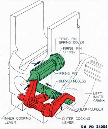
(1) The percussion mechanism housed in the breechblock consists of the firing pin, firing pin spring, inner cocking lever, outer cocking lever, check plunger, and check plunger spring. The outer cocking lever and the check plunger are actuated by lugs and cammed surfaces on the breech ring inner cranks (fig. 15).
(2) The firing pin has a flat-nosed point and a cup-like rear end (fig. 21). When held in cocked position by the inner cocking lever, the firing pin spring is compressed against the firing pin spring cover at the rear of the firing pin bore in the breechblock. When released, it is driven forward by the spring and its point protrudes through the hole in the center of the firing pin bushing to strike the primer of the cartridge (fig. 22).
(3) The inner cocking lever is an angular piece mounted in a slot in the base of the breechblock and splined on the shaft of the outer cocking lever. One end is ridged; the other is notched; its hub is splined. The outer cocking lever has an angular arm and a splined shaft. The latter causes the inner cocking lever to move with it. The shaft fits into a bore near the front and bottom of the breechblock. The arm of the outer cocking lever rests near the horizontal
38
Figure 22-Firing Pin-Fired Position
groove on the left side of the breechblock where it is contacted by a lug on the left breech ring inner crank.
(4) The check plunger is a shaft with two diameters. The end with the smaller diameter has a beveled face; the other end has a cam surface head. The head has flat sides to prevent the plunger from turning in its bore. The check plunger protrudes from both sides of a bore through the lower central portion of the breechblock. The check plunger spring, which fits over the smaller diameter, tends to drive the plunger to the right. A recess is cut in the larger diameter of the plunger. The function of the check plunger is to retain and release the inner cocking lever which retains and releases the firing pin. The plunger is actuated by the breech ring inner cranks.
g. Percussion Mechanism Functioning.
(1) To COCK.
(a) When the hand operating lever is pulled backward or the gun recoils, the breech ring outer crank is rotated, rotating the inner cranks and lowering the breechblock. The broader of the stepped lugs on the left inner crank (fig. 15) engages the outer cocking lever, rotating it and the inner cocking lever. The ridge end of the inner cocking lever bears against the shoulder of the firing pin, forcing it to the rear and compressing the firing pin spring (fig. 21). The beveled projection on the right inner crank is moved from contact
39
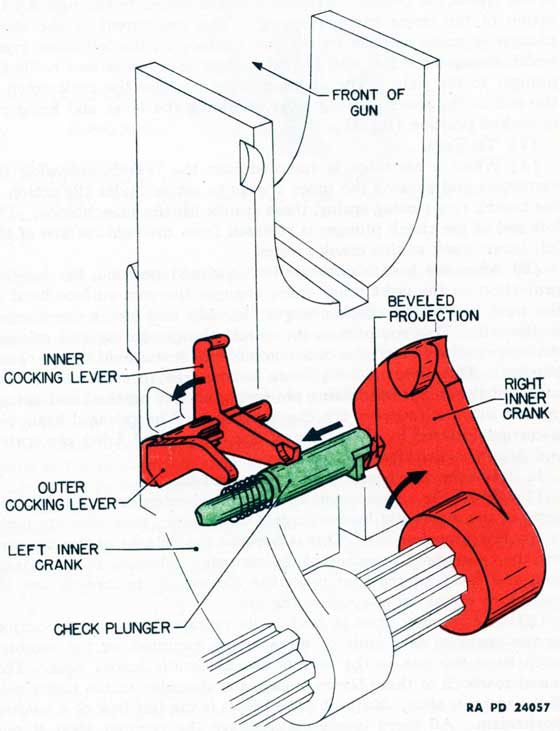
Figure 23-Check Plunger-Release by Right Inner Crank
40
with the end of the plunger, freeing the plunger to be forced to the right when released.
(b) When the inner cocking lever has been rotated downward through the recess in the check plunger until its notched end is clear of the recess, the plunger is released and is forced to the right by the action of the check plunger spring. This movement of the check plunger is made positive by the cam surface on the left inner crank which engages the left end of the plunger and forces and holds the plunger to the right. The check plunger engages the cock notch in the end of the inner cocking lever, retaining the lever and firing pin in cocked position (fig. 21).
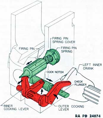
(2) To FIRE.
(a) When a cartridge is rammed into the breech, releasing the extractors and causing the inner cranks to rotate under the action of the breech ring closing spring, these cranks lift the breechblock. The left end of the check plunger is released from the cam surface of the left inner crank as this crank rotates.
(b) After the breechblock arrives in closed position, the beveled projection on the right inner crank engages the cam surface head at the right end of the check plunger (fig. 23) and forces the plunger to the left. This compresses the check plunger spring and releases the inner cocking lever, the cock notch of which was held by the check plunger. The inner cocking lever is now free to rotate under the action of the compressed firing pin spring and its notched end swings upward into the recess in the check plunger. The released firing pin is carried forward by the action of the compressed firing pin spring and fires the cartridge (fig. 22).
h. Rammer Catch and Check Mechanisms.
(1) While the rammer catch and check mechanisms (fig. 38) are parts of the automatic loader control mechanism, they also are parts of the firing mechanism. This is because the release of the rammer and the consequent ramming of the cartridge, releasing of the extractors, and firing of the gun upon the closing of the breech are all operations in the firing cycle of the gun.
(2) The rammer shoe is held in its rearward or cocked position by the upthrust rear ends of three levers mounted on the rammer catch lever axis pin in the rear of the automatic loader base. The raised rear ends of these levers engage the shoulder on the under side of the rammer shoe. Each of these levers is the last link of a holding mechanism. All three levers may engage the rammer shoe at one time; or any one or two of them may prevent the rammer from moving forward. All must be depressed before the rammer shoe is released.
(3) These mechanisms are: the automatic catch and release mechanism (par. 17 d) which insures that the rammer cannot be
released until the gun reaches the end of counterrecoil; the feed control check and release mechanism (par. 17 e) which can be set to stop automatic loading and firing when only one cartridge remains in the feed guides of the loader; and the firing mechanism check and release mechanism (par. 17 f) which is controlled by the safety lever.
i. Breech Casing Firing Mechanism.
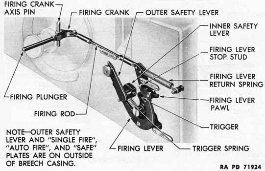
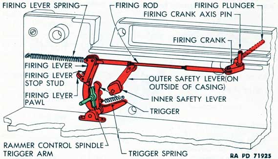
(1) The breech casing firing mechanism (fig. 24) consists of the parts of the firing mechanism which are mounted on the left wall and floor of the breech casing (fig. 24). It includes the safety lever and its mechanism. The breech casing firing mechanism converts the movement of the firing plunger in the left gun trunnion into movement which releases the rammer and fires the gun. The firing plunger is actuated by depressing either of the firing pedals on the carriage.
(2) The firing lever (fig. 24) is roughly U-shaped. It is pivoted on a bracket fastened to the floor of the breech casing. Its longer upper arm is pulled forward by the firing rod and crank when the firing plunger is pressed inwardly by the action of depressing either of the firing pedals. It is returned to its normal position by the firing lever return spring.
(3) The firing lever pawl (fig. 24) is pivoted between lugs on the rear of the longer arm of the firing lever. The trigger is located in the "U" of the firing lever and pivoted on a pin in the left wall of the breech casing. When the firing lever is pulled forward, the firing lever pawl contacts the trigger and rotates the trigger on its axis pin. The trigger rotates the rammer control spindle trigger arm of the automatic loader to release the rammer shoe and fire the gun.
42
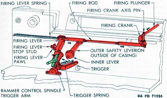
Figure 25-Firing Mechanism-"Single Fire"-Prior to Firing
When rotation has stopped, the trigger is returned to its normal position against its stop on the firing lever shaft by the trigger spring and the left rammer check lever plunger spring.
(4) The firing lever pawl is tripped by the firing lever stop stud to release the trigger and produce "single fire" action. The rotation of the trigger is controlled by the position of the inner safety lever.
(5) The outer safety lever (fig. 24) is mounted toward the rear on the outer left side of the breech casing. Its head or handle has a spring-loaded plunger which permits it to be locked in holes in either of three positions. Movement of the lever rotates the cam-faced inner safety lever, the surfaces of which control the action of the trigger. In the rearmost or "SAFE" position of the outer safety lever, the gun is prevented from being fired. The central or "AUTO FIRE" position of the lever permits automatic firing. The foremost or "SINGLE FIRE" position of the lever allows single rounds to be fired.
(6) SAFE. With the outer safety lever in "SAFE" or rearward position, the inner safety lever is turned so that its cammed surface restricts the rotation of the trigger to such an extent that the trigger cannot move sufficiently to rotate the rammer control spindle trigger arm and release the rammer.
(7) SINGLE FIRE. With the outer safety lever in "SINGLE FIRE" or forward position, the inner safety lever is rotated until it is completely out of contact with the trigger (fig. 25). When the firing lever is pulled forward by the firing rod, the firing lever pawl rotates the
43
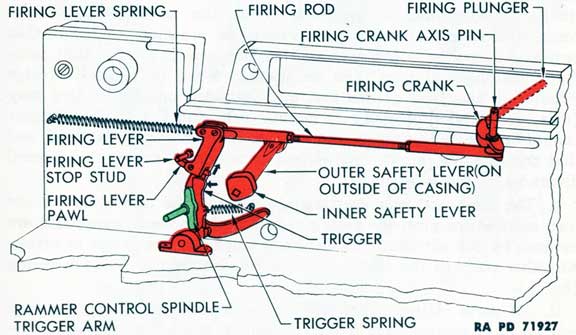
Figure 26-Firing Mechanism-"Single Fire"-Firing
Figure 27-Firing Mechanism-"Single Fire"-Release After Single Fire
trigger to fire one round (fig. 26). This is done by rotating the
rammer control spindle trigger arm which releases the left rammer
check lever from the rammer shoe. Then the firing lever pawl is
tripped upon contacting the firing lever stop stud and the trigger is
released and snapped back to its original position by the trigger
spring (fig. 27).
(8) AUTOMATIC FIRE. With the outer safety lever in "AUTO
FIRE" or central position, the inner safety lever is rotated sufficiently
44
to prevent the trigger from being rotated enough to be released by the firing lever stop stud. It does, however, permit the trigger to rotate far enough to rotate and hold the rammer control spindle trigger arm and depress the left rammer check lever. Uninterrupted firing will continue until the firing pedal is released or the supply of ammunition in the automatic loader is insufficient to operate the gun.