a. GUN IS TOO FAST IN RECOIL AND TOO SLOW IN COUNTER-RECOIL. This condition may be caused by a malfunction of the recoil cylinder (par. 36) or by a broken or weak recuperator spring. If the recoil cylinder is functioning properly, check condition of the recuperator spring (par. 30 b) and replace, if necessary (pars. 29 and 31). The locking collar must be tight and securely locked (par. 31 e).
b. GUN Is Too SLOW IN RECOIL AND FAILS TO RETURN TO BATTERY POSITION. This condition may be caused by a burred, damaged, or loose barrel guide sleeve and locking collar. Make sure that the collar is tight and securely locked (par. 31 e). If the sleeve is only slightly burred, dress and polish the surface. Replace a badly damaged sleeve or locking collar (pars. 29 and 31).
c. TUBE WILL NOT LOCK SECURELY IN BREECH RING. This is evidenced by difficult operation of the top cover of the breech casing. If the tube is not correctly positioned in the breech ring, the barrel catch of the top cover will not engage the slot in the tube, causing difficulty in opening or closing the cover. This condition may be caused by dirt or accumulation of lubricant in the breech ring or on the threaded part of the tube or by damaged threads. To remedy, remove the tube, clean the threads, and remove minor abrasions. Be careful to remove only enough metal to restore the original contour of the threads. A badly worn or damaged tube should be replaced (pars. 29 and 31).
29. Disassembly
a. Remove the barrel assembly (TM 9-251 or TM 9-252).
b. Remove three screws that retain the flash hider and unscrew the flash hider, using the flash hider wrench-41-W-1480-50 (fig. 10). Remove the two gaskets.
68
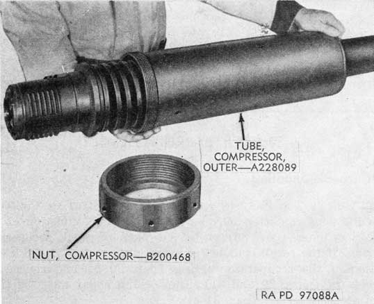
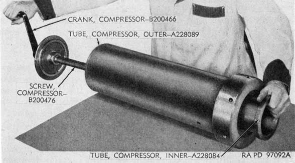
Figure 21. Installing outer compressor tube over recuperator spring.
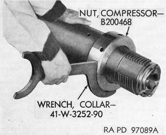
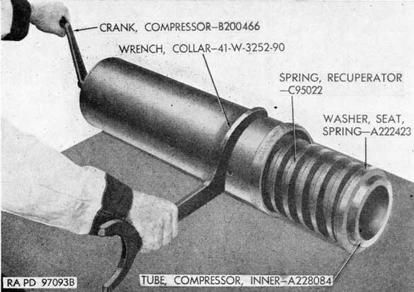
Figure 22. Installing compressor nut on compressor tube.
c. Install the outer tube of the screw-type recuperator spring compressor - 41-C-2555-800 (fig. 7) over the recuperator spring with the threaded end of the outer compressor tube toward the breech end of the gun tube (fig. 21).
d. Install the compressor nut of the compressor, screwing it onto the threaded end of the compressor tube with the hook spanner portion of the recuperator spring collar wrench -41-W-3252-90 (figs. 10 and 22). Tighten the nut securely.
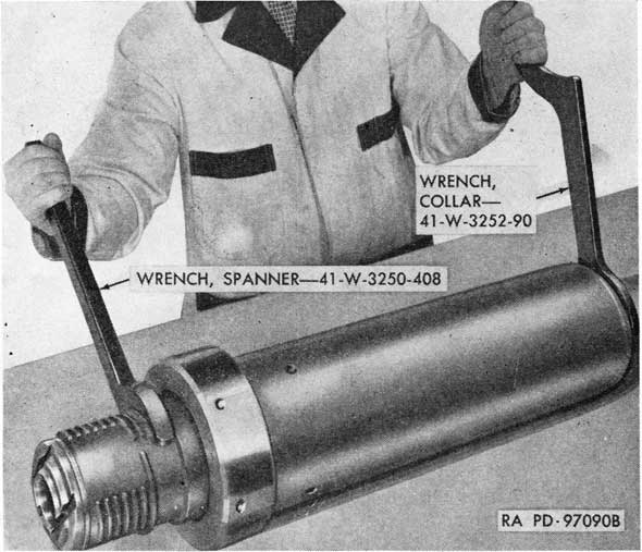
e. Loosen the two set screws on the locking collar. Unscrew the locking collar with the face spanner portion of the recuperator spring collar wrench - 41-W-3252-90 (fig. 10), while holding the breech end of the tube with the hook spanner wrench -41-W-3250-408 (figs. 11 and 23). Remove the locking collar.
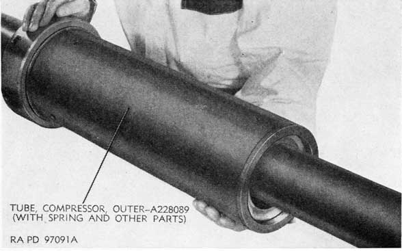
f. Remove the compressor tube, within which the recuperator spring and other parts are confined, by pushing it forward and off the muzzle end of the tube (fig. 24). The spring compressor case (fig. 7) provides a convenient means of carrying the compressor tube and parts.
70
Figure 24. Removing compressor tube with recuperator spring.
g. Insert the inner tube of the compressor through the compressor nut on the outer tube and into the spring, with the flanged end of the inner tube against the spring seat washer (fig. 25).
h. Install the screw of the compressor through the opposite end of the tube (fig. 25) and tighten the screw enough to release spring pressure on the compressor nut on the outer compressor tube. Remove the compressor nut.
Figure 25. Installing inner compressor tube and screw.
71
Figure 26. Releasing the recuperator spring.
i. Loosen the screw of the compressor (fig. 26) until the spring tension is fully released and remove the screw from the tube. Hold the compressor tube with the collar wrench, if necessary.
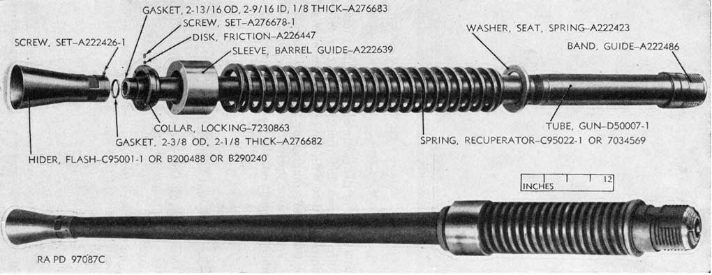
j. Remove the outer compressor tube and remove the barrel guide sleeve, recuperator spring, and spring seat washer from the inner tube. All parts of the barrel assembly are shown in figure 27.
30. Repair, Overhaul, and Rebuild
a. Clean the parts of the barrel assembly and inspect for external cracks or damage. Check parts (gun M1) for surface treatment (par. 27).
b. Check the recuperator spring for breaks or cracks and measure for set. Minimum free length of the round cross-section spring should be 36 inches and minimum free length of the square cross-section spring should be 34 5/16 inches; if free length is less, replace the spring. If on check firing, the gun recoils more than 8.3 inches and the recoil cylinder is found to be functioning properly, check the force exerted by the spring. Either type of spring should exert 1,800 pounds, or more, pressure when it is compressed to a length of 13 inches.
72
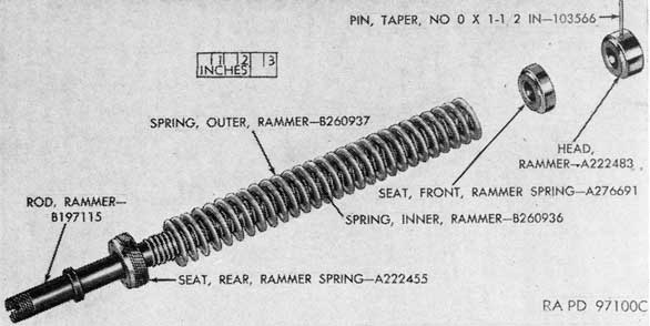
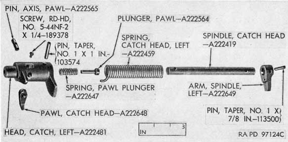
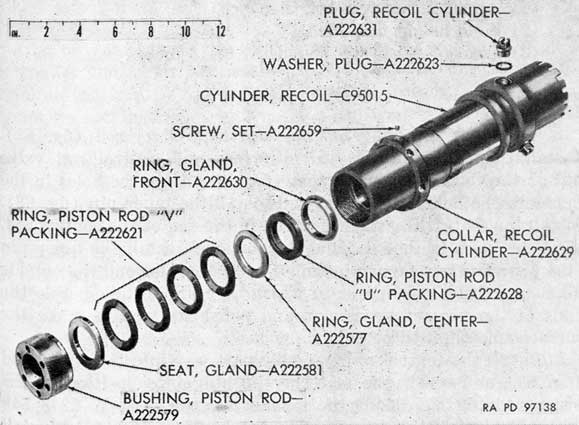
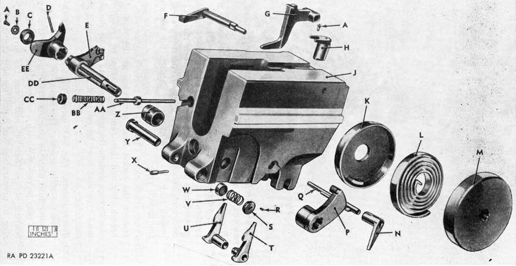
Figure 27. Parts of barrel assembly.
73
c. Look for damaged threads on the locking collar and the flash hider and check the surface of the barrel guide sleeve for smoothness. Remove all rough spots. Remove burs from threads.
d. Examine the tube for damaged threads and external pits and rust. Remove all rust and corrosion and clean the pits.
e. Refer to TB 9-1860-2 for information on inspection and evaluation of bores.
f. Report to the Chief of Ordnance, Washington 25, DC, Attention: ORDFM - Weapons Section, giving full information, bore impressions, and pull-over-gage readings of the tubes which, after inspection, are questionable as to serviceability and cannot be classified by a competent inspector. (Serviceability of tubes for oversea shipment is governed by TB ORD 385 which tabulates the allowable number of rounds fired.) Retain for use within the zone of interior, as instructed by the Chief of Ordnance, tubes which have been fired more rounds than allowed for oversea shipment TB ORD 385 but are not otherwise unserviceable.
31. Assembly
a. Install the barrel guide sleeve and the recuperator spring in the outer compressor tube. Install the spring seat washer over the inner compressor tube, against the flange of the tube.
b. Insert the inner tube of the compressor in the recuperator spring and through the threaded end of the outer tube. Install the screw of the compressor and compress the spring until it is possible to thread the compressor nut on the compressor tube (fig. 26).
c. Install the compressor nut on the compressor tube and tighten with the spring collar wrench - 41-W-3252-90 (figs. 10 and 22). Then remove the screw and the inner compressor tube (fig. 25).
d. Install the outer compressor tube with assembled parts on the gun tube, with the compressor nut toward the breech end of the tube (fig. 24).
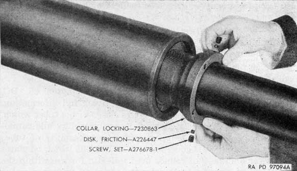
e. Install the barrel guide sleeve locking collar (fig. 28) and tighten the collar with the face spanner portion of the recuperator spring collar wrench while holding the breech end of tube with the hook spanner wrench - 41-W-3250-408 (fig. 23). Install the two set screws with disks in the locking collar and tighten the screws securely.
f. Remove the compressor nut from the compressor tube, using the recuperator spring collar wrench - 41-W-3252-90 (fig. 22). Remove the compressor tube from the barrel assembly (fig. 21).
74
Figure 28. Installing the barrel guide sleeve locking collar.
g. Install the two gaskets and the flash hider at the muzzle end of the tube. Tighten the flash hider with the flash hider wrench - 41-W-1480-50 (fig. 10) and aline the screw holes in the hider with those in the tube. Install the three screws.
h. Install barrel assembly (TM 9-251 or TM 9-252).
Section II. AUTOMATIC LOADER ASSEMBLY
32. Trouble-Shooting
a. LOADER FAILS TO FEED CARTRIDGES INTO THE FIRING CHAMBER. This is the most common malfunction of the automatic loader assembly. Such failure may be caused by a broken rammer spring, broken rammer lever springs, or obstructions in the loader. To remedy, remove the loader and loading tray and replace the defective parts in the tray assembly (pars. 33 b and 35 i).
b. FEED ROLLERS FAIL TO ROTATE. The feed rollers may fail to rotate because of a broken feed roller catch head, catch arm, or catch spring, a sheared taper pin in the feed roller shafts, or worn bushings in the rollers. To correct, remove and disassemble the loading tray and replace defective parts (pars. 33 b and 35 0.
c. FEED CONTROL MECHANISM FAILS To FUNCTION PROPERLY. Failure of the feed control mechanism to function properly may be caused by loose or worn screws which retain the cam and the feed control arm on the feed control spindle in the rear guide.
The loader need not be removed to correct this condition; on the loader for gun M1, or left loader for dual gun M2, remove the right rail (par. 33c) and tighten or replace the screws; on the right loader for dual gun M2, remove the left rail (par. 33c) to gain access to the screws.
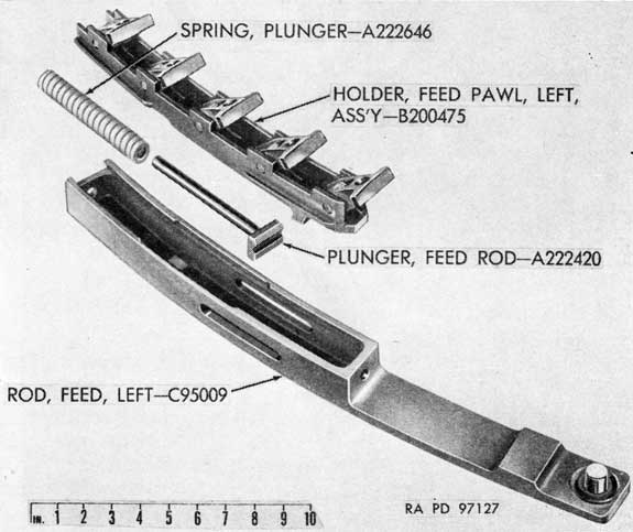
d. FEED ROD ASSEMBLY OPERATIONS FAULTY. Faulty operation of the feed rod assembly may be caused by broken feed pawl springs, pins, or rollers, worn or damaged feed rod rollers, or a broken feed rod plunger spring. To correct, remove the loader assembly and remove the loading tray (par. 33b). The feed rod rollers may be removed and installed without further disassembly of the loader. If the trouble is caused by defective parts in the feed rod assemblies, these assemblies must be removed from the loader, disassembled, and new parts installed (pars. 33 and 35).
e. STOP PAWLS FAIL TO HOLD CARTRIDGES PROPERLY. If the stop pawl assemblies fail to hold the front end of the cartridge down properly, the pawl holder assemblies may be removed from the frames without removing the loader from the gun. Remove each holder from its frame (par. 33f (4)). Remove the broken pins, rollers, springs, and pawls from the holder and replace with new parts (pars. 33 f (5) and 35 e (3)). Install the holder in the frame (par. 35 e (4)).
33. Disassembly
a. GENERAL.
(1) Very little disassembly of the automatic loader may be performed without removing the assembly from the gun; refer to TM 9-251 or TM 9-252 for removal of loaders. The stop pawl assembly and feed control thumb lever assembly may be removed and installed with the loader mounted on the gun.
(2) Complete disassembly of the loader is described in this manual. However, complete disassembly is seldom required, and good judgment must be exercised in order to reduce disassembly operations to a minimum while making necessary replacement of parts. Figures 29, 30, and 31 are intended to serve as an aid in this respect.
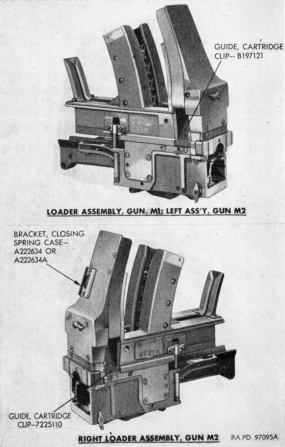
(3) Unless otherwise noted, illustrations in this section are of the loader assembly for the gun M1 or the left loader for the gun M2. Both loader assemblies are serviced in the same manner. Some parts of the right loader of gun M2 are symmetrically opposite to corresponding parts in the left loader of gun M2 or to those in the loader of gun M1.
79
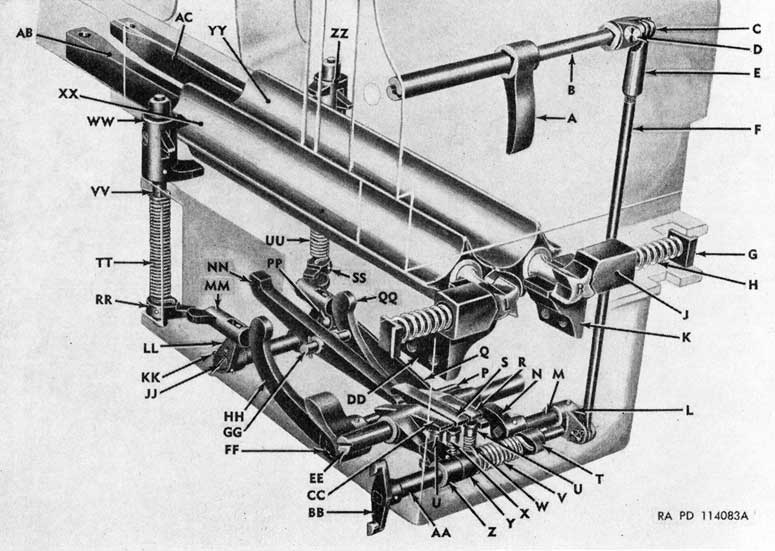
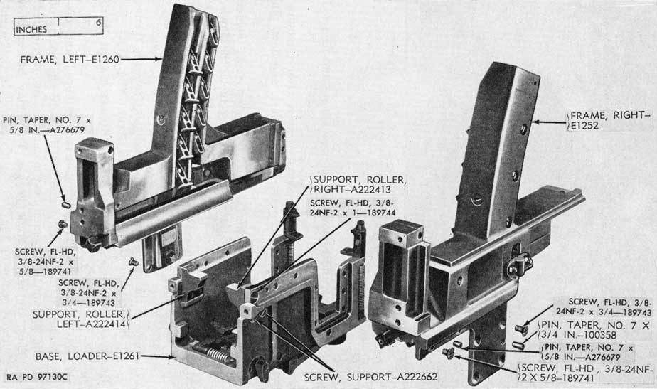
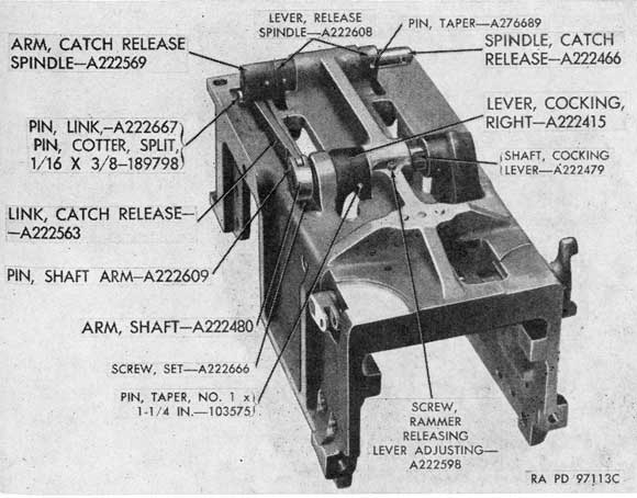
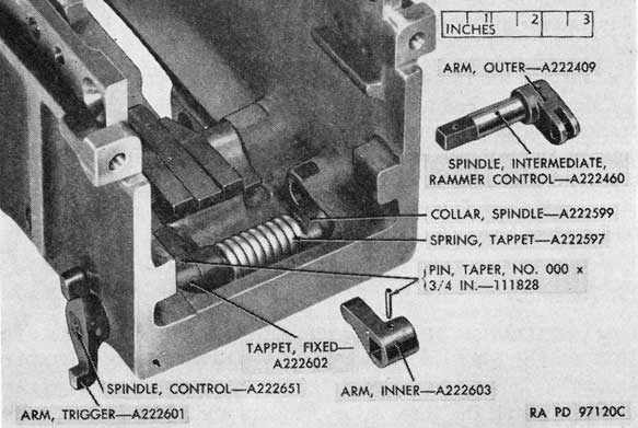
Figure 31. Phantom view of base group of automatic loader.
b. DISASSEMBLY OF LOADING TRAY.
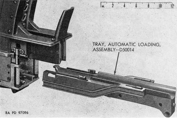
(1) Remove the automatic loader from the gun (TM 9-251 or TM 9-252); remove the tray by pulling it forward from the front end of the loader (fig. 32). Do not lose the rollers from the feed rods.
Figure 32. Loading tray removed from loader assembly.
80
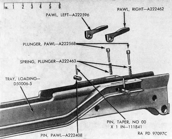
Figure 33. Parts of loading tray pawl mechanism.
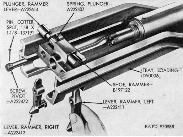
Figure 34. Parts of rammer shoe mechanism.
81
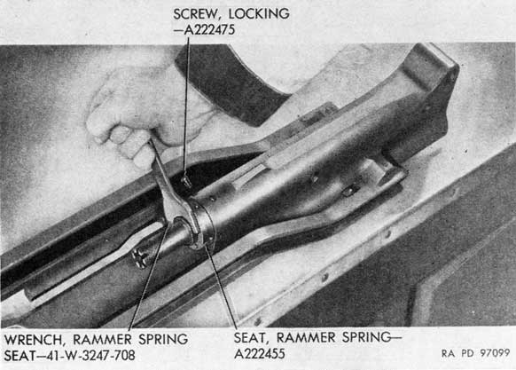
Figure 35. Removing rammer spring seat.
(2) Remove the taper pins and pawl pins and remove the loading tray pawls, plungers, and springs (fig. 33).
(3) Remove the cotter pin and nut from the rear end of the rammer rod. Slide the shoe assembly back to the larger portions of the slots in the tray. Remove the cotter pins from the lever pivot screws and remove the two pivot screws.
(4) Remove the two rammer levers through the openings at the sides of the tray (fig. 34). Slide the shoe out of the tray and remove the two plungers and the plunger spring from the shoe.
(5) Remove the locking screw at the under side of the loading tray and then unscrew the rammer spring seat, using the rammer spring seat wrench 41-W-3247-708 (figs. 11 and 35). Pull the rammer assembly from the tray.
(6) Remove the cotter pin and slotted nut that secure the rammer buffer pad assembly in the tray and push the pad assembly out through the rear opening (fig. 36).
(7) To disassemble the rammer assembly, drive out the taper pin that secures the rammer head to the rod, compress the rammer spring in an arbor press, and unscrew the rammer head from the rod, being careful to avoid sudden
82
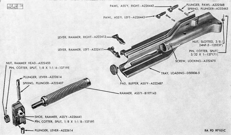
Figure 36. Parts of loading tray assembly.
83
Figure 37. Parts of rammer assembly.
release of tension of the springs; remove the rammer springs and spring seats (fig. 37).
c. REMOVAL OF CARTRIDGE GUIDES AND RAILS.
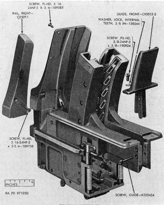
(1) Remove the front guide, after removing two screws and lock washers at the upper side and two guide screws at the ends of the frames (fig. 38).
(2) Remove the right rail, after removing two short screws at the rear of the rear guide and one long screw at the front of the rail (fig. 38). The left rail of the right loader for dual gun M2 is removed in the same manner.
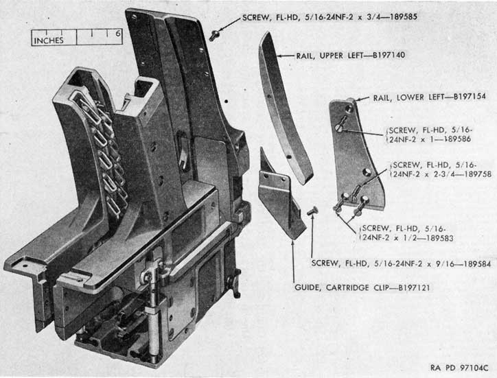
(3) Remove the lower left rail, after removing the four retaining screws (fig. 39). Remove two screws that secure upper left rail to the rear guide and remove this rail. The right rails for the right loader are removed in the same manner.
(4) Remove the two screws that retain the cartridge clip guide and remove the guide (fig. 39).
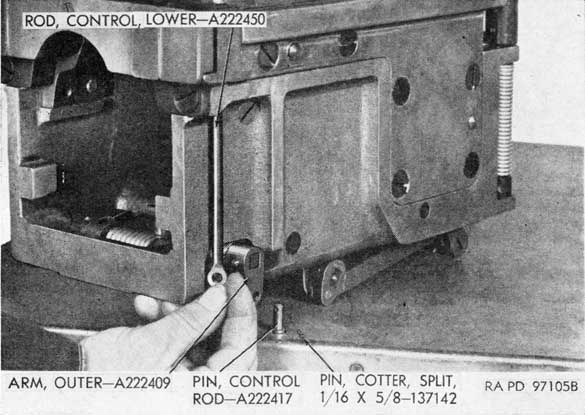
(5) Remove the cotter pin and control rod pin that attach the lower control rod to the outer arm of the intermediate rammer control spindle assembly. Unscrew the lower control rod from the upper control rod (fig. 40).
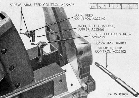
(6) Remove the small screws that secure the feed control arm and lever on the feed control spindle in the rear guide. Remove the spindle, the arm, and the lever from the guide (fig. 41).
(7) Remove the cotter pin, clevis pin, and upper control rod from the arm, if necessary.
(8) Remove four screws that retain the rear guide and remove the guide (fig. 41).
84
Figure 38. Front cartridge guide and right rail.
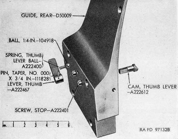
(9) To remove the thumb lever cam assembly from the rear guide, drive out the taper pin that secures the lever to the cam, remove the cam from the front of the guide, and remove the lever, ball, and spring from the rear (fig. 42). The stop screws for the lever may be removed from the guide, if necessary (fig. 42).
d. REMOVAL OF FEED ROLLER PLUNGERS.
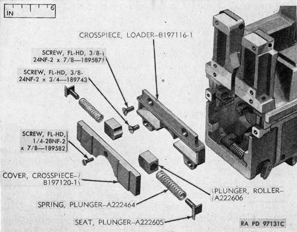
(1) Remove the crosspiece cover, after removing the retaining screw (fig. 43).
85
Figure 39. Upper and lower left rails and cartridge clip guide.
86
Figure 40. Removing lower control rod.
(2) Compress the feed roller plunger springs and remove the plungers, springs, and seats from the crosspiece (fig. 43).
Figure 41. Feed control arm, lever, and spindle.
87
Figure 42. Parts of thumb lever cam assembly.
Figure 43. Loader crosspiece and related parts.
88
Figure 44. Removing frame from base.
(3) Remove the automatic loader crosspiece, after removing the four retaining screws (fig. 43).
e. REMOVAL OF FRAMES AND FEED ROLLERS. (Both frames and feed rollers are removed in the same manner.)
(1) Drive out the two taper pins and remove the six screws that secure the frame to the base of the loader (fig. 44). When removing the pin near the rear of the frame, be careful not to damage the feed roller.
(2) Remove the frames, with feed roller assemblies and other parts, by lifting them straight up from the base to disengage the brackets from the feed roller catch head assemblies (fig. 45).
f. DISASSEMBLY OF THE FRAME GROUPS.
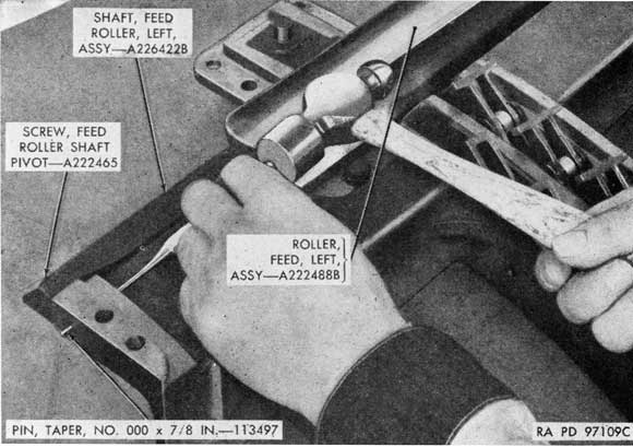
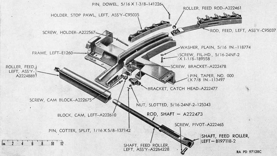
(1) Drive out the taper pin that secures the feed roller shaft pivot screw to the frame (fig. 46). Remove the pivot screw and remove the feed roller shaft and roller assemblies as a unit. Remove the roller from the shaft (fig. 47).
(2) Remove the feed rod assembly, after removing the holder screw that retains it in the frame (fig. 47).
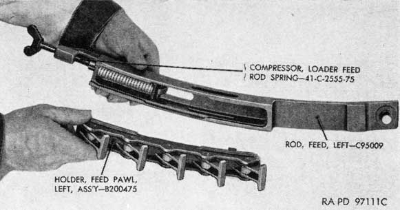
(3) To disassemble the feed rod assembly, compress the plunger spring, using the loader feed rod spring compressor - 41-C-2555-75, (figs. 8 and 48) and remove the feed pawl holder assembly (fig. 48). Remove the
89
Figure 45. Loader base and frame.
90
Figure 46. Removing feed roller and shaft assemblies.
compressor and remove the plunger spring and feed rod plunger (fig. 49).
(4) Remove the stop pawl holder assembly, after removing the three retaining screws, with washers, and dowel pin (fig. 47).
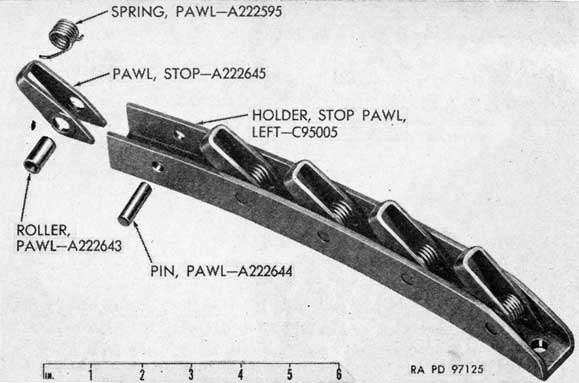
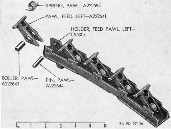
(5) To disassemble either the feed or stop pawl holder assembly, push out the pawl pins and remove the pawls, springs, and rollers from the holder (figs. 50 and 51).
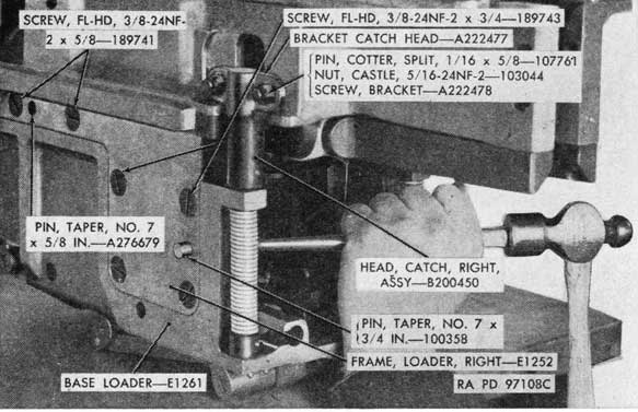
(6) Remove the two cotter pins, nuts, and screws which retain the catch head bracket and remove the bracket (fig. 47).
(7) Remove the catch head pawl cam block from the frame, after removing the two retaining screws (fig. 47).
g. REMOVAL AND DISASSEMBLY OF FEED ROLLER CATCH HEAD ASSEMBLIES.
(1) The right and left assemblies are removed and disassembled in the same manner. Be sure that parts of the left and right catch head assemblies are segregated. They are not interchangeable. They may be removed without removing the frames, if desired. In that event, the catch head bracket must be removed from the frame. Refer to f (6) above.
91
Figure 47. Components of left frame group.
92
Figure 48. Disassembling feed rod assembly.
(2) Drive out the taper pin that secures the spindle arm on the spindle and remove the spindle with attached catch head (fig. 52).
Figure 49. Components of feed rod assembly.
93
Figure 50. Parts of left stop pawl holder assembly.
(3) Unhook the catch head spring ends from the spindle arm and the loader base and remove the spring and the spindle arm (fig. 52).
Figure 51. Parts of left feed pawl holder assembly.
924807°-51-7
94
Figure 52. Removing catch head assemblies.
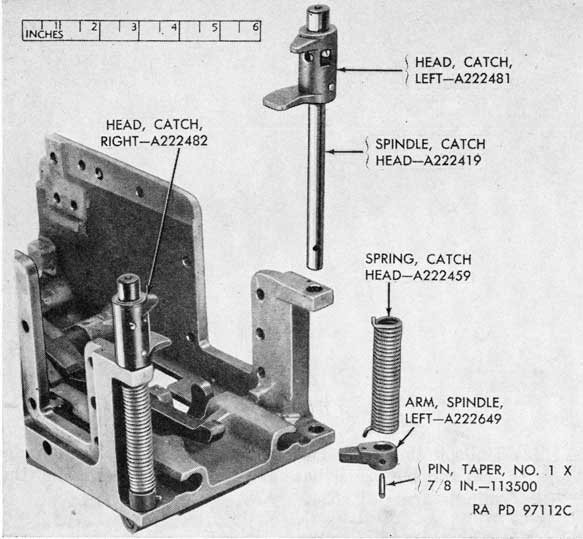
(4) Drive out the taper pin that secures the head on the spindle and remove the head. To remove the pawl from the head, remove the small screw from the pawl axis pin and remove the axis pin, pawl, spring, and plunger (fig. 53).
Figure 53. Parts of left catch head assembly.
95
(5) To disassemble the catch head assemblies with the frames in position, the heads, springs, and arms must first be removed; the spindles may then be removed from the under side of the base.
h. REMOVAL AND DISASSEMBLY OF CATCH RELEASE MECHANISM AND COCKING LEVERS.
(1) Working from the under side of the base, drive out the taper pins that secure the catch release arm and the two release spindle levers on the catch release spindle and remove the spindle or push it through to release the spindle arm (fig. 54).
(2) Remove the set screw from the shaft arm and drive out the taper pin that secures the right cocking lever to-the shaft (fig. 54). Move the shaft endwise to free the shaft arm (fig. 54).
(3) This releases the catch release link, with attached arms. Remove the cotter pin and link pin from the catch release arm and the shaft arm pin from the shaft arm and remove the arms from the link (fig. 54).
(4) Remove the catch release spindle levers from the catch release pistons and remove the pistons from the base (fig. 55).
Figure 54. Removal of catch release link and arms.
96
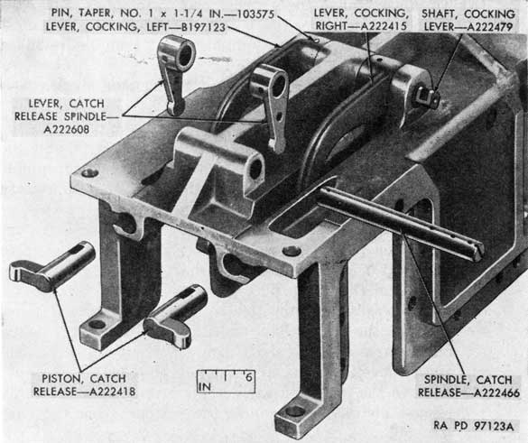
Figure 55. Removal of release spindle lever and release pistons.
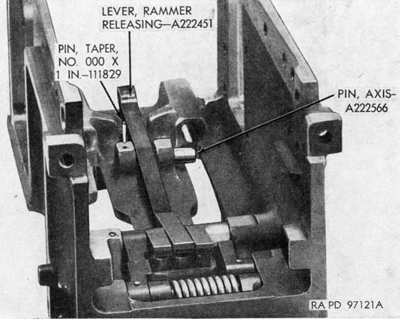
Figure 56. Removing rammer releasing lever.
97
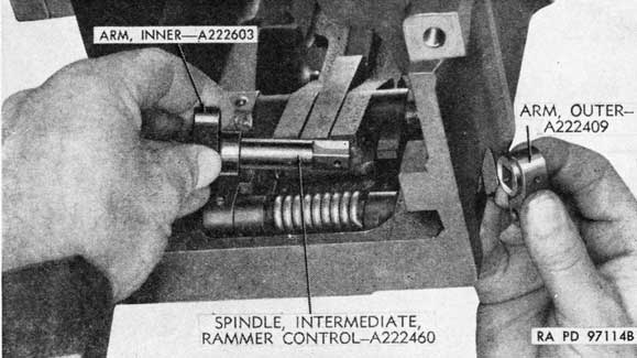
Figure 57. Removing intermediate rammer, control spindle assembly.
(5) Drive out the taper pin that retains the left cocking lever on the shaft and remove the shaft and the two levers (fig. 55).
(6) Drive out the taper pin that retains the axis pin in the base and remove the axis pin and the rammer releasing lever (fig. 56). (The taper pin is driven out from underside of base.)
i. REMOVAL OF RAMMER CONTROL SPINDLE ASSEMBLY, INTERMEDIATE SPINDLE ASSEMBLY, AND CATCH LEVER MECHANISM.
(1) Remove the taper pin that retains the outer arm on the spindle and remove the outer arm. Remove the spindle and inner arm from inside the base (fig. 57). Remove the taper pin from the inner arm and remove the arm.
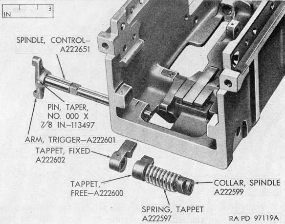
(2) Remove the taper pin from the fixed tappet (fig. 58). Then remove the spindle, with attached trigger arm, from the base. Remove the fixed tappet (fig. 58). Remove the collar, the free tappet, and the tappet spring (fig. 58). Remove the retaining taper pin and then remove the trigger arm from the spindle (fig. 58).
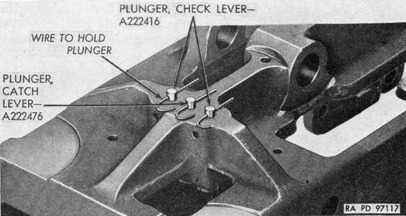
(3) With the base upside down, depress the three plungers and secure them in depressed position (fig. 59) and then drive out the taper pin that retains the lever axis pin in the base and remove the axis pin and the three levers (fig. 60). Also remove the three plungers and plunger springs.
98
Figure 58. Removing control spindle and tappets.
j. REMOVAL OF FEED ROLLER SUPPORTS. The feed roller supports may be removed from the base, if necessary, by removing the three retaining screws from each support (fig. 45).
Figure 59. Catch and check lever plungers in depressed position for
removing and installing catch and check levers.
99
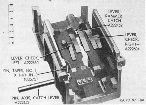
Figure 60. Catch and check levers.
Figure 61. Checking fit of feed roller and shaft.
100
34. Repair, Overhaul, and Rebuild
a. Clean the parts of the automatic loader assembly and inspect for wear or damage. Check parts (gun M1) for surface treatment (par. 27).
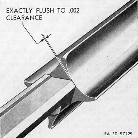
b. Look for breaks on the feed rollers and feed roller journals and see that moving parts are smooth and in good condition. Check the roller bushings for wear or damage. Remove minor abrasions from polished surfaces with crocus cloth. Assemble the roller and shaft and check for freedom of rotation. The shoulder of the shaft must not project beyond the curved surface of the roller at any point (fig. 61). The shaft surface may be up to 0.002 inch below the roller surface. The shoulder of the shaft may be filed and polished at this point, if necessary.
c. Inspect each spring for breaks, cracks, or distortion; if any of these conditions exist, replace the spring. The characteristics of the springs in the automatic loader should be approximately as follows:
Spring
Approximate free height
Solid height
Load or torque
Spring, cartridge rammer, inner-B260936.
17 in
4.75 in max.
30 to 36 lb at 12.20 in and 68 to 82 lb at 6.30 in.
Spring, cartridge rammer, outer-B260937.
17 in
4.85 in max.
70 to 84 lb at 12.20 in and 145 to 175 lb at 6.30 in.
Spring, catch head, left-A222459.
3 5/16 to 3 13/32
3.07 in max.
8.66 to 10.86 in-lb at 255° deflection.
Spring, catch head, right-A222594.
3 5/16 to 3 13/32
3.07 in max.
8.66 to 10.86 in-lb at 255° deflection.
Spring, catch head pawl plunger-A222647.
27/32 in
0.49 in max.
13.4 to 17.8 lb at 0.53 in.
Spring, catch lever plunger-A222456.
1 21/32 in
0.82 in max.
21.2 to 30.0 lb at 0.984 in.
Spring, check lever plunger-A222456.
1 21/32 in
0.82 in max.
21.2 to 30.0 lb at 0.984 in.
Spring, feed roller plunger-A222464.
3 in
1.26 in max.
28.7 to 39.9 lb at 1.34 in.
Spring, free tapp-A222597.
23.2 to 29.8 lb on 0.98 radius for 54° deflection.
Spring, loading tray pawl plunger-A222463.
1 7/32 in.
0.59 in max.
11.0 to 15.4 lb at 0.63 in.
Spring, pawl holder-A222595.
0.78 to 1.22 in-lb at 60° deflection.
Spring, rod plunger-A222646.
4 1/4 in.
3.18 in max
287 to 375 lb at 3.31 in.
Spring, shoe plunger-A222407.
2 13/16 in.
1.81 in max
47.4 to 60.6 lb at 1.85 in.
Spring, stop pawl-A222595.
0.78 to 1.22 in-lb at 60° deflection.
Spring, thumb lever ball-A222400.
7/16 in
3.3 to 5.5 lb at 0.265 in.
101
d. Examine the check levers and catch lever and their actuating plungers for distortion and wear. The surfaces of the levers must be smooth.
e. Inspect the rammer springs for breaks or cracks.
f. Inspect the pad assembly and the rammer shoe for burs and cracks. The pad assembly should prevent direct metal contact between the rammer head and the body of the loading tray when the rammer comes forward.
g. See if there is a 5/16 X 21/32-inch slot in the longer arm of the feed control lever (fig. 41) (MWO A50-W12).
35. Assembly
a. INSTALLATION OF THE CATCH LEVER MECHANISM, RAMMER CONTROL SPINDLE ASSEMBLY, AND INTERMEDIATE SPINDLE ASSEMBLY.
(1) Install the three lever plungers and plunger springs in the base. Secure the plungers in depressed position with cotter pins or wire (fig. 59). The plunger with the flanged head is assembled in the center opening.
(2) Place the left check lever, the catch lever, and the right check lever in position in the base and install the axis pin for these levers (fig. 60). Aline the hole in the axis pin with the hole in the base and install the taper pin (fig. 60).
(3) Install the trigger arm on the control spindle and install the taper pin (fig. 58).
(4) Assemble the free tappet and the spindle collar on the ends of the tappet spring (fig. 58). Hold these parts and the fixed tappet in position in the base while installing the spindle (fig. 58). The tappets must engage the left check lever. As the spindle is installed, turn the collar counterclockwise slightly to wind the spring, at the same time exerting pressure on the spindle to aline the collar with the square portion of the spindle, and install the taper pin in the fixed tappet.
(5) Install the outer arm on the intermediate rammer control spindle and install the taper pin (fig. 62). Hold the inner arm in position in the base, with the projection over the arm of the check lever, install the spindle in the case, and install the taper pin for the inner arm (fig. 62).
(6) Remove the retaining cotter pins or wires from the three lever plungers (fig. 59).
102
Figure 62. Installing control spindle assemblies.
b. INSTALLATION OF THE CATCH RELEASE MECHANISM AND COCKING LEVER SHAFT ASSEMBLY.
(1) Install the rammer releasing lever in position with the rear end under the catch lever (fig. 56). Install the lever axis pin and the taper pin for the axis pin (fig. 56).
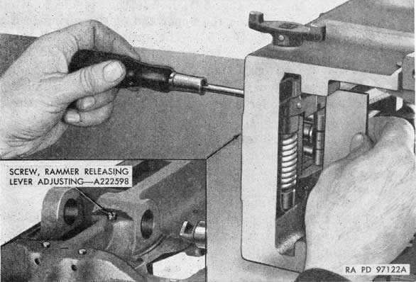
(2) The rammer releasing lever adjusting screw (fig. 63) is staked in position at original assembly and seldom requires adjustment. If a new releasing lever, catch lever, or screw is installed, adjust the screw to bring the catch lever flush with the two check levers, as determined with a short straightedge (fig. 63). Stake the screw after correct adjustment has been made.
(3) With the base upside down, start the cocking lever shaft through the center opening in the base. Hold the right cocking lever in position to aline the pin holes in the lever and the shaft and push the shaft through the openings in the base (fig. 55). Rotate the shaft and lever and install the left cocking lever on the shaft lever and the shaft (fig. 55). For the right loader of gun M2, install the right cocking lever first and then the left lever.
(4) Install the two catch release pistons in position in the case (fig. 55). Install the two catch release levers in position with the ends in the slots of the pistons (fig. 55). Hold the levers in position and install the spindle
103
Figure 63. Adjusting position of catch and check levers.
(fig. 55). Do not install the taper pins in the levers at this time.
(5) Install the arm of the catch release spindle assembly and the arm of the cocking lever shaft assembly on the catch release link, with the pin and cotter pin in the spindle arm and the pin in the shaft arm (fig. 54).
(6) Hold the catch release spindle arm and the cocking lever shaft arm, with the link in position to receive the spindle and shaft (fig. 54). Push the spindle and the shaft into position and install the taper pins for the spindle arm and the two catch release levers and locking screw for the shaft arm (fig. 54). Also install the taper pin in the right cocking lever (fig. 54).
c. ASSEMBLY AND INSTALLATION OF THE CATCH HEAD ASSEMBLIES.
(1) Both assemblies are installed in the same manner.
(2) Install the spring, plunger, and pawl in the head (fig. 53). Hold in position and install the pawl axis pin and the locking screw for the axis pin (fig. 53).
(3) Install the head on the spindle and install the taper pin (fig. 53).
(4) Engage one end of the catch head spring in the arm and place these parts in position in the base (fig. 52). Install the spindle with attached head through the openings in the base, spring, and arm and install the taper
104
pin for the arm (fig. 52). Rotate the spindle to wind the spring and hook the upper end of the spring in the hole in the base (fig. 52). The spring in the left catch head assembly is wound left and that for the right assembly is wound right.
d. INSTALLATION OF THE FEED ROLLER SUPPORTS. Install the right and left feed roller supports on the base with the three retaining screws (fig. 45).
e. ASSEMBLY AND INSTALLATION OF THE FRAMES.
(1) Install the catch head pawl cam block on each frame with the retaining screw (fig. 47).
(2) Install the catch head bracket on each frame with two screws, nuts, and cotter pins (fig. 47).
(3) Both the stop pawl and feed pawl holder assemblies are assembled in the same manner. Place each pawl spring in position in the pawl with the longer end pointed toward the lower end of the holder (figs. 50 and 51). Install the roller in the pawl, hold the pawl, spring, and roller in position in the holder, and install the pawl pin (figs. 50 and 51).
Caution: While the stop pawls are interchangeable, the right and left feed pawls are not. Install the feed pawls so that when the feed rod assemblies are in position in the frames, the beveled surfaces of all the feed pawls are toward the rear of the loader.
(4) Install the stop pawl holder in position in the frame and install the three screws with washers and the taper pin (fig. 47).
(5) Install the feed rod spring over the plunger and place these parts in the feed rod (fig. 48). Compress the spring completely, using the feed rod spring compressor - 41-C-2555-75 (fig. 48). Install the feed pawl holder assembly in the rod and remove the spring compressor. Install the assembly in the frame and install the long screw to hold it in place (fig. 47).
(6) Install the feed roller assemblies on the feed roller shafts (fig. 47) and check to see that the shaft shoulder is flush with the roller surface (par. 34 b). Install these parts in position in their respective frames. Install the shaft pivot screw at the end of each shaft and install the taper pin for each screw (fig. 46).
(7) Install the frames in their respective positions on the base and install the six screws and two taper pins for each frame (fig. 44). Tighten the screws securely and check to see that the screws and taper pins do not extend
105
beyond the inner surface of the base. Stake the screws in place.
(8) If a new frame or a new base is installed, the taper pin holes must be drilled and reamed at assembly. Install the frame with the retaining screws and complete the assembly of the loader. Check the operation to determine whether the frame and base are correctly alined. Position of the frame may be changed slightly by tapping it with a lead hammer after the screws have been loosened and shim stock may be inserted between the frame and the base to hold the alinement while the holes are drilled. Drill and ream the holes for the taper pins, remove the shim stock, if used, and drive the pins into position. Then tighten the retaining screws and stake them in place.
f. INSTALLATION OF THE FEED ROLLER PLUNGERS.
(1) Install the cross piece at the rear of the loader with the four retaining screws (fig. 43).
(2) Install the plunger, spring, and seat for each journal (fig. 43).
(3) Check the clearance between the cross piece and the plungers. Clearance at this point must be from 0.002 to 0.010 inch. Install the cross piece cover with retaining screw.
g. CHECKING CLEARANCE BETWEEN CATCH HEAD ARMS AND FEED ROLLERS.
(1) Measure the clearance between the upper arm of each catch head and the feed roller. Clearance should be from 0.008 to 0.020 inch.
(2) If clearance at this point is not within the specified limits, the arms of the catch heads may be filed a small amount to increase clearance. If clearance is too much, replace the defective catch heads. Clearance should be approximately equal for both rollers.
h. INSTALLATION OF THE FEED CONTROL ASSEMBLY, FRONT AND REAR GUIDES, CLIP GUIDE, AND RAILS.
(1) Install the spring and ball in the thumb lever, hold these parts in position at the rear of the guide, and install the cam from the front side (fig. 42). The cam must be in the same position with respect to the lever as shown in figure 42. Install the taper pin in the lever and cam (fig. 42). Install the two stop screws in the rear of the guide (fig. 42).
(2) Install the rear guide, with four screws (fig. 41).
106
(3) Attach the upper feed control rod to the control arm with the pin and cotter pin, hold the arm and the control lever in position in the rear guide, and install the spindle (fig. 41). Aline the screw holes in the spindle with those in the arm and lever and install the arm screws (fig. 41).
(4) Screw the lower feed control rod into the upper rod, then adjust the lower end, and attach it to the outer arm of the intermediate control spindle assembly with the pin and cotter pin (fig. 40). To adjust the lower feed control rod, first insert a 0.150-inch gage block or thickness gage under the right check lever and install two dummy cartridges in the loader to position the feed control lever. Next rotate the feed control thumb lever to the left for a left hand gun or to the right for a right hand gun and hold the intermediate spindle outer arm up in position. Then adjust the lower rod until up and down movement is eliminated and the clevis pin can be installed. Remove the dummy cartridges and the thickness gage. Rotate the thumb lever and observe the point at which spring tension is felt against the check lever. Tension should occur when the thumb lever has been rotated about 45 degrees.
(5) Install the cartridge clip guide with two guide screws (fig. 39).
(6) Install the upper left rail with two screws through the rear guide and install the lower left rail with four screws (fig. 39). The two longer screws go through the lower rail into the upper rail. On the right loader for the gun M2, these are the upper and lower right rails.
(7) Install the right rail with two screws from the rear and one from the front (fig. 38). On the right loader for the gun M2, this is the left rail.
(8) Install the front guide with two screws and lock washers at the top of the frame and two guide screws at the side (fig. 38).
i. ASSEMBLY OF LOADING TRAY.
(1) Install the seat, springs, and seat on the rod. Compress the springs in an arbor press and screw the head on the rod (fig. 37). Aline the pin holes in the head with the hole in the rod and install the taper pin (fig. 37).
(2) Install the pad assembly in the tray and install the nut and cotter pin (fig. 36).
(3) Install the rammer assembly in the tray and screw the rammer spring seat into position, using the rammer
107
spring seat spanner wrench - 41-W-3247-708 (figs. 11 and 35). Aline the holes for the locking screw and install the screw (fig. 35).
(4) Install the two rammer lever plungers and compression springs in the rammer shoe, hold the plungers in the shoe, and slide the shoe into the rear end of the tray (fig. 34). Install one rammer lever, up through the large opening in the tray, and install the pivot screw (fig. 34). Push the opposite plunger in against spring compression and install the other lever and pivot screw (fig. 34). After tightening the pivot screws, check to see that they do not protrude beyond the face of the shoe. If the screws protrude, replace them with shorter ones or file the ends. Aline the screws for cotter pins and install the pins (fig. 34).
(5) Slide the shoe assembly into position against the rammer spring seat and install the nut on the rammer rod. Draw the nut up very tight to hold the shoe firmly against the rammer spring seat. If the cotter pin opening in the nut is not alined with that in the rod, remove the nut and file the face of the nut enough to permit alinement of the openings with the nut fully tightened. Install the cotter pin.
(6) Install the spring and plunger for each loading tray pawl (fig. 33). Install each pawl and pawl pin (fig. 33). Drive in taper pin through each pawl pin (fig. 33).
(7) Install the rollers on the feed rod assemblies with the chamfered edge next to the tray and install the loading tray assembly in the loader (fig. 32). Be sure that the feed rod rollers enter the slots at the sides of the tray. Install loader in gun (TM 9-251 or TM 9-252).
j. CHECKING CLEARANCE BETWEEN CATCH (CENTER) LEVER AND THE RAMMER SHOE.
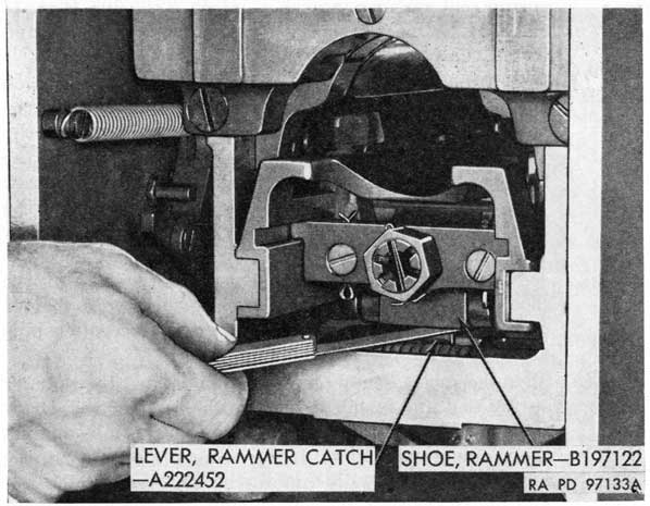
(1) To do this, open rear cover of breech casing (TM 9-251 or TM 9-252), cock the gun, and determine the clearance between the lever and the shoe, using a thickness gage (fig. 64). The proper clearance should be between 0.020 and 0.050 inch.
(2) If the clearance between the catch lever and the rammer shoe exceeds 0.050 inch, remove the rammer releasing lever (par. 33 h) and surface-grind the front pad on this lever to bring the clearance within the limits. If the clearance is found to be less than 0.020 inch, replace the releasing lever.
108
Figure 64. Checking clearance between the catch lever and the rammer shoe.
(3) Close the rear cover assembly, and install the top through bolt and nut (TM 9-251 or TM 9-252).
Section III. RECOIL CYLINDER ASSEMBLY
36. Trouble Shooting
a. GENERAL. Since the purpose of the recoil cylinder assembly and the recuperator spring is to control movement of the gun in recoil and counterrecoil, any condition that interferes with efficient operation of the mechanism may cause malfunction of the gun and result in serious damage to materiel or injury to personnel. Before attempting to correct a malfunction, ascertain that all other conditions affecting operation of the gun are favorable. For example, the recoil cylinder must be filled to correct level with the prescribed recoil fluid, the control rod valve spindle must be correctly adjusted, the gun must be properly lubricated, the recuperator spring must be in good condition, and the locking collar must be tightened properly (TM 9-251 or TM 9-252).
b. EXCESSIVE RECOIL OR VIOLENT RECOIL OR COUNTERRECOIL. Excessive or violent recoil is usually the result of a defective
109
recuperator spring or loose locking collar (par. 28). However, this condition, as well as violent counterrecoil, may be caused by leakage of oil in the recoil cylinder resulting from worn or damaged packing rings in the piston rod assembly or the control rod valve spindle. To correct, disassemble and replace defective packing rings (pars. 33 and 39).
c. GUN IS SLOW IN RECOIL AND COUNTERRECOIL OR RECOIL IS TOO SHORT. Trouble of this kind may be caused by too tight packing rings, a bent or damaged cylinder, corrosion of the rod surfaces, or improperly assembled recoil cylinder anchor bracket. Replace defective parts, as required (pars. 37 and 39).
37. Disassembly
a. Remove recoil cylinder from gun and drain it (TM 9-251 or TM 9-252).
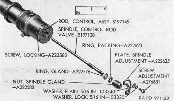
b. Remove the spindle adjustment plate after removing the adjustment screw and two washers (fig. 65). Loosen the locking screw from control rod assembly (fig. 65). Remove the spindle gland nut, the valve spindle, the packing ring, and the gland ring (fig. 65).
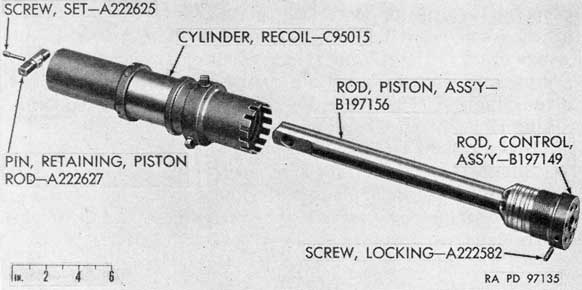
c. Remove the set screw from the piston rod retaining pin and remove the pin (fig. 66). Remove the locking screw and unscrew the control rod assembly from the cylinder, using the smaller end of the wrench - 41-W-3248-459 (fig. 11); remove the piston rod assembly and control rod assembly from the cylinder as a unit (fig. 66). Pull the control rod assembly away from the piston
Figure 65. Parts of valve spindle and adjustment plate mechanism.
924807°-51-8
110
Figure 66. Recoil cylinder and rod assemblies.
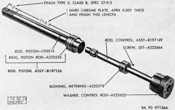
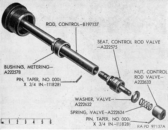
rod assembly far enough to gain access to the metering bushing, remove the set screw from the bushing, and unscrew the bushing from the piston rod (fig. 67), using the spanner wrench - 41-W3248-548 (fig. 11). Remove the control rod washer from control rod assembly (fig. 67). To disassemble the control rod assembly, drive out the two taper pins that secure the control rod valve nut and the control rod valve seat in the rod (fig. 68), then unscrew the seat from the rod, and remove the nut, spring, and washer
Figure 67. Control rod and piston rod assemblies.
111
Figure 68. Parts of recoil cylinder control rod assembly.
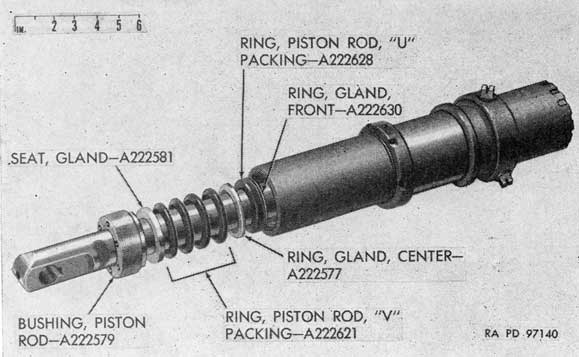
Figure 69. Parts of recoil cylinder piston rod bushing, packings, gland rings, and gland seat.
112
from the seat (fig. 68) and the metering bushing from the control rod (fig. 68).
d. Remove the piston rod bushing from the rear end of the cylinder (fig. 69), using the smaller end of wrench -41-W3248-459 (fig. 11). Remove the gland seat, four packing rings, the center gland ring, the U packing ring, and the front gland ring from the cylinder, if necessary (fig. 69).
e. The recoil cylinder collar (fig. 69) may be removed with spanner wrench - 41-W-3248-459, using the larger end (fig. 11).
38. Repair, Overhaul, and Rebuild
a. Clean the parts of the recoil cylinder assembly and inspect for wear or damage. Check parts (gun M1) for surface treatment (par. 27).
b. See that all polished surfaces are free from rust, scratches, and corrosion. Polish with crocus cloth to remove minor abrasions.
c. Examine the packings and see that oil passages are free from obstructions. Replace damaged packings.
d. A cylinder that is damaged by dents or cracks will be replaced (depot maintenance only).
e. Replace control rod valve spring if broken, cracked, or distorted. The characteristics of the spring should be approximately as follows:
(1) Approximate free length 1 inch.
(2) Solid height 0.25-inch.
(3) Load of 2.0 to 2.8 pounds at 0.413-inch.
39. Assembly
a. Place the metering bushing on the control rod (fig. 68). Install the valve washer, valve spring, and control rod valve nut on the control rod valve seat (fig. 68). Aline the holes in the nut with the holes in the seat and install the taper pin (fig. 68). Install the seat, with attached parts, in the end of the control rod, aline the holes in the seat and the rod, and install the taper pin (fig. 68). The two taper pins must not extend beyond the outside diameter of the rod or nut in which they are installed. File the ends of the pins, if necessary, and polish the rod to make the surface smooth at these points.
b. Install the control rod assembly part way into the piston rod (fig. 67) and screw the metering bushing into position in the piston rod (fig. 67), using the spanner wrench - 41-W-3248-548 (fig. 11). Install the set screw in the bushing (fig. 67). Install the control rod washer in position on control rod (fig. 67). Install the piston rod, with the control rod assembly, in the cylinder
113
Figure 70. Installing recoil cylinder control rod assembly.
(fig. 66) and screw the control rod into the cylinder, using the smaller end of the wrench - 41-W-3248459 (figs. 11 and 70). Aline the control rod for installing the locking screw (fig. 70) but do not install the screw until the control rod valve spindle has been installed.
c. Assemble the front gland ring, the U packing ring, center gland ring, four V packing rings, and seat over the end of the piston rod and into the cylinder (fig. 69). Install the piston rod bushing in the rear end of the cylinder (fig. 69), using the smaller end of wrench - 41-W-3248-459 (fig. 11). Install the recoil cylinder collar on the cylinder, if removed (fig. 69). Install the piston rod retaining pin and set screw at the rear end of the piston rod (fig. 66).
d. Install the control rod valve spindle in the control rod and install the gland ring and packing ring over the spindle and screw the spindle nut into control rod (fig. 65). Turn the control rod valve spindle clockwise as far as it will go and then unscrew it one-third of a turn. Install the adjustment plate with two washers (fig. 65). Install the control rod locking screw (fig. 65).
114
Figure 71. Installing piston rod bushing, packings, gland rings,
and gland seat.
e. Install the recoil cylinder on the gun and fill with proper recoil fluid (TM 9-251 or TM 9-252).
Section IV. BREECH RING ASSEMBLY
40. Trouble Shooting
Malfunctions of the breech ring assembly are covered in detail in TM 9-251 or TM 9-252. Generally, these can be eliminated by removing burs and rough spots from contacting surfaces and replacing worn or broken parts (pars. 41, 42, and 43).
41. Disassembly
a. Remove and disassemble the breechblock assembly (fig. 72) (TM 9-251 or TM 9-252).
b. Remove and disassemble the breech ring assembly as instructed in TM 9-251 or TM 9-252 but with the safety plunger parts intact. To remove the safety plunger parts, remove staking indentations and unscrew the seat carefully by means of the seat wrench - 41-W-3734-100 (fig. 11). Make short counterclockwise and clockwise twists to prevent damage to the seat and wrench. Remove seat, plunger spring, and plunger (fig. 73).
115
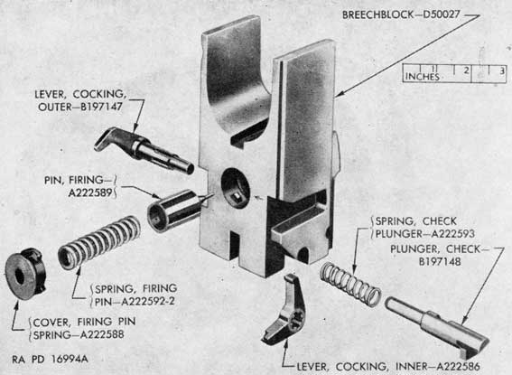
Figure 72. Parts of breechblock assembly.
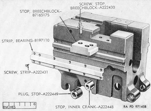
c. The breechblock stops bearing strips, and inner crank stop can be removed, if necessary, as follows:
(1) Breechblock stops (fig. 74) (depot maintenance only). Remove the two breechblock stop screws for each stop by means of a screw extractor. The stops (fig. 74) are pressed into position at assembly and their removal may be accomplished by pressing or driving them from the breech ring. Be careful not to damage the surface of the breech ring.
(2) Inner crank stops (fig. 74). To remove either stop, first remove the socket head stop plug at the side of the breech ring and then remove the stop. In breech rings of alternate design, the stop plugs are not of the socket head type and must be removed by means of a screw extractor.
(3) Bearing strips (fig. 74) (depot maintenance only). Remove the strip screws. The heads of these screws are ground flush with the bearing strip surfaces at assembly and may be removed with a screw extractor. Remove the bearing strips (fig. 74) and clean the surfaces of the ring in preparation for installing new strips.
a. Inspect each spring for breaks, cracks, and distortion; if any of these conditions are present, replace the spring. The characteristics of the springs should be approximately as follows:
Spring
Approximate free height
Solid height
Load
Spring, check plunger -A222593.
1 7/8 in.
8.8 to 11.0 lb at 0.709 in.
Spring, closing-B197113.
159 to 203 lb at radius of 3 5/8 for 145.50-deg twist.
Spring, firing pin-A222592.
2.350 in min
1.500 in. max.
110.2 to 127.8 lb at 1.65 in.
Spring, loading tray bolt-A222432.
1 1/8 in.
0.6 in. max
33 to 37 lb at 0.63 in.
Spring, safety plunger-A222445.
2 11/16 in.
0.8 in. max
9.0 to 10.0 lb at 1.06 in.
b. Inspect all contact surfaces of breechblock, extractors, and breech ring inner crank for upsetting and wear. Replace, if there is upsetting or if wear is sufficient to cause looseness of parts or improper functioning.
119
c. Check firing pin hole for wear (new type breechblock); replace breechblock if firing pin hole is large enough to cause blown primers. Check breechblock firing pin in bushing for wear: bushing should be tight and flush with face of breechblock (old type breechblocks only). If bushing is loose or worn, replace as follows:
(1) Tap against smooth end of bushing locking pin to loosen it.
(2) With the bushing wrench - 41-W-643-750 (fig. 10), unscrew the bushing.
(3) Position the locking pin so that its cut-out section is toward the bushing and screw in a new bushing tight.
(4) Tap locking pin, in from slotted end, tightly against bushing threads.
(5) Finish bushing flush with front face of breechblock.
d. Check firing pin for excessive wear, signs of fracture, and distortion; replace, if these defects are present. Check protrusion of firing pin; replace if it does not fall within the limits of 0.099 to 0.114 inch, measured with firing pin protrusion gage - 41-G182-300 (fig. 8).
e. Check condition of check plunger and replace if worn, cracked, or distorted. See if plunger has been modified to prevent fracture in accordance with drawing B197148, revision 3.
f. Inspect crankshaft assembly for condition of splines and distortion. Remove burs and rough spots from splines; if splines are distorted, replace crankshaft. Check outer crank roller for rotation and wear. Remove rough spots; if loose because of wear, replace.
g. Remove minor burs, abrasions, or corrosion from the breech ring threads or other surfaces by filing and polishing with crocus cloth.
h. Check parts (gun M1) for surface treatment (par. 27).
43. Assembly
a. The inner crank stops, bearing strips, and breechblock stops are assembled as follows:
(1) Breechblock stops (fig. 74).
(a) Press the stops into the breech ring, alining the stop screw openings (fig. 74).
(b) Install the two stop screws for each stop and tighten them evenly and securely.
(c) Cut off the driving lug portion of the screws and machine or file the screws flush with the surfaces of the stops.
120
(2) Inner crank stops (fig. 74). Insert each stop in position in the breech ring and install the stop plug. The longer plug is installed in the left side of the breech ring for the gun M1 or left breech ring of the dual gun M2 and in the right side of the right breech ring for dual gun M2.
(a) Mount the strips in position on the breech ring, with the screw holes alined with corresponding holes in the breech ring (fig. 74). Install the strip screws (4 for the short strip, 6 for the long strip on one side, and 12 for the single strip on the other side). Tighten the screws evenly and securely. New bearing strips are provided with approximately 1/32-inch of excess metal on all external surfaces; machine to following tolerances: distance between upper and lower side of each strip should be 0.699 to 0.703 inch and distance between extreme sides of the strips should be 8.242 to 8.248 inches. Slide the breech ring into the breech casing and move it back and forth to test for binding or roughness. The ring must move freely in the guides.
b. To assemble the safety plunger parts (fig. 73), replace the safety plunger and plunger spring, screw in the plunger spring seat by means of the seat wrench - 41-W-3734-100 (fig. 11). Stake the seat.
c. Assemble the breech ring assembly (fig. 73) (TM 9-251 or TM 9-252). Feel spring force against loading tray bolt spring sleeve; if insufficient to keep sleeve in its seat, replace loading tray bolt spring. Install breech ring (TM 9-251 or TM 9-252).
d. Assemble and install the breechblock assembly (fig. 72) (TM 9-251 or TM 9-252). Open breech and remove barrel assembly (TM 9-251 or TM 9-252); the safety plunger should prevent breech from closing when the firing pedal is depressed. If it does not, replace plunger spring, and recheck.
Section V. BREECH OPERATING MECHANISM
44. Trouble Shooting
a. BREECH OPERATING MECHANISM FAILS TO OPEN BREECH. Failure of the breechblock to open when the handle is operated may be caused by a defective lever rod, loose retaining nuts and bolts in the shaft assembly bracket, or poor contact of the rod with the outer crank of the breech ring assembly resulting from the lack of proper cleaning and lubrication. To correct this condition
121
remove and disassemble the mechanism, clean all parts thoroughly, and replace defective parts (pars. 45, 46, and 47).
b. BREECH OPERATING MECHANISM FAILS TO OPERATE THE COCKING LEVER. Failure of the mechanism to operate the cocking lever shaft assembly in the automatic loader. may be caused by a worn, distorted, or broken operating lever shaft or shaft arm. Replace defective parts (pars. 45, 46, and 47). Be sure that the screws on shaft bracket in breech casing are tight.
45. Disassembly
a. Remove automatic loader and breech ring assemblies (TM 9-251 or TM 9-252).
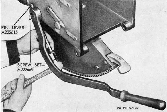
b. Remove the set screw and lever pin at the outer end of the hand operating lever shaft (fig. 75). Dismount the lever.
c. Remove the two safety nuts and bolts that secure the shaft bracket to the bottom of the breech casing (fig. 76).
d. Remove the cotter pin, slotted nut, and washer from the operating lever rod crank (fig. 76).
e. Drive the shaft and the crank into the breech casing and remove as a unit (fig. 77).
f. To disassemble, remove the two cotter pins and lever pins that attach the rod to the lever rod crank and to the operating lever shaft, remove the rod, drive out the taper pin that secures the shaft arm on the shaft, and remove the arm and bracket from the shaft (fir. 77).
Figure 75. Removing hand operating lever.
122
Figure 76. Removing hand operating lever crank and shaft assemblies.
g. To disassemble the lever latch front bracket assembly (fig. 76), remove the two retaining screws, remove bracket, plunger, and spring, and unscrew spring seat. The rear bracket assembly is disassembled similarly.
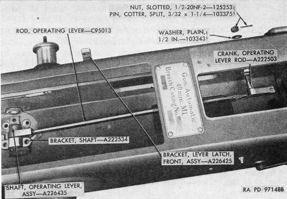
Figure 77. Parts of breech operating mechanism.
123
46. Repair, Overhaul, and Rebuild
a. Clean the parts of the hand operating mechanism and inspect for wear or damage. Check parts (gun All) for surface treatment (par. 27).
b. Examine the operating lever shaft for distortion and wear. If the portion of the shaft to which the arm is attached becomes twisted, the arm will fail to make proper contact with the automatic loader cocking lever and shaft should be replaced.
c. Check the rod for distortion.
d. See that all moving parts are free from corrosion and abrasion. Polish the parts to remove roughness. Replace distorted rod.
47. Assembly
a. If lever latch bracket assemblies were removed, screw in spring seat, install spring, plunger, and bracket, and secure with retaining screws.
b. Install the shaft bracket and arm on the shaft, aline the taper pin holes in shaft and arm, and drive in the taper pin. (fig. 77).
c. Attach the rear end of the operating lever rod to the shaft with the lever pin and cotter pin (fig. 77).
d. Install the lever rod crank on the operating lever rod with the lever pin and cotter pin (fig. 77).
e. Install the assembled parts in position in the breech casing (fig. 76); secure the shaft bracket to the bottom of the casing with the two bolts and safety nuts and secure the operating lever rod crank to side of casing with washer, nut, and cotter pin (fig. 77).
f. Install the operating lever on the shaft and install the lever pin (fig. 75). Aline the pin for the set screw and install the set screw in the end of the shaft (fig. 75).
g. Install breech ring and automatic loader (TM 9-251 or TM 9-252).
h. Pull the operating handle to the rear. Check to see that the operating mechanism actuates the cocking levers properly.
Section VI. BREECH CASING FIRING LINKAGE
48. General
a. The breech casing firing linkage of the gun M1 (fig. 78) is secured to the left side and bottom of the breech casing.
124
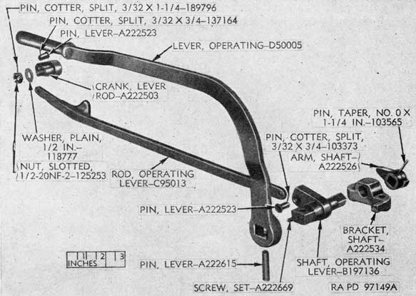
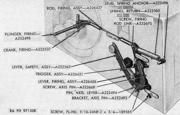
Figure 78. Phantom view of breech casing firing linkage.
b. The gun M2 has two symmetrically opposite breech casing firing linkages. The linkage in the left casing is identical with that of the gun M1. Most of the parts of the linkage in the right casing are not interchangeable with those in the left casing or in gun M1. Maintenance operations are the same for both.
49. Trouble Shooting
a. GUN CANNOT BE OPERATED ON SINGLE FIRE. Failure of the gun to single fire may be caused by a damaged firing lever pawl or pawl plunger spring in the firing lever assembly. To correct, remove and disassemble the firing lever assembly (par. 50). Remove minor abrasions or corrosion from the pawl. Replace a weak or broken pawl plunger spring or a badly damaged pawl (pars. 50 and 52). Adjust clearance between firing lever pawl and trigger (par. 53).
b. GUN MISFIRES. Misfire of the gun may be caused by incorrect adjustment of the firing rod assembly, loose or defective trigger or trigger spring, sheared taper pin in the trigger, or weak or broken lever return spring. To correct, adjust firing rod assembly (par. 53) and replace defective parts (pars. 50 and 52).
50. Disassembly
a. Remove the automatic loader assembly (TM 9-251 or TM 9-252).
125
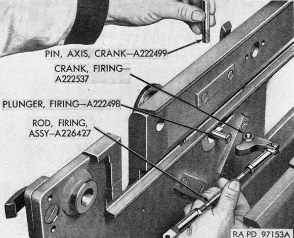
Figure 79. Removing firing crank with firing rod assembly.
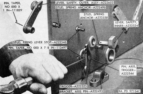
Figure 80. Removing safety levers and trigger.
924807°-51-9
126
Figure 81. Parts of breech casing firing linkage.
b. Unhook the return spring from the stud on the breech casing (fig. 78).
c. Remove the screw that attaches the rear link of the firing rod assembly to the firing lever assembly (fig. 78).
d. Remove the axis pin screw that holds the lever axis pin in the axis pin bracket, remove the axis pin, and remove the firing lever assembly (fig. 78).
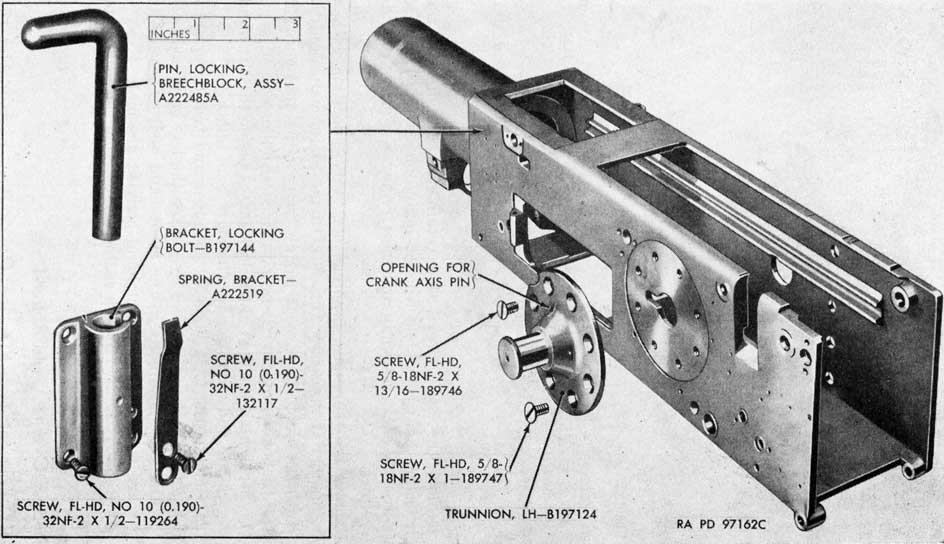
e. Remove the crank axis pin and then remove the firing crank with the firing rod assembly as a unit (fig. 79). Remove firing plunger from the trunnion (fig. 78).
f. Unhook the trigger spring from the trigger and from the
127
Figure 82. Parts of firing lever assembly.
stud in the breech casing, drive out the taper pin from the trigger, and remove the trigger and trigger axis pin (fig. 80).
g. Drive out taper pin that attaches outer safety lever to inner lever and remove both levers (fig. 80).
h. Remove cotter pin and crank pin and detach firing crank from the firing rod assembly (fig. 81). To disassemble the rod assembly, unscrew the two links and two rod nuts from the rod (fig. 83).
i. To disassemble the firing lever assembly, remove link screw and return spring and remove cotter pin, pawl axis pin, pawl, plunger, and spring (fig. 82), taking care not to lose the plunger spring.
j. The two spring anchor studs (field maintenance) that hold the trigger spring and return spring, the firing lever stop stud, and the axis pin bracket (depot maintenance) may be removed from the breech casing, if necessary (fig. 80).
51. Repair, Overhaul, and Rebuild
a. Clean all parts of the breech casing firing linkage and examine for wear or damage. Check parts (gun M1) for surface treatment (par. 27).
128
b. Check all springs for kinks, breaks, or cracks. If any of these conditions exist, replace the springs. The characteristics of the springs should be approximately as follows:
Spring
Approximate free height
Solid height
Load
Spring, firing lever-A222502.
2 17/32 to 2 29/32 in.
20 to 24 lb at 5 13/16 in.
Spring, lever plunger-A222506.
43/64 in
0.54 in. max
4.4 to 6.6 lb at 0.335 in.
Spring, pawl plunger-A222512.
1 3/8 in
0.54 in. max
4.41 to 6.61 lb at 0.65 in.
Spring, trigger-A222557.
1 9/64 in.
4.0 to 6.2 lb at 2.32 in.
c. Remove any rust or corrosion from operating surfaces. Smooth minor abrasions. In dressing surfaces, do not remove any more metal than is absolutely necessary. Avoid changing the contour of the operating surfaces as these are critical.
d. Replace parts that are distorted in any way.
52. Assembly
a. If the axis pin bracket (fig. 80) was removed from the breech casing, install the bracket with the two screws.
b. Install the two spring anchor studs and the firing lever stop stud in the breech casing (fig. 78).
c. To assemble the firing lever assembly, install the pawl plunger spring and plunger in the opening in the lever, install the pawl, and hold it against spring tension, while installing the pawl axis pin and cotter pin (fig. 82). Attach the return spring to the firing lever with link screw (fig. 82).
d. Assemble the firing rod assembly by installing the two nuts and two links on the rod (fig. 81). Install the firing crank on the front link of the firing rod with the pin and cotter pin (fig. 81).
e. Install the trigger axis pin in the breech casing (fig. 81). Hook the trigger spring on the trigger and install the trigger on the axis pin with the taper pin (fig. 81). Hook the other end of the trigger spring on its anchor stud.
f. Install the outer safety lever in the breech casing, install the inner safety lever on the outer lever from inside the breech casing, and secure with the taper pin (fig. 81).
g. Install firing plunger in trunnion (fig. 79). Install the firing crank with attached firing rod assembly in the breech casing and install the crank axis pin (fig. 79).
129
h. Place the firing lever assembly in position in the casing, install the lever axis pin, with the screw hole in the pin alined with the hole in the pin bracket, and install the axis pin screw in the bracket (fig. 78).
i. Attach the rear end of firing rod assembly to the firing lever with the firing rod link screw (fig. 78).
j. Hook the rear end of the return spring on its anchor stud (fig. 78).
53. Checks and Adjustment of Breech Casing Firing Linkage
a. Before making any adjustment to the firing linkage in the breech casing, make sure there is proper clearance between the firing plunger in the trunnion and the firing lever on the top carriage (par. 89 a). Install automatic loader in the breech casing and check adjustments of firing linkage.
b. If the gun fails to single fire, an adjustment may be made inside the breech casing. The automatic loader assembly must be removed to gain access to the firing rod.
c. Detach the front firing rod link from the firing crank (fig. 83).
d. Loosen the lock nut on the rod and turn the link clockwise to decrease the clearance between the firing lever pawl and the
Figure 83. Adjusting breech casing firing rod link.
130
trigger and counterclockwise to increase the clearance (fig. 83). In the unfired position, there should be 1/32-inch clearance between the pawl and the trigger and the firing lever should rest against the stop. In the fired position (single fire) the firing lever must bottom against the trigger body. Free motion in firing lever pawl should not be less than 0.002 inch.
e. After making the adjustment, tighten the lock nut and attach the link to the firing crank.
f. Install the automatic loader assembly (TM 9-251 or TM 9-252).
Section VII. BREECH CASING
54. Trouble Shooting
a. GUN SLOW IN RECOIL AND COUNTERRECOIL. Damaged guideways in the breech casing body will cause the gun to be slow in recoil and counterrecoil and recoil action may be too short to operate the automatic loader properly. Mutilation of the guideways may be caused by accident, careless operation, or lack of proper cleaning and lubrication. The cause will be determined and corrected. Minor mutilations may be removed, but a badly damaged casing body will be replaced.
b. GUN HARD TO ELEVATE. A damaged or incorrectly installed elevating gear sector will cause difficulty in elevating and depressing the gun. Minor burs or roughness on the teeth of the sector may be removed, but a badly damaged sector will be replaced (pars. 57 and 59). If binding occurs between the elevating sector and elevating pinion, remove the sector and shim from the breech casing and install shims of correct thickness to raise the sector (par. 59 i). Binding at only one side of the sector may be corrected by installing shims of correct thickness between the trunnion bearing and the top carriage (par. 100 k or 218 f). Refer to chapter 6, sections II and VI; and chapter 7, sections V and VII for other causes of this malfunction.
55. Removal
Note. Many of the breech casing parts or smaller subassemblies including the top cover, side cover, bottom cover, rear cover, breech ring lock pin, breech ring stop, and operating handle brackets may be removed and disassembled individually at any time without disturbing any other major assemblies. Removal of the breech casing from the top carriage is seldom necessary, as most maintenance operations can be performed with the breech casing mounted on the carriage. Exceptions to this rule are replacement of the elevating gear sector, the casing body, the trunnions, and the equilibrator rod bracket (dual gun M2).
131
a. Remove the sighting equipment (refer to TM 9-1609, when published).
b. Remove recoil cylinder assemblies (TM 9-251 or TM 9-252).
c. Detach the equilibrators (pars. 63 and 171).
d. Using the leverage afforded by the barrel assembly and with the muzzle end supported by a block and tackle in order to avoid damaging the elevating mechanism by overloading of the gears, depress the gun. Engage the elevating hand crank and secure it to the carriage or platform to keep the gun in horizontal position.
e. Remove the barrel assembly (TM 9-251 or TM 9-252).
Note. If necessary, the breech casing with all parts assembled can be removed as instructed in j, k, l, and m below without removing the automatic loader, breech ring, breech operating mechanism, or breech casing firing linkage.
f. Remove automatic loader (TM 9-251 or TM 9-252).
g. Remove breech ring (TM 9-251 or TM 9-252).
h. Remove breech operating mechanism (par. 45).
i. Remove breech casing firing linkage (par. 50).
j. Remove the cotter pins and nuts from the two trunnion bearing studs and remove the trunnion bearing caps (fig. 146).
k. Arrange a rope or wire sling at the front and rear ends of the breech casing and attach the sling to the hook of a crane or hoist. The sling should hold the casing level when it is raised. If a wire sling is used, wrap the sling or insert wood blocks at points of contact to prevent damage to the casing.
l. Untie the elevation hand crank and remove it.
m. Raise the breech casing with the hoist, being careful not to damage the trunnion bearings. Place the casing on a suitable stand or on wood blocks, built high enough to prevent the elevating gear sector from being damaged.
56. Installation
Note. If the breech casing and all assembled parts were removed as a unit (see Note following par. 55 e), remove cotter pin, washer, and clevis pin from firing mechanism lever at left trunnion of gun M1 and both trunnions of gun M2, and drop lever away from plunger (figs. 128, 129, and 259). This should be done to avoid damaging the firing plunger when installing the breech casing.
a. Place a rope or wire sling on the breech casing assembly and attach the sling to the hook of a hoist. Install the breech casing in position in the top carriage. Lower the casing carefully into the trunnion bearings.
b. Install the trunnion bearing caps and secure with the nuts and cotter pins (fig. 146).
c. Engage elevation hand crank and secure it to the carriage or platform to keep gun in horizontal position.
132
Figure 84. Part of breech casing-rear end.
133
d. Install breech casing firing linkage (par. 52).
e. Install breech operating mechanism (par. 47).
f. Install breech ring assembly (TM 9-251 or TM 9-252).
g. Install automatic loader assembly (TM 9-251 or TM 9-252).
h. Install barrel assembly (TM 9-251 or TM 9-252).
i. Support the muzzle end of the barrel assembly with a block and tackle, untie the hand crank, and elevate gun about 90 degrees; engage hand crank and secure it to carriage or platform to prevent gun from dropping.
j. Attach the equilibrators (pars. 64 or 172).
k. Install the recoil cylinder assembly (TM 9-251 or TM 9-252). 1. Install the sighting equipment (refer to TM 9-1609, when published).
Note. Install the cotter pin, washer, and clevis pin and rod end pin, if these were removed from firing mechanism lever (figs. 128, 129, and 259).
57. Disassembly
a. Remove and disassemble the rear cover (fig. 84).
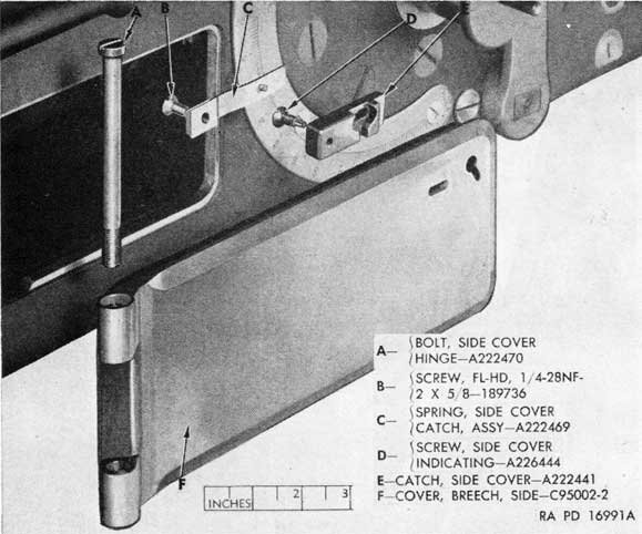
b. Remove and disassemble top, bottom, and side cover assemblies (figs. 85 and 86).
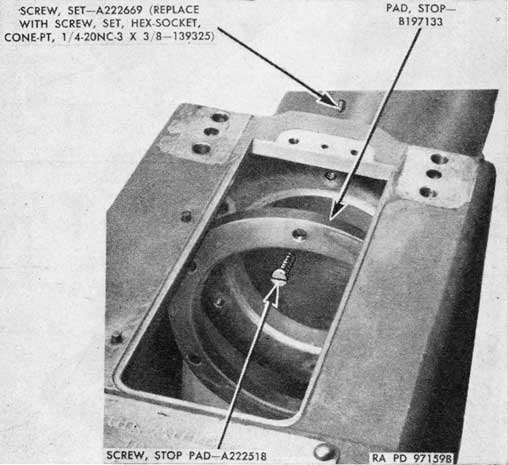
c. Remove the six set screws - A222669 that lock the stop pad screws (fig. 87). These set screws are located outside the breech casing (fig. 84); they are to be replaced with set screws - 139325.
d. Remove the stop pad through the top opening of the breech casing (fig. 87).
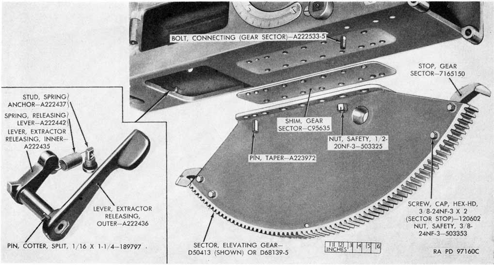
e. Remove the 14 safety nuts and bolts that secure the elevating gear sector to the breech casing (fig. 88) (depot maintenance only). Support the sector to prevent it from dropping.
f. Remove the two taper pins by driving them out from inside the casing (fig. 88) (depot maintenance only).
g. Remove the elevating gear sector and gear sector shim (figs. 88 and 89) (depot maintenance only). The elevating gear sector is removed in the same manner on guns M1 and M2.
h. The gear sector stops may be removed from the gear sector by removing the two safety nuts and screws for each stop (depot maintenance only).
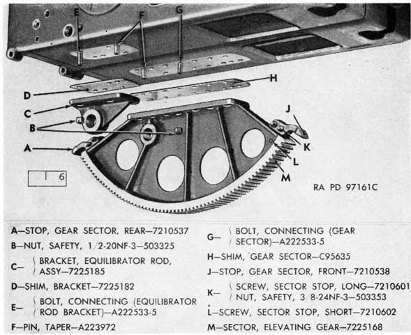
i. To remove the equilibrator rod bracket (depot maintenance only) from the gun M2, remove the four safety nuts, connecting bolts, and two taper pins. Dismount the bracket and bracket shim (fig. 89).
j. Remove the crank axis pin (fig. 79) (left trunnion on gun M1, either trunnion on gun M2).
134
Figure 85. Parts of top and bottom cover assemblies.
Figure 89. Elevating gear sector and equilibrator rod bracket (Gun M2).
k. Remove the eight screws that retain each trunnion on the breech casing body (fig. 90) (depot maintenance only). These screws are staked at assembly and their removal requires considerable effort.
l. Remove the trunnions, tapping them out of position with a copper hammer if necessary (fig. 90) (depot maintenance only).
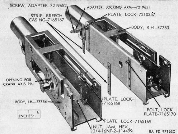
m. To disassemble the breech casing body of the dual gun M2 (fig. 91) (depot maintenance only) proceed as follows:
(1) Straighten the lugs of the lock plates inside the left hand casing body and remove the eight jam nuts.
(2) Remove the lock plates (two upper and two lower).
(3) Separate the two bodies by pulling the left hand body off the lock plate bolts in the right hand body. These bolts are welded to the right hand body at assembly.
(4) Remove the two breech casing strips from the lock plate bolts.
58. Repair, Overhaul, and Rebuild
a. Examine the breech casing for damage, particularly, the guideways. Minor mutilations of the guideway can be removed,
138
Figure 90. Left trunnion and breech casing (Gun M1).
139
Figure 91. Breech casing bodies of Gun M2.
but if casing body is badly damaged, it should be replaced (depot maintenance only).
b. Examine the elevating gear sector for abrasions and chips of teeth. Minor abrasions can be removed, but if sector is badly damaged, it should be replaced (depot maintenance only).
c. Replace the breech ring stop pad, if worn, distorted, or cracked.
d. Remove rough spots from trunnions. If trunnions are distorted in any way, they should be replaced (depot maintenance only).
e. Replace the springs, if broken or cracked. Characteristics of springs should be approximately as follows:
Spring
Approximate free height
Solid height
Load
Spring, release lever-A222442.
1 5/16 to 1 7/16 in.
5.5 to 7.7 lb at 4.13 in.
Spring, cover catch-A222637.
1 7/64 in
7.15 to 7.81 lb at 0.905 in; 18.41 to 20.17 lb at 0.630 in.
Spring, recoil indicator friction washer-A222617.
9/16 in
0.4 in max.
62 to 84 lb at 0.413 in.
140
f. Check all bushings in casing body for looseness. If any bushing is loose or if clearance between bushing and respective shafting is greater than 0.001 inch, drive out the bushing, install a new one, and ream to size (depot maintenance only).
g. Examine side covers for condition. Replace cover catch spring assembly if cover fails to latch or if spring pin is sheared off or damaged.
h. Check functioning of top cover catch spring; if it is broken or if it fails to operate cover latch, replace. See that top cover is properly stenciled with the words "CAUTION: LOCK COVER BEFORE FIRING" (MWO A50-W3).
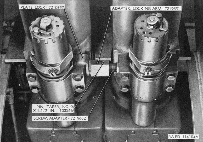
i. Examine lock plate, adapter screw, and locking arm adapter for condition (fig. 92). Repair any cracks in the weldments. If adapter screw is loose, replace the taper pin; if necessary, drill and ream a larger hole for a larger taper pin. Adapter should be installed with the converging sides forward so that it will match with the cut in the locking arm of the elevating lock assembly (fig. 239).
j. See if cartridge case deflector pin has a flat milled on its collar in accordance with drawing A222521, revision 2 (depot maintenance only); this modification is necessary to engage the pin with deflector brackets that have locking pins.
k. Mount the breechblock locking bolt clip - 7225189 on breech casing, when it is available.
l. See if a 3/8-inch diameter hole has been drilled in the elevating gear sector - D50413 of the gun M1 in accordance with drawing D50413, revision 17 (depot maintenance only).
m. Check parts (gun M1) for surface treatment (par. 27).
59. Assembly
a. To assemble breech casing body of dual gun M2 (fig. 91) (depot maintenance only) proceed as follows:
(1) Install the two breech casing strips on the lock plate bolts in the right hand casing body. These strips must be of correct thickness to aline the bodies correctly so that the two barrel assemblies will line up properly for accurate laying of the gun.
(2) Install the left hand body in position and install the four lock plates. Make certain the elevating locking arm adapter screw fits into hole in left casing (fig. 92).
(3) Install the eight retaining nuts and tighten securely (fig. 91).
(4) Bend the lock plates up against the nuts to hold them tight.
141
Figure 92. Position of locking arm adapter parts.
924807°-51-10
142
b. Mount the trunnions in position on the breech casing body with the opening for the crank axis pin in correct position (figs. 90 and 91) (depot maintenance only).
c. Install the eight retaining screws for each trunnion, with the six longer screws opposite the pads inside the breech casing body (depot maintenance only). Tighten the screws evenly and securely and stake in position.
d. Aline the firing crank in position in the breech casing and install the crank axis pin (left trunnion on gun M1, either trunnion on gun M2).
e. Install the stop pad in position in the casing, with the screw holes alined with those in the casing (fig. 87).
f. Install the six retaining screws and tighten them evenly and securely (fig. 87).
g. Install the six set screws - 139325 for the stop pad retaining screws instead of the set screws - A222669 (fig. 87).
h. Install the two stops on the sector with two screws and safety nuts for each stop (depot maintenance only).
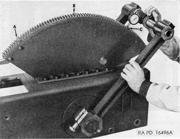
i. Install the gear sector with correct shim, as determined by use of the elevating gear sector alining radius bars (figs. 16, 17, and 18) (depot maintenance only). Install bars on casing, attach a dial indicator to the bars, and place a pin of 0.2880 inch
Figure 93. Checking radius of elevating gear sector.
143
diameter between the teeth of the sector; take readings from the surfaces of pin at three convenient points A, B, and C to determine whether the radius of the sector is the same throughout (fig. 93). If the readings do not agree within 0.002 inch, it will be necessary to use another shim of different thickness. Repeat the process until all readings are within 0.002 inch of each other. The sector must be fastened securely in place during the selection of the proper shim. Install all bolts and safety nuts (figs. 88 and 89) and drive in the taper pins. Tighten all nuts after pins have been installed. The purpose of the shims of varying thickness is to provide a means of obtaining a constant radius for the sector in relation to the trunnions.
j. To install the equilibrator rod bracket for the gun M2 (depot maintenance only), mount the shim and bracket in position and install the four bolts and safety nuts. Do not tighten the nuts until the taper pins have been installed. If a new shim is installed, use the bracket to lay out the location for the pin holes and drill holes oversize prior to the installation of the shim. If a new bracket is installed, ream the pin holes to correct to correct size after the bracket is mounted. Install the pins and tighten the safety nuts.
Caution: On the gun M2, the equilibrator rod openings in the gear sector and bracket must be in alinement to insure proper equilibrator action. If new or different shims are installed for the elevating gear sector, shims of corresponding thickness must be used for the bracket.
k. Install top, side, and rear covers.
l. Check fit of side cover; the covers will have a clearance of 0.002-inch from the breech casing at all points of the perimeter.
60. Adjustment of Rear Cover Assembly
a. GENERAL.
(1) The rear cover assembly must close firmly against the automatic loader assembly when the rear cover attaching bolt is installed.
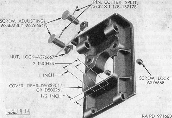
(2) The rear cover assembly on guns of recent manufacture has two adjusting screw assemblies (fig. 94) that contact the crosspiece cover on the automatic loader. On older gun assemblies, abutment surfaces on the rear cover contact the crosspiece cover. At the time of overhaul or rebuild, all covers not equipped with adjustable screw assemblies will be replaced with covers having adjustable screw assemblies.
144
Figure 94. Parts of newer type breech casing rear cover.
(3) If a new or different rear cover assembly, automatic loader, or crosspiece cover is installed, the screws may need adjusting.
b. ADJUSTMENT OF THE SCREWS.
(1) Remove the cartridge deflector bracket.
(2) Open the rear cover and remove the cotter pins from the nuts on both adjusting screws (fig. 94).
(3) Close the cover and remove both lock screws from the rear of the cover (fig. 94).
(4) Turn the adjusting screws in tight against the crosspiece cover of the automatic loader. Pressure must be equal on both screws and the head of each screw must make full contact. Prussian blue may be used to test the contacting surfaces.
(5) Install the locking screws and tighten to hold the adjustment (fig. 94).
(6) Open the cover, tighten the two lock nuts, and install the cotter pins (fig. 94).
(7) Close the cover and install the cartridge deflector bracket.
Note. If difficulty is encountered in the field in reassembling loaders to breech casings on guns with rear breech covers having the lower rib, modify the covers by cutting a groove 1/2 inch deep and 2 inches long centered in the lower rib of the cover (fig. 94).
145
61. Testing Elevation
a. Engage the elevating handcrank and operate through full range of elevation to determine if binding or backlash occur at any point.
b. If a new elevating gear sector or new or different gear sector shims were installed, it may be necessary to run in the sector and pinion with lapping compound to obtain smooth operation (par. 74 a (13) ) or to vary shims of trunnion bearings (par. 100k or 218f).
c. Refer to paragraph 75 for tests and corrections for binding, backlash, and vertical alinement of gun.